
Winding arrangement variations
Table 1.4 lists the winding variations for the bearingless machines described in this book – a brief description was also provided in the introduction chapter. In this chapter, further electromagnetic arrangements with integrated magnetic bearing and motor functions are described. A modification is put forward for the original radial magnetic bearing together with a split winding structure for the original motor. Also a p-pole and (p ± 2)-pole winding bearingless motor is described.
16.1 Modified radial magnetic bearings [1,2]
Figure 16.1 shows the cross section of a radial magnetic bearing. There are four windings consisting of two adjacent series-connected coils as shown. The winding current is the sum of the bias current and the feedback current (for radial positioning). Normally the bias current is dc. If the bias current has sinusoidal and co-sinusoidal variations in the x- and y-oriented windings then a revolving magnetic field is generated. The rotor can have conductors in order to act as an induction motor or it can be made of hysteresis or permanent magnet materials; with the interaction of rotor structure and the revolving magnetic field producing a rotational torque. The concept is quite simple and may be suitable for low-power motors, i.e., rather than being considered as a bearingless motor it can be considered as a magnetic bearing with limited torque-generating capability.
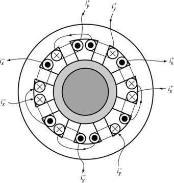
However, for high power motors, there are several problems that have to be addressed:
1. DC bias field optimization is required to reduce the braking torque in induction motors.
2. Elimination of induced parasitic rotor current.
3. The reduction of space harmonics.
4. Decoupling of the revolving magnetic field and radial forces.
If the rotor has saliency, as in a case of a switched reluctance machine, more torque can be generated; however, radial force generation is affected by rotor rotational position. If a permanent magnet rotor is inserted then it generates torque in the same way as a permanent magnet motor where there should be current on the rotor q-axis, so the radial force is again dependent on rotor rotational position. Hence in both cases the radial force regulation requires angular rotor position feedback (unlike magnetic bearings).
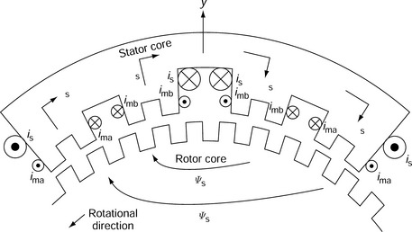
With a minor structural modification it is possible to obtain an improved bearingless motor design. Figure 16.2 shows the cross section of a y+ electromagnet with small teeth on the rotor and stator surface, similar to a stepping motor arrangement. Rotational torque is generated by magnetic saliency between the rotor and the stator teeth. Conductors carry the motor currents ima and imb; in the figure, if ima flows then the generated airgap flux produces an anticlockwise reluctance torque. The principle is similar to the hybrid stepping motor. The suspension conductors carry a current is. In this arrangement radial force generation is not influenced by rotor rotation because the rotor and stator teeth pitches are not equal. The suspension current generates a dc excitation flux Ψs, which also provides considerable torque. This bearingless motor is suitable for low-speed motor applications.
16.2 Modified motors [3–5]
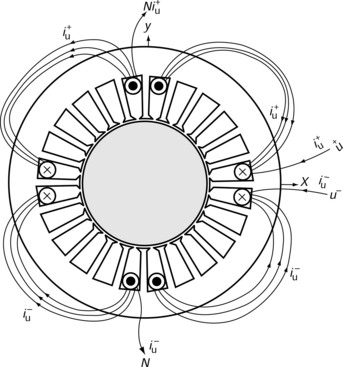
Figure 16.3 shows an example of a split motor winding structure. At the mid-point of the original motor windings the circuit is split and terminals u+, and u- are inserted so that the original neutral connections are separated. If the original windings are the u, v and w phases then u+, u-, v+, v-, w+ and w- windings are generated. This allows the currents i+u and i−u in windings u+ and u- to be independently regulated, and the difference in current values results in a radial force. For example, a y-axis radial force is generated by a u-phase current. The new neutral point N has six winding connections and the total number of inverter sections is six, requiring a more complex control strategy. The winding modification is easy to produce and it allows a 4-pole winding layout to also generate a 2-pole MMF wave so that there is no need for the insertion of an additional suspension winding. The rotor can be an induction, reluctance or permanent magnet type.
In a permanent magnet motor with a concentrated short-pitch winding, the phase coils are wound around the stator poles and the winding currents can be independently regulated to adjust the radial attractive force between the stator pole and rotor surface. With both this arrangement and with the split winding arrangement, to generate static radial force, the winding current has to be unbalanced. The number of phases can be more than three; to reduce the number of terminal connections a neutral point can also be connected internally.
These split winding configurations are suitable for low-power motors. The induced winding voltage increases as the speed increases and the instantaneous current is regulated by the difference between the induced voltage and inverter output voltage. Hence, for stable magnetic suspension, increased inverter voltage is required in order to regulate instantaneous current and obtain a fast response. The current drivers for the inverters provide both torque and radial force current components simultaneously.
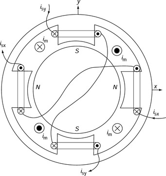
Figure 16.4 shows a single-phase motor with a 4-pole permanent magnet rotor. The motor has a single-phase winding carrying a current im. This sort of winding is popular in low power and low cost applications. The 2-phase suspension winding carries suspension currents isx and isy and these are responsible for the radial force generation in the directions x and y. In this situation the voltage and current requirements for the suspension winding are rather low due to the differential winding structure.
It is possible to modify a coreless motor to produce a bearingless drive [6–8]. Coreless motors are usually low-power motors without stator teeth or slots (in order to minimize cogging torque and torque-ripple) with the windings located in the airgap. The principle of force generation is based on Fleming’s law rather than the magnetic attractive force (Maxwell stress in the normal direction) and the force can be calculated from the force on the current-carrying conductors in the airgap. To achieve a reasonable force the conductor fill factor and current density need to be improved.
16.3 p-Pole and (p ± 2)-pole windings [9–11]
A p-pole and (P ± 2)-pole winding set consists, for example, of a 4-pole rotor and 4-pole motor winding with a 6-pole suspension winding, or a 6-pole rotor and 6-pole motor winding with a 4-pole suspension winding or even a 6-pole rotor and 6-pole motor winding with an 8-pole suspension winding. These winding sets, in theory, are capable of generating a radial force by the interaction of MMF and flux waves.
Figure 16.5 shows the cross section of a permanent magnet bearingless motor. Let us define the number of pole-pairs on the rotor as M and stator suspension winding pole-pairs as N. The figure shows the case when M = 2 and N = 3 and the rotational position is ωrmt and stationary angular coordinate is φs. The airgap flux density B is a sum of permanent magnet flux density Bpm and suspension current flux density Bs while the current in the main M-pole-pair motor winding is zero. Hence the airgap flux density can be written as
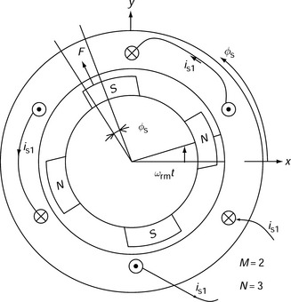
where θs is the phase angle of the suspension winding current. Note that the airgap flux density distribution is approximated by a sinusoidal function. In addition, the magnetic circuit is assumed to be linear.
Let us suppose that ΔF is the radial stress force in the airgap area for a small angle Δφs. The airgap area is given by
where R and l are airgap radius and axial length respectively. Then ΔF is:
so that the x-axis radial force is obtained from the integration of ΔF around the airgap; substituting (16.2) into the equation produces
Substituting flux density B, as given in (16.1), into the integration part of (16.4) yields
Note that M and N are greater than one so that integration of the first and the second terms results in zero. Only the third term is important, which can be rewritten as
When integrated, the first term becomes zero, but the second term may not be zero if M – N = ±1. When M − N = 1, executing the integration produces
so that the radial force is
In the similar way, the y-axis radial force can also be derived. These can be written in a matrix form
For the case of M − N = −1, the radial forces are
From these equations, the following can be observed:
1. The radial force amplitude is proportional to the product of the flux densities Bpm and Bs, the airgap radius and the axial length.
2. The direction of the radial force is regulated by the phase angle of the suspension current.
3. A condition where M − N = ±1 indicates that the difference in pole numbers in motor and suspension windings is two, i.e., p-pole and (p±2)-pole combination; for example, in a 4-pole motor the suspension winding should have six or two poles.
In practice high pole numbers can only be applied to low-speed motors and the flux amplitude should be less at high frequency to avoid excessive iron loss.
We can confirm radial force equation as derived in section 6.6. For a 4-pole motor and a 2-pole suspension winding, the suspension winding currents are
to satisfy (16.1). In addition, the angular frequency of the current should be twice the rotor rotational angular speed, where ω = 2ωrm. We then obtain the equation set
showing a correspondence between (16.9) and (16.13).
Suppose that the stator teeth flux density due to the permanent magnets and suspension current in a bearingless PM motor are 0.8T and 0.25T respectively. Let us also suppose that the tooth width is about half the tooth pitch. Find the radial force using (16.9).
In the airgap, the flux density due to the permanent magnet excitation is 0.8/2 = 0.4 T. When the suspension winding is excited the airgap flux density is either increased or decreased by 0.125 T, i.e., in the airgap Bpm = 0.4 T and Bs = 0.125T. Substituting these values into (16.9) produces
where D is a rotor diameter. If D and l are given in cm, then the force is F = 0.3 × D × lkgf. This corresponds to the primitive bearingless motor in section 8.3.
References
[1] K. Sakai and I. Morino, “Self-levitated Motor”, Japan patent H3-2540.
[2] Higuchi, T., “Magnetically Floating Actuator Having Angular Positioning Function”. United States Patent No. 4 683 391, 1985. [March 12].
[3] Meinke, P., Flachenecker, G., “Electromagnetic Drive Assembly for Rotary Bodies using a Magnetically Mounted Rotor”. United States Patent No. 3 988 658, 1974. [29 July].
[4] Santisteban, J.A., Salazar, A.O., Stephan, R.M., “Characteristics of a Bearingless Motor with Split Windings”. IPEC, Japan, 2000:367–370. [April].
[5] Amrhein, W., Silber, S., Nenninger, K., “Levitation Force in Bearingless Permanent Magnet Motor”. IEEE Trans. on Mag., Vol. 35, No. 5, 1999:4052–4055. [September].
[6] L. S. Stephens and H.-M. Chin, “Robust Stability of the Lorentz-type Self Bearing Servomotor”, ISMB-8, August 2002 at Mito, pp. 27–33.
[7] T. Tokumoto, D. Timms, H. Kanebako, K-I Matsuda and Y. Okada, “Development of Lorentz Force type Self-Bearing Motor”, ISMB-8 2002 August at Mito, pp. 59–64.
[8] Aoyagi, S., Chiba, A., Fukao, T., “An Analysis of Radial Forces in a Coreless Motor”. IEEJ paper in Technical Meeting on Linear Drives LD-01-98 at Kyoto, 2001:1–6. June 6,
[9] Okada, Y., Dejima, K., Ohishi, T., “Analysis and Comparison of PM Synchronous Motor Induction Motor Type Magnetic Bearings”. IEEE Trans. on IA, Vol. 31, No. 5, 1995:1047–1053. [September/October].
[10] Ohishi, T., Okada, Y., Miyamoto, S., “Levitation control of IPM Type Rotating Motor”. ISMB, Kanazawa, Japan, 1996:327–332.
[11] Bichsel, J., “The Bearingless Electrical Machine”. NASA Conf. Publ, USA, 1992:561–573.