
Chapter 7. Working with Relationships
In this chapter
Creating a Relationship with a Global Value
Creating Cross-Product Relationships
How and When to Use Multiple Files
FileMaker Extra: Managing the Relationships Graph
Relationships Graphs and ERDs
Chapter 5, “Relational Database Design,” outlined some database theory that helps produce an ERD—an entity-relationship diagram that shows the fundamental building blocks of a database system and the ways in which they relate. In Chapter 6, “Working with Multiple Tables,” we showed how to use FileMaker’s relationship tools to turn an ERD into a working FileMaker database. This might mislead you into thinking that the Relationships Graph is really the same thing as an ERD, and that the relationships you build there match one-to-one with the relationships you sketch out on your ERD.
In fact, there’s a lot more to relationships in FileMaker. The Relationships Graph certainly handles all the structural relationships present on an ERD. But there are many other ways to use relationships in FileMaker. The ERD-based relationships are the structural core of any FileMaker database (or any relational database), but this chapter takes you beyond the core and shows you some other ways you can use relationships in FileMaker. It also delves further into the features of the Relationships Graph, and discusses different ways of organizing files, tables, and table occurrences in a FileMaker system.
Bottom line: The Relationships Graph is actually a superset of your ERD. It certainly has the ERD wrapped up in it, but it might well contain other important structures and relationships as well. Those techniques are the subject of this chapter.
As did the previous chapter, this one also uses the Small Task Management database. You can download it from the author’s website as described in the Introduction. Although the name is the same as the database from Chapter 6, the downloadable database for this chapter incorporates the changes made here, so make certain that you look at the Chapter 7 version if you want to compare the downloadable database with the text of the chapter.
Relationships as Queries
Relationships can be more than classical database relationships in FileMaker Pro: They can be saved queries (something that does not exist in the world of SQL). In the Small Task Management database created in Chapter 6, you saw how to add a Tasks portal to the layout based on the Projects table as well as the layout based on the Assignments table.
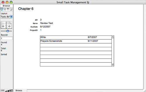
Figure 7.1 shows the Projects layout with the Tasks portal in it.
Figure 7.1. Use a portal to display tasks for a project.
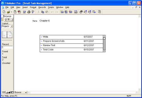
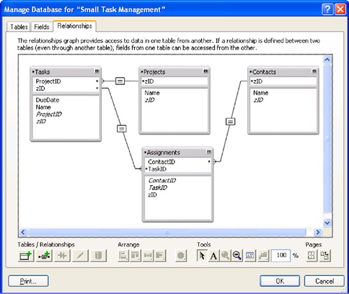
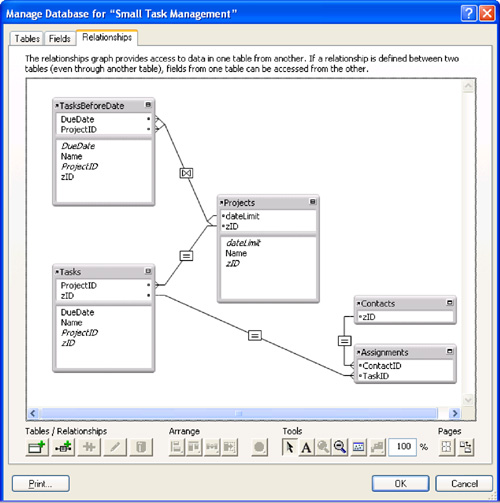
The portal looks into the table of tasks and is based on the fundamental one-to-many relationship between a project and task set, based on a shared key called zID in Projects and ProjectID in Tasks. But the portal also represents a kind of query, which says, “Show me all tasks for this project.” Figure 7.2 shows the relationships graph that includes this relationship as well as others for Contacts and Assignments.
Figure 7.2. A Relationships Graph shows tasks and projects.
When you start thinking about queries, the question immediately arises as to how complex the query can be. Relationships are often (but not always) simple matches of key values, but queries typically involve many components. With its relationship structure, FileMaker can do that. You can create a relationship that is a saved query that will, for example, display not only all the tasks for a project, but also those tasks for a project that have a due date before or after a given date.
The database as it is now contains the basic relationship of tasks for a project. To be able to create a new relationship to implement this query, we need to add a field to the database and then delve into three new concepts in FileMaker relationships: the concept of non-equijoins, the concept of a table occurrence, and the concept of a multiple match.
The new field to add is a date field that you can use in the relationship as a cut-off date before or after which data will be included (or excluded) from the Tasks table. Dates already exist in the Tasks table. The new field is a Date field that is added to Projects. It will contain the date that governs the complex relationship; in this example, it will be called dateLimit.
Non-Equijoins
Refer again to Figure 7.2, which illustrated the relationship between Tasks and Projects. Notice that the line representing the relationship has an equal sign right in the middle. To explore what that means, you can double-click the relationship line to edit the relationship. Figure 7.3 shows the Edit Relationship dialog.
Figure 7.3. FileMaker can use any of seven different operators to compare match fields.
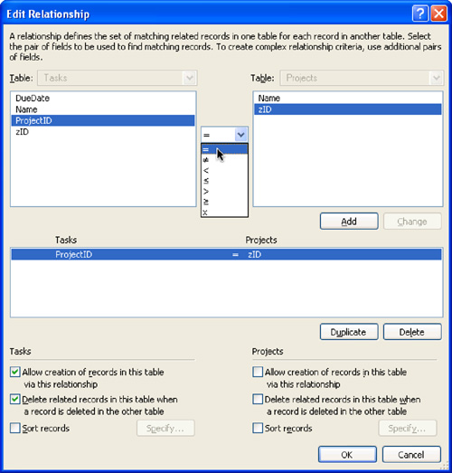
The middlemost box shows the match field or fields defined for this relationship. This current relationship is built between a ProjectID in Tasks and a zID in Projects. The match criterion is based on equality, meaning that records match (and hence are displayed in a portal that shows records from this relationship) if and only if the ProjectID in Tasks is exactly equal to the zID in Projects. This is the correct behavior for the structural relationship represented on the ERD. Such a relationship, based on equality, is called an equijoin.
The upper part of the Edit Relationship dialog is where the match actually is defined. You’ll notice, in Figure 7.3, that equality is not the only operator available for defining a match. In fact, you can build relationships based on combinations of any of the seven comparison operators.
To build the new relationship that implements the query showing you a project’s tasks that are due before or after dateLimit, you will need to build a nonequijoin relationship that uses ≥ or ≤ to match to the date field in Tasks. You could update the existing Relationships Graph to modify the relationship between Tasks and Projects, but it makes more sense to add a new relationship that implements this query while leaving the existing one intact because both relationships have useful but different purposes in the database.
Matching Multiple Values
As you saw in Chapter 2, “Using FileMaker Pro,” the Quick Start screen lets you filter the various starter solutions by typing in the field at the upper right. This is a useful feature, and it can be implemented in a number of ways—the following is one of them.
First, create a field (it is usually a global) in a table to contain what is typed into the filter field. This can be a field in the table itself, and you can use a self-relationship as described later in this chapter, but it could be a field in another table. What you now need to do is to create a relationship between the filter field and the field containing the words you want to filter. The problem is: what operator do you use?
One way to do this is to create a calculation field that contains each word separated by a carriage return. Because an equijoin matches based on any of the values in a field, this will do the trick. For example, if the value of the field containing the data is computer furniture, it will match computer furniture in an equijoin. However, if the data in the field is
computer
furniture
it will match either computer or furniture.
If the field containing the data is called thing, here is the calculation:
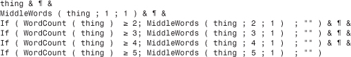
It creates a calculation each value of which has something to match: the whole name, the first word, and then, for each of the next words, a value for each word.
Adding a Table Occurrence to the Relationships Graph
We used the term table occurrence sporadically throughout Chapter 6 when referring to the graphical table representations in the Relationships Graph. Why not just call them tables and be done with it? Well, they’re not the same thing. An underlying table (or source table, meaning those tables that appear in the Tables tab of the Define Database dialog) can appear multiple times in the Relationships Graph. In fact, anytime you want to have more than one relationship between two source tables, you need to add an additional occurrence of at least one of the source tables to the Graph. You cannot create multiple relationships between two table occurrences in the Graph: There must always be one and only one path between two related tables in the Graph. If you want to relate table A to table B in two different ways, you need two occurrences of at least one of the tables.
In the current example, you want a new view of Tasks from the perspective of Projects based on a nonequijoin match of dates. Therefore, you need to add a new occurrence of the Tasks table to the Graph. So far, FileMaker has created all table occurrences for you automatically. Anytime you add a new table to a database, FileMaker adds a corresponding table occurrence to the Graph and gives it a name identical to that of the underlying table. Now you need to add a new occurrence of Tasks to the Graph by hand. To do this, open the Relationships Graph in the Define Database dialog and click the Add Table Occurrence icon in the lower-left corner (it is highlighted in Figure 7.2). Figure 7.4 shows the resulting Specify Table dialog.
Figure 7.4. You can add a new table occurrence to the Relationships Graph.
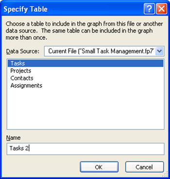
In the Specify Table dialog, choose a source table to include in the Graph. In this case, you want to add another occurrence of Tasks. Notice that FileMaker instructs you to “give this table a unique name in the graph.” At the bottom of the box is a place for you to name the table occurrence. Because the original occurrence of the Tasks table is already named Tasks, you need a new name. FileMaker automatically generates a name with a number added to the last occurrence name. We recommend a name that says something about the way the new relationship will be used. In this case, TasksBeforeDate fits the bill. Figure 7.5 shows the Relationships Graph with the new table occurrence, as well as the dateLimit field you added to Projects.
Figure 7.5. A second occurrence of the Tasks table has been added to the Graph.
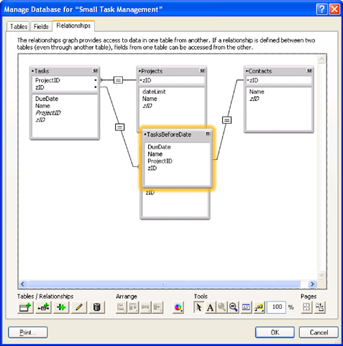
All that’s left is to create a relationship from Projects to this new table occurrence, which will incorporate the dateLimit field into the match criteria. To begin, you can do a bit of cleaning up of the Relationships Graph. Two simple ways of cleaning it up are to rearrange the table occurrences and to minimize the ones you are not working on. Figure 7.6 shows the Relationships Graph rearranged and ready for the new relationship to be added between Projects and TasksBeforeDate.
Figure 7.6. Rearrange and minimize table occurrences to make the Relationships Graph easier to work with.
Defining a Relationship with Multiple Match Criteria
Chapter 6 showed you how to define new relationships in the Relationships Graph with a graphical technique consisting of dragging from one match field to another. In addition, you can add a new relationship simply by clicking the small Add Relationship icon (the second icon in the Tables/Relationships icon group at the lower left of the Relationships Graph as shown in Figure 7.6). Clicking that icon brings you the familiar Edit Relationship dialog, but it’s initially completely empty.
Begin by selecting the two tables that are to participate in the relationship. Choose Projects on the left and TasksBeforeDate on the right. Then define the first match criterion. Select the ProjectID field from TasksBeforeDate and the zID field from Projects, make sure that the menu of operators in the middle shows an equal sign, and click the Add button. So far it looks exactly like the Edit Relationship screen for the original Projects-Tasks relationship, as shown in Figure 7.3, except that the table occurrence on the right is now TasksBeforeDate instead of Tasks.
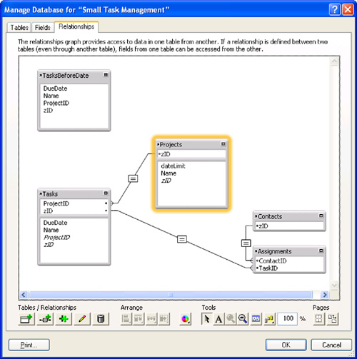
But you still need to tell FileMaker to consider only those Tasks on which the due date is before the cut-off date in the dateLimit field. To make this happen, you add another criterion to the relationship. Select dateLimit on the left in Projects, DueDate on the right in TasksBeforeDate, and from the operator menu in the middle, select the > sign. Click Add, and the new match criterion is added in the middlemost box, as shown in Figure 7.7.
Figure 7.7. Using a nonequality condition to build a relationship.
Notice what that middle box is saying now. There’s a large AND in the left margin, which says that this relationship pulls only those tasks for which the project ID matches and the due date is before the cut-off date.
Relationships in the Relationships Graph are bidirectional; you can access one table occurrence from the other side. This does not matter with equijoins. However, with nonequijoins, you must make certain that the logic recognizes which table is on which side. In this case, because the cut-off date is in Projects on the left, the operator to select due dates for Tasks (on the rate) must be >. If Tasks were on the left, the operator to select due dates would be ≤. Both relationships would enforce the same logic.
One of the fastest ways of implementing this type of relationship is to create the necessary table occurrence (you normally only need one new occurrence because the unique path will be created based on the new occurrence and the old occurrence), and then draw a link as you normally would do. This will, by default, be an equijoin, but you can change the operator if you need to. From this first link, you can double-click the operator symbol in the Relationships Graph and modify it, including adding new components to the relationship.
 You might be wondering how to create a multiple-match relationship that works if any of the criteria is true, as opposed to those that work only if all the criteria are true. This isn’t possible, unfortunately. To learn more, see “No
 OR Conditions with Multiple Match Criteria” in the “Troubleshooting” section at the end of this chapter.
Notice also how FileMaker represents this new relationship in the Relationships Graph. Each end of the relationship line forks to indicate the multiple match criteria—and the operator symbol in the middle of the line is a curious kind of X, indicating a complex match with multiple operators at work. Figure 7.8 shows the Graph with the new relationship.
Figure 7.8. The Graph indicates when a relationship is based on multiple match fields. The [X] comparison operator shows that multiple operators are in use as well.
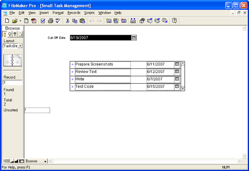
To use the new relationship, you could draw another portal on the Customer layout. Base it on TasksBeforeDate instead of plain Tasks, and use the same data fields from the source table. The result should be similar to what you see in Figure 7.9.
Figure 7.9. More complex relationships can produce sophisticated views, such as the TasksBeforeDate view shown here, which uses a portal onto the complex relationship as well as the FileMaker Pro drop-down calendar interface elements.
To add a comparable TasksAfterDate relationship, you can repeat the steps in this section; just reverse the direction of the relationship operator (in other words, the cut-off date will be before the task due dates).
These three concepts—nonequijoins, multiple table occurrences, and multiple match criteria—afford you extraordinary flexibility as a database developer. The sections ahead explore examples that show how to use these tools to solve particular problems of database design.
The date limit field in Projects can be a global value in some circumstances. If you are designing an interface in which only one window can be open onto the portal, you can set a value to control the portal using a global. However, if you are going to allow multiple windows to be open, the portals displayed in each of the windows should be sensitive to a nonglobal value that can usually be set in that window. Allowing multiple windows with the TasksBeforeDate portal shown in them means that if you use a global field, all of those portals will be set to the same set of data, which is probably not what you want.
Creating Self-Relationships
In the previous section, you created a relationship controlled by a date in the Projects table to display related data from Tasks. Nothing prevents you from using the same logic to relate one occurrence of the Tasks table to another occurrence of the Tasks table. The controlling date field could be in the Tasks table itself. Relating a table to itself is a useful feature of relational databases.
The basic process would be the same: You select a field in the controlling table (which would be a Tasks occurrence, such as the original Tasks table), and you implement the relationship to a new occurrence, which would drive a portal that is displayed in the window of the basic Tasks occurrence. In practice, you do not even have to add another date field. You can use this mechanism to display the tasks due before the date of a given task in the same project. This section shows you how to do that.
Figure 7.10 show the Relationships Graph with a new occurrence of Tasks created. It has been named TasksBeforeThisTask using exactly the same process described in the previous section.
Figure 7.10. Add yet another Tasks table occurrence to the Graph.
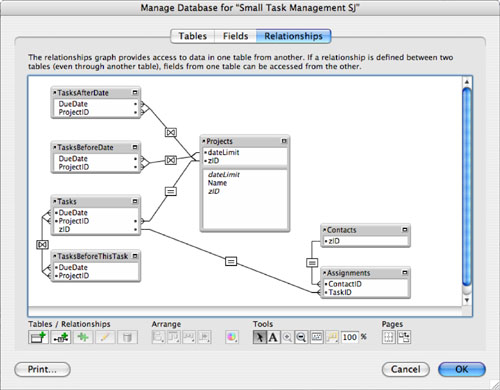
Instead of creating a relationship to Projects, you can create a relationship between the new occurrence, TasksBeforeThisTask, and the original Tasks occurrence. Figure 7.11 shows that relationship.
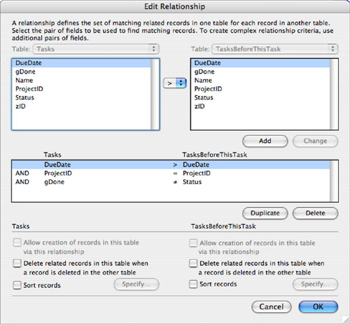
Figure 7.11. Create a self-join relationship.
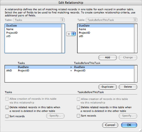
Both occurrences are based on the Tasks table, so the fields are the same. Match the DueDate field of Tasks to DueDate in the new occurrence so that DueDate in Tasks is greater than Due Date in the new occurrence (or vice versa—it doesn’t matter as long as you are consistent in your naming). You also need to match the ProjectID in both Tasks records so that you are including only peer tasks with the same Project ID. This is the same logic you applied in the previous section, and you can now build a new Tasks layout that displays data for a Tasks record at the top and display a TasksBeforeThisTask portal below as shown in Figure 7.12. As you page through tasks, you will see that the portal is always updated to show peer tasks on the project with due dates before the current task’s due date.
Figure 7.12. Display the self-join.
Creating a Relationship with a Global Value
You can create a relationship to a global value. As noted previously, this is one way to implement the Project-Tasks relationship where a date controls the selected Tasks records, although you must consider the issue of multiple windows. You can also use a constant global value, one that is not entered dynamically by the user, in order to implement a relationship.
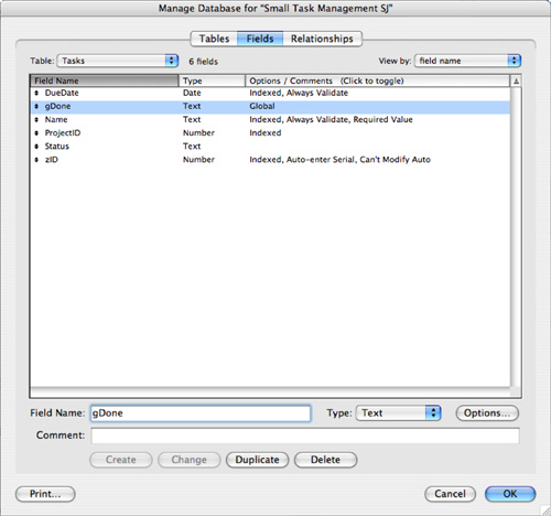
An obvious candidate for such a relationship is a modification to the preceding self-join. You can add a third component to the join so that you select peer projects (that is, those with same Project ID), due dates before the given task’s due date, and a new field—status—equal to a constant value such as “done”. To implement this, you would add two fields to the Tasks table as shown in Figure 7.13. The fields are Status and gDone. One is the status of the task, and the other is a global value that contains “done.”
Figure 7.13. Add fields to the Tasks table.
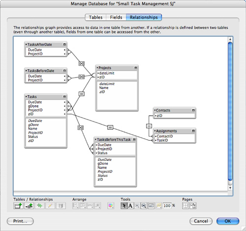
When you add these fields to the Tasks table, you will notice that the Relationships Graph is automatically updated. As you can see in Figure 7.14, all the occurrences of the Tasks table now have the new fields visible in them.
Figure 7.14. FileMaker Pro updates the fields lists in the table occurrences.
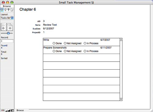
If you create a Status value list, you can add a set of radio buttons to the portal records as shown in Figure 7.15.
Figure 7.15. Add Status radio buttons to the portal.
Temporarily add a gDone field to a Tasks layout (it doesn’t matter which one). Type Done in the field to set the global and then delete the field. Now you are ready to modify the relationship.
It will make your testing easier if you add the Status radio buttons to the Tasks layout as well. If you copy it from the portal, make certain that in the portal the field used is from TasksBeforeThisTask, and in the Tasks layout it is the same field from Tasks. To get things going, you might want to go to the Tasks layout, show all records, and then click In Progress for the current record. Use Replace Field Contents from the Records menu to set all records to In Progress. Then you can click Done periodically to see how the portal changes. You can repeat this process to reset everything to In Progress.
Figure 7.16 shows the last step. Add a component to the self-join so that you are selecting tasks for the same project, due before the current tasks’ due date, and with a status that is not equal to the value of gDone (which is “Done”).
Figure 7.16. Add a component to the self-join.
This relationship works, but it is somewhat fragile. If you use less than or equal instead of greater than in implementing your relationship for due dates, the date of the given task shows up in the TasksBeforeThisTask portal. Because equality is allowed, the given task might show up in TasksBeforeThisTask. To remove this fragility, add yet another component where Tasks::zID is not equal to TasksBeforeThisTask::zID. This prevents a task from showing up in both places.
This relationship, whether implemented between two tables or as a self-join, demonstrates the basics of a vast number of queries that you can implement in FileMaker Pro as relationships. One of the virtues of implementing queries as relationships is that they are always there: The logic is supplied in the relationship, and you do not have to worry about implementing find requests. Everything that you can implement in the database—be it in the Relationships Graph, in validation rules, or with auto-entry of data—represents something that does not have to be implemented in the scripts and interface or with user commands. That means after it is done, it is there and correct for all uses.
Self-joins come into play whenever you want to relate like objects. For example, you can use them to implement hierarchies such as employment structures where each employee has a manager, who in turn has a manager.
Creating Cross-Product Relationships
In working with nonequijoin relationship matches, you might have noticed one oddball operator in the little menu of match criteria. Most of them are familiar comparison operators—but what about the last one, the one that looks like an [X]?
That operator is known as a cross product (or Cartesian product, if you really want to show off). The cross product does one and only one thing: It provides a “universal match” between the records in two tables. What this means is that it does no limiting of any kind. If you think of a relationship again as a kind of query, a cross-product relationship is a “find all” query. If you define a cross-product relationship from Projects to Tasks, a portal based on that relationship would always show all Tasks, no matter which Project record was being viewed. The choice of fields on the left and right sides is more or less unimportant; this “all to all” relationship is fulfilled regardless of the choice of match fields.
Cross products really make sense only by themselves, in single-match relationships. They have no effect at all if they’re added into multimatch criteria sets. A cross-product match condition is always true, so it can never further limit the potential matches of other criteria. Of course, if that makes your head spin, you can just take our word for it.
Savvy users of older versions of FileMaker might recognize that the cross-product operator replaces the technique that used to be known as a “constant” or “always-true” relationship. In that technique, you had to define specific fields on either side that explicitly matched each other (generally a pair of calculations that each evaluated to 1) and build a relationship between the two fields. Beginning with FileMaker 7, cross products provide the same feature in a more integrated fashion.
Well, that explains what a cross-product relationship is, but not how you might want to use one. The cross product is the ultimate nonstructural relationship. After all, its purpose is to show all of something. These are generally used for various user-interface purposes. Sometimes you might want users to pick from a list of things, for example, and it’s more pleasing to allow them to pick from a scrolling list in a portal than from a drop-down list or menu. Generally such techniques need to be coupled with some scripting to react to users’ choices.
![]() For further examples of the uses of cross-product relationships, see Chapter 17, “Advanced Portal Techniques,” p. 495.
For further examples of the uses of cross-product relationships, see Chapter 17, “Advanced Portal Techniques,” p. 495.
Working with Multiple Files
In all the discussions of multitable systems in Chapters 5 and 6 and so far in this chapter, we’ve assumed that all the tables you want to work with live within a single FileMaker file. The capability to have many tables in a single physical file is, after all, one of the more convenient features of FileMaker. But there are still many reasons to build systems that are multifile, in addition to being multitable. This section reviews the mechanics of working with several files at once, and then discusses different design strategies that use a multifile structure.
So far we’ve looked just at relationships between tables within the same file. But it’s also possible to build relationships between tables in different files. A very common situation arises when you are building a solution that uses data from an existing FileMaker database. In the case of the example used in this chapter, perhaps the Contacts table already exists in its own database file.
To reference the Contacts table in another file from your file, you only need create an external data source that uses the other file. You can then use that external data source to create new table occurrences for those tables. The data remains in the external file, but you can access it through the file references.
In FileMaker Pro 7 and FileMaker Pro 8, this functionality was referred to as file references. Now external data sources include both file references and ODBC references.
![]() The use of external data sources lets you use other FileMaker database files. You can also reference external databases using SQL and ODBC as described in Chapter 21, “Connecting to External SQL Data Sources,” p. 603.
The use of external data sources lets you use other FileMaker database files. You can also reference external databases using SQL and ODBC as described in Chapter 21, “Connecting to External SQL Data Sources,” p. 603.
Creating an External Data Source
External data sources are an extremely important topic in FileMaker. In a number of places in FileMaker, you might want to refer to or work with another file. Here are some of the things you can do with other files in FileMaker:
- Call a script in the other file
- Use a value list defined in the other file
- Refer to one or more tables from the other file in your Relationships Graph
To do any of these things, you must first create a reference to the other file using an external data source. A file reference simply tells FileMaker where and how to find another file. FileMaker is capable of working with external files present on a local hard drive, present on a shared network volume, or present on an available FileMaker Server. You can also specify multiple search locations for a file, and the priority in which they should be searched. You can, for instance, create a file reference that says, “First search for the file on the FileMaker server at 192.168.100.2. If you don’t find it there, look on the FileMaker server at 10.11.1.5. If you don’t find it there, give up.”
Before FileMaker 7, versions kept track of these references behind the scenes and didn’t let you alter the order in which FileMaker searched for a given file. Problems with file references were harder to spot in previous versions and could occasionally give rise to a problem called crosstalk, in which the wrong copies of files could be accessed by mistake.
![]() For more on the concept of crosstalk and its relationship to file references, see “Crosstalk,” p. 564.
For more on the concept of crosstalk and its relationship to file references, see “Crosstalk,” p. 564.
Since FileMaker 7, each physical file maintains its own list of file references. You can work with these references centrally and create them on the fly as needed. Let’s see how this works in practice.
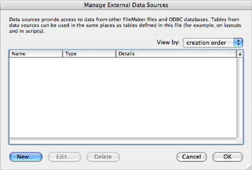
Your first step is to define an external data source that will contain a file reference to the external file. To do this, choose File, Manage, External Data Sources. Click the New button on the next screen, and you’ll see the Manage External Data Sources dialog, shown in Figure 7.17.
Figure 7.17. Add external data sources to a FileMaker database file.
When you click New, or select an existing data source and click Edit, the dialog shown in Figure 7.18 opens. You can name the data source and select whether it is an external FileMaker file or one accessed via ODBC. Those files are discussed in Chapter 21.
Figure 7.18. Edit the external data sources.
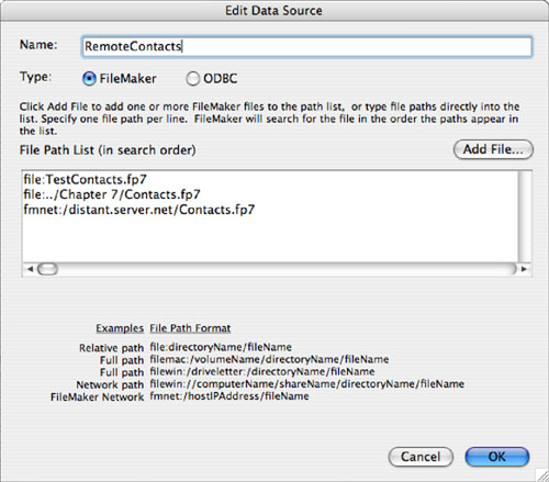
Then you provide the actual file references for the data source. You can type in the path to the file that you want to use, or you can click Add File to use the standard Open File dialog to select the file from your local hard disk or the network. As you can see in Figure 7.18, you can provide several file references. FileMaker will search them in order until it finds a file to use.
In general, all the different file paths in the path list point to the same file; that is, a file with the same name and contents. In theory, you could also use a single path list to point to a number of different files, indicating that the later ones should be used if the earlier ones can’t be found. You could perhaps use this feature to fall back to other versions of a file or system if necessary.
In Figure 7.18, you can see a reference to a file in the same folder as the database into which the file reference is created. Below that is a file reference to a file in a folder with a common parent folder as that of the database file. On the third line is a reference to a file accessed through FileMaker Server or FileMaker peer-to-peer networking. In that case, as is always true when you use the Open Remote command, you connect to a copy of FileMaker and through it to the database. The other syntax connects to the database using your own copy of FileMaker.
As you can see at the bottom of the dialog, there are different forms of the syntax for Mac OS X and Windows. Because the file references are searched in order, you can vary them for your development process.
If you inserted a local reference to the file to aid offline development, you need to remember to remove that reference later, or perhaps move it lower on the list. Otherwise, FileMaker continues to search your local drive first, which is probably not desirable.
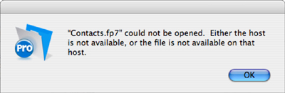
If none of the file references can be resolved, you will get an error message. Figure 7.19 shows the warning you see when a file reference can’t be resolved.
Figure 7.19. If FileMaker cannot find a referenced file after searching the specified search path, it displays an error dialog.
File references are resolved as FileMaker needs to access the given file rather than when the database opens. That improves the efficiency of cases in which not all file references are used in a particular session of FileMaker. It also is the reason why resolving file references occasionally can provide some frustration. If you have a situation in which sometimes there is an error in your FileMaker solution but not always, it might be that a file reference is to blame and the apparently randomness of the error is caused by the sequence in which file references need to be resolved. These intermittently appearing bugs can sometimes be tracked down by reviewing all the file references in your external data sources and verifying that they are correct. Trailing spaces at the end of the file references are a notorious source of error.
Adding an External Table to the Relationships Graph
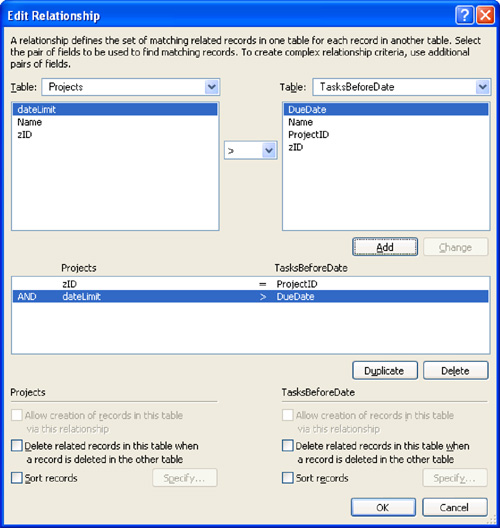
After you create the file references in your external data sources list, you can add tables from these external files to your Relationships Graph. If you open the Relationships Graph and click the Add Table Occurrence icon, you’ll notice something we didn’t highlight before. In the resulting Specify Table dialog is a menu that lets you choose which file you want to browse for table choices. This menu always includes the current file and any file references you defined using the techniques covered in the previous sections of this chapter. Figure 7.20 illustrates this point.
Figure 7.20. When adding a table occurrence to the Relationships Graph, you can base the new occurrence on a table in an external data source.
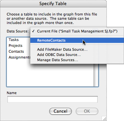
Because you name the external data source, you will see that name in the pop-up menu in Figure 7.20. Not only might you be accessing files in various locations, they may have different names, but the external data source name that appears in this dialog is what you work with.
The table is added to the Relationships Graph, much as all the other tables we’ve seen. The result is shown in Figure 7.21. There’s one subtle visual indication that the Customer table occurrence is based on a table from another file: The table occurrence name for Contacts 2 is italicized. In addition, if you hover the mouse over the arrow in the upper left of the table, you can see the data source name. Otherwise, it’s just as though you were working with a table in the same file.
Figure 7.21. In this Relationships Graph, the italicized title of the Customer table occurrence shows that the source table exists in an external file.
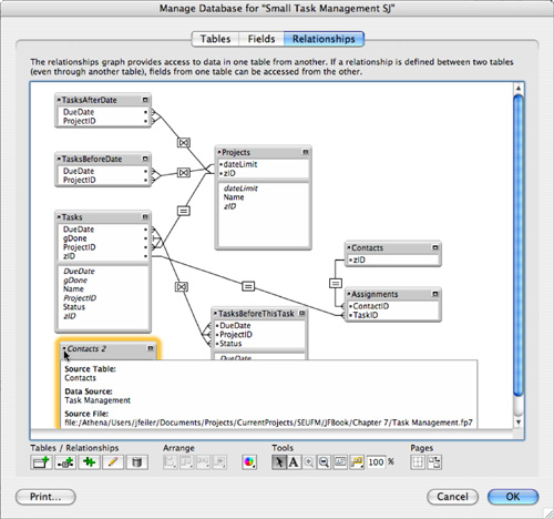
External data sources—such as tables, table occurrences, fields, layouts, and scripts—can benefit from a consistent naming scheme. Here, as elsewhere, the naming scheme you choose is less important than the consistency with which you apply it. In the Relationships Graph, the only clue that a table occurrence is external is the fact that the name is italicized. If it is important to emphasize that a data source is external, you might want to indicate that in the data source name.
How and When to Use Multiple Files
The preceding section showed the mechanics of creating a FileMaker system that uses tables from different files. It didn’t say much about the reasons why, in general, you might want to do such a thing. We offered the example of needing to work with a preexisting file owned by someone else. This is certainly a relevant case, but there are also reasons why you might choose to build your own systems with multiple files from the start. This section looks over some of the major reasons for using multiple files in a single database solution.
Working with Converted Files
FileMaker 7, 8, and 9 represent a very new way of building FileMaker databases. The differences between these and previous versions are significant enough that converting a system from a version older than 7 is not quite the easy, nearly transparent process that conversions between different versions of the product have been in the past.
![]() For greater detail on the conversion process, see Chapter 20, “Converting Systems from Previous Versions of FileMaker Pro,” p. 581.
For greater detail on the conversion process, see Chapter 20, “Converting Systems from Previous Versions of FileMaker Pro,” p. 581.
In versions of FileMaker prior to version 7, a single physical disk file represented each database table. A 10-table system used 10 different FileMaker files. Now, if you build that 10-table system from scratch, you could choose to put all 10 tables into a single physical file. But if you’re converting that system from, say, FileMaker 6 to FileMaker 9, you won’t have that option. The conversion process cannot roll separate files together into a single new FileMaker 9 file. Your 10-file (that is, 10-table) FileMaker 6 system becomes a 10-file FileMaker 9 system as well. The conversion process brings forward all the appropriate file references into each of the new FileMaker 9 files and populates the Relationships Graphs of each file appropriately, but structurally you’ll still have a set of 10 interlocking files, just as you did before. From that point, of course, you might be able to start rolling the tables together, but the process is largely a manual one.
Any system converted from previous versions of FileMaker is sure to have a large number of external file references. Many of these might be to the same file, but in different forms (with different directory paths, for example). The new system will probably work perfectly well like this. If it’s working, you’re likely to leave it alone. At most you might consider adding any new tables into existing files, when and if new tables become necessary.
The presence of multiple redundant file paths in a single file reference is characteristic of files converted from FileMaker 6 and earlier to FileMaker 9. In previous versions, if you worked with a file in multiple places over time, many or all of those places might end up in the file path list. Because FileMaker needs to search the entire file reference, item by item, all the unused file paths can cause significant slowdown in opening files.
![]() For more information on this problem, and on approaches to solving it, see “Fix File References,” p. 587.
For more information on this problem, and on approaches to solving it, see “Fix File References,” p. 587.
Separation of a System into Modules
FileMaker 9 makes it possible, even tempting, to put all the tables for a database system into a single file and be done with it. But is that always the best choice? Not necessarily. There are still several reasons to suggest that breaking things into multiple files might sometimes be a more suitable choice. The sections that follow examine a number of potential benefits to using multiple tables. We’re not presuming anything about how, exactly, you might choose to split up your tables. There are a few possibilities. If your system falls cleanly into several different modules, for example (let’s say Accounting, Orders, and Inventory), it might make sense to take the tables contained in each module and group each set in its own file. You might also want to split your system into a file of data tables and another file dedicated to interface layouts and application logic such as scripts; this possibility is discussed later in this chapter in “Separation of Data and Application Logic.”
Ease of Shared Development
FileMaker has always been a great rapid application development tool, but the product has tended to retain an emphasis on the single developer. It’s often been challenging for multiple people to work on the same FileMaker system simultaneously without getting in each other’s way.
In FileMaker 9, anyone with sufficient privileges can open ScriptMaker. If others have ScriptMaker open as well, you’ll be inhibited from editing only any scripts they have open, and any subscripts called by those scripts. But, in other ways, FileMaker 9 exacerbates the earlier problem in that scripts in FileMaker 9 can span multiple tables within a single file, aggregating together scripts that would be separated into different files in a multifile system. The more tables you group into a single file, the more likely that multiple developers will interfere with each other when editing scripts.
Things are a bit tougher with the database definition tools. Multiple developers can open the Manage Database dialog at once. But only one at a time can be in control of the database definition. The others can view any aspect of the structure, but cannot change it.
So, if you expect you’ll often have more than one person making script or database definition changes inside your system, it might make sense to try to separate your tables into groups and put each group in its own file to minimize the chances of developers getting in each other’s way.
Ease of Maintenance
Every database system needs maintenance. Files become fragmented, which makes access to them slower. Lost space needs to be reclaimed; indexes need to be optimized. FileMaker is no different. It’s a good idea to perform periodic file maintenance on your FileMaker files.
![]() For a discussion of file maintenance, see “File Maintenance and Recovery,” p. 570.
For a discussion of file maintenance, see “File Maintenance and Recovery,” p. 570.
One thing to consider is that the larger your file, the longer it takes to perform this periodic maintenance. The same is true for other maintenance tasks, such as backing up. If your system is particularly large, say in the hundreds of megabytes or into the gigabyte range, your backups will take a long time to run. This might not be a problem if you run your backups at night, but in many mission-critical systems, data is backed up periodically during the day—sometimes as often as hourly. If all your tables are in a single file, your choices are to back up all or nothing. There’s no way to back up only a few tables from a single file. Suppose that the system had one massive table of relatively static data, which changes on the order of only once a week, as well as many smaller tables of critical, highly changeable data. In the best of all worlds, you’d back up the huge table daily or weekly, the smaller ones perhaps as often as hourly. If all the tables are in one file, you’re out of luck. Each backup has to copy the single massive table again, even though it’s unlikely to have changed.
In the worst case, consider the problem of file recovery. In rare circumstances, a FileMaker file can become damaged or unusable due to a crash. If all your tables and data are in that one file, the consequences of a crash are potentially catastrophic. One bad event can in theory compromise your entire system.
Even if the worst doesn’t happen, you might still have to run a recovery on such a file. As with maintenance and backups, the time it takes to recover the file is in proportion to its size. And you need to recover everything—all the tables—even if the massive ones were undamaged and only the little ones were damaged in some way. Had the tables been separated into additional files, the consequences of a crash could have been mitigated.
None of this is to suggest that you should go back to the one-file-per-table model of previous versions, necessarily. It does mean that you should think carefully about how your database is going to be used, and whether there will be wide variation in size or usage pattern among tables. If such differences exist and can be predicted, it might be worthwhile to isolate certain tables in their own file or files.
Separation of Data and Application Logic
In FileMaker 9, as in previous versions, data and application logic are mixed together in a single file. A physical file contains not only a system’s data (the “database” portion of things), but also all the scripts, layouts, value lists, and the like that make up the “user application” portion of things. After a system has rolled out and is in use, if you want to continue to make changes to it, you have a limited range of choices.
One possibility is to work directly on the running copy. FileMaker permits this; you can edit scripts, add layouts, even add entire tables to a running system. Still, just because you can doesn’t mean you should. What if you make a mistake? (Mistakes do happen from time to time—in fact, we devote an entire chapter to avoiding and repairing them.) That mistake will affect users who are probably trying to get work done. It might be merely annoying, or it might be catastrophic. If the changes are small and you know what you’re doing, you might be fine making the changes online, so to speak. For more extensive changes, it’s not a great idea.
Another possibility is to work on a copy of the system. Make all your changes, test them every which way, and, when they’re all ready, integrate them into the current live system. But here’s where the data-and-logic problem rears its head. You can’t just replace the existing production files with your development copy—the production files almost certainly contain a different data set. And there’s no convenient way to merge your structural changes with the data in the live copy. To do this, you’ll have to shut down the live file and import its data into your development copy, and then bring the development copy online as the new production copy. Depending on the size of the data, this is often a long process, and there are several small potential pitfalls along the way, such as accidental generation of overlapping serial numbers or forgetting to reset global fields to default values.
Things are not really better on this front with FileMaker 9. Because a file can contain multiple tables, performing an update on a file might mean importing data into a great many tables, even if only a small area of the system has really changed. Separating the tables into several modules, as discussed previously, can help, but the problem remains.
Ideally, we’d be able to take a given data set and just swap a new interface in on top of it without all this talk of mass imports. Using a multifile architecture, this is a reasonable possibility if you separate your data and your interface into two or more separate files.
In fact, you might choose a structure in which the interface file contains no tables at all, simply external data sources. By the same token, the file with actual tables in it might contain no interface elements such as layouts.
If you separate interface from data, it’s reasonably clear that layouts belong in the interface file and tables belong in the data file. But where do scripts go? One solution is to place interface related scripts (such as those that interact with the user) in the interface file and noninteractive scripts in the data file. You might wind up with an interface script that calls a data-file script, but you will have factored the solution.
This is all true and good so far. In all fairness, though, we have to point out that there are some limitations to this technique:
- Security— Accounts and privileges are maintained separately in each file. It’s not possible to instruct one FileMaker file to draw its accounts and privileges from another FileMaker file. It’s possible to use external authentication methods to offload a lot of the work to an external authentication server, but it’s still necessary to create group-to-privilege mapping information in each separate FileMaker file. (For more information on security matters, see Chapter 12, “Implementing Security.”) So, in this example, you would have to create and maintain privileges in parallel in both the interface and the data files.
- Multiple Relationships Graphs— Even in this kind of scenario, the data file is going to need to be aware of most or all the structural relationships between data tables. If, for example, you want to create a calculation field that tells you how many items a given patron currently has checked out, that calculation field, which lives in a data table, needs to use a relationship between Patron and Checkout to compute that number. So, it isn’t possible to build a Relationships Graph in just the “interface” file—substantial portions of it might have to be replicated in the “data” file as well. The relationships graphs should be consistent but do not have to be identical. An interface Relationships Graph is likely to be more complex than one in a data file, particularly if it is used to create relationships that are like stored queries.
- “Stickiness” of the data tables— In theory, changes to scripts or layouts can be accomplished just by swapping out the interface file. But in our experience, many if not most significant updates end up touching the data side as well, even if only to add certain new calculations. The separation methodology described here still doesn’t give you a means to avoid making these additions to the data file. However, data file changes are quite a bit easier to write down and replicate than wide-ranging script and layout changes. Manual work might still be necessary in many updates, but it is still much less onerous than doing a massive import of one or more tables.
When you have separate interface and data files, be aware that deleting fields in the database file can cause interface elements to break, as can changes in field names. Adding fields to the database file cannot break the interface. That is why, in some cases, if a change is needed, it is implemented by creating a new field that scripts in the interface file can use. You can use the comment feature to mark both new and old field, and when your testing is complete, you can delete the old field. In some cases, both fields will co-exist for some time, even though it is not an elegant database solution.
Working Toward Reuse
As a final reason to consider a multifile structure, consider the idea of reuse. This is in some ways an extension of the earlier discussion of the idea of separating a system into modules. Suppose you want to use a module in several or many different FileMaker systems. You might want to consider isolating the functionality of the module in a single file and including that file in solutions that need the functionality.
As an example, suppose that you have a custom-built user management system that keeps track of users, passwords, and privileges. FileMaker 9’s new account management features are great, but you still might want to roll your own sometimes.
This is especially true in multifile situations. FileMaker’s access privilege system is still slightly hampered because each separate file stores its own account and privilege information, as we discussed previously.
You could create a User file that would include a table for user information, as well as tables for user groups—or even subgroups, if applicable. If records of user activity, such as logon and logoff times, were required, that information could be stored here as well.
To promote a module’s reusability, you could take advantage of some FileMaker features that promote abstraction, such as custom functions, script parameters, and script results. Suppose that you want to create a somewhat generic logging facility (that is, the capability to log user actions to a database table). You could create a Log table with fields for user ID, timestamp, and a textual description of the event. You could then create a logging script that takes a script parameter containing the text to be written to the log, and writes out a log record with this text, the current user ID (presumably stored in a global), and the current timestamp. With planning and forethought, it’s possible to create a module in FileMaker 9 with a high degree of reusability.
Let’s think about how you might use such a module. First suppose that you’re pursuing a strategy of data/interface separation such as the one described earlier in this chapter. Your main system consists of two files: MainData (that contains all the data tables, but no scripts or interface) and MainViewer (the interface file that contains scripts, layouts, and interface logic). You also have your user module, which is split into two files: UserData and UserAdmin.
You need to create a file reference from MainViewer to UserAdmin. You probably should not need to create a file reference from MainView to UserData. All the main system’s interactions with the UserData file should ideally be calls to scripts in UserAdmin; adding log records or checking a user’s privileges should not be done by checking the UserData tables directly, but by asking UserAdmin to do this and report on the success or failure of the request.
You would especially want to avoid any logic that would force you to create a table reference from UserAdmin to MainViewer or MainData. UserAdmin shouldn’t care about the nature or internals of any files or system that wants to use its services.
Not every group of related tables is likely to be suitable for this kind of modularization. But you might want to consider splitting out any subsystems that provide somewhat nonspecific functions, such as logging or user management, and making them into their own, semiconnected modules. Careful planning and exploitation of new features such as script parameters can help you create modules that can be smoothly integrated with various FileMaker systems.
Troubleshooting
Trouble Creating Related Records with Non-Equijoins
I want to create a relationship that allows creation of related records on one side of the relationship, but the box that enables that capability is grayed out.
You might have noticed that the option Allow Creation of Records in This Table via This Relationship has mysteriously been disabled when a nonequijoin is part of the relationship. This suggests that you have one or more nonequality conditions in your relationship match criteria. The rule is this: FileMaker can allow creation of related records only if the relationship in question consists only of conditions involving an equality comparison. This limits such relationships to using only the equal (=), less than or equal (≤), or greater than or equal (≥) operators.
Multiple match criteria are fine, as long as they’re all based on one of those three operators. This can actually be rather useful: A multimatch relationship that allows creation of related records automatically fills in all the key fields of the related record. But as soon as any nonequality condition becomes involved in the match, the capability to create related records goes away.
This makes sense if you think about it. FileMaker can create a record via an equijoin because there’s only one condition that satisfies the match criteria for the current record. Suppose that you’re on a Customer Layout, looking at customer number 17, and you have a portal into Invoices, in which the relationship to Invoices is an equijoin on CustomerID. FileMaker can create a new record in the portal by creating a new invoice record and setting the CustomerID to 17. But suppose that the relationship instead were based on a “not equal to” relationship? To create a record on the other side, FileMaker would need to create an Invoice record with a customer ID other than 17. Fine, but what customer ID should it use? There’s really no way to say. Similar reasoning holds for other nonequijoin types: There’s no sensible way for FileMaker to decide what match data should go into the related record.
If the capability to create related records is enabled, the key fields in the related record will always be populated with values equal to the key field in the parent record, regardless of which of the three allowable relational operators is chosen.
No OR Conditions with Multiple Match Criteria
Whenever I add multiple match criteria to a relationship, FileMaker always tells me the match will work if condition 1 AND condition 2 AND condition 3 are true. But I have a match that needs to work if 1 OR 2 OR 3 is true. Where do I set that up?
You don’t, unfortunately. Using the native FileMaker relationship features, relational matches are always AND matches whenever multiple match criteria are specified. If you want to mimic the effect of an OR search in another table, you need to find another means of doing that. Say, for example, that you have a database with tables for teachers, classes, enrollments, and students. From the viewpoint of a teacher, you want to be able to view all students who are outside the norm—they have either a very low GPA or a very high GPA. You could try to do this with two match criteria, but that would necessarily be an AND match, which would never be fulfilled (no student would have both a low and a high GPA at once). The solution here would be to create a stored calculation in the student table called something like ExceptionalGPA, defined as
If ( GPA < 2 or GPA > 3.75; 1; 0)
The calculation will have the value 1 when the student’s GPA is exceptionally high or low, and a value of 0 otherwise.
You could now create a field in the teacher table called Constant, and define it as a calculation that evaluates to 1. Then specify a relationship between the teacher table and the student table, with multiple match criteria: TeacherID=TeacherID, and Constant=ExceptionalGPA, meaning, “Find me all students with the same teacher ID and an exceptional GPA.”
FileMaker Extra: Managing the Relationships Graph
The Relationships Graph in FileMaker is a nice answer to developers who clamored for years for a visual representation of relationships in FileMaker systems. But for large or complex systems, with many table occurrences, the Graph has the potential to be a bit unwieldy. Table occurrences in the Graph take up a fair amount of space, and it can be difficult to organize the occurrences without creating a web of overlapping relationship lines.
You can use a number of tools for Graph management. For one thing, the small “windowshade” icon at the upper right of a table occurrence can be used to hide the fields in the table occurrence, leaving only the match fields used in relationships. This can save valuable space. If you like to work from the keyboard, (![]() -T) [Ctrl+T] will cycle through the various table occurrence display states (fully open, key fields only, fully closed). If you use (
-T) [Ctrl+T] will cycle through the various table occurrence display states (fully open, key fields only, fully closed). If you use (![]() -A) [Ctrl+A] to select all objects in the Graph, you can windowshade your entire Graph with a few keystrokes.
-A) [Ctrl+A] to select all objects in the Graph, you can windowshade your entire Graph with a few keystrokes.
You can also manually resize an individual table occurrence to save space. This, again, needs to be done one table occurrence at a time. It’s also possible to zoom out from the Graph as a whole and view it at 75% or 50% of regular size, or smaller.
It might also be useful to you to organize your table occurrences into logical groups of some kind within the Relationships Graph. Let’s say you’re working on a trucking module with four table occurrences, and you also have a file reference to an external user-management module and you’ve used that to bring a number of user-oriented table occurrences into the Graph. FileMaker enables you to color-code table occurrences in the Graph, so it’s possible to give each group of table occurrences its own color.
Until FileMaker 8 there was no way to add notes or comments directly to the Graph. Beginning with FileMaker 8, you can add notes directly to the Graph. If you drag a rectangle in the Graph while holding (![]() -N) [Ctrl+N], you’ll create something like a sticky note. You can choose the color and typeface, and adjust the size and position. Notes appear behind other objects in the Graph.
-N) [Ctrl+N], you’ll create something like a sticky note. You can choose the color and typeface, and adjust the size and position. Notes appear behind other objects in the Graph.
In addition to notes, FileMaker 8 added a few other nice enhancements that let you better manage the Graph. Pressing (![]() -Y) [Ctrl+Y] will select all related table occurrences that are one step away from the current table occurrence. Pressing (
-Y) [Ctrl+Y] will select all related table occurrences that are one step away from the current table occurrence. Pressing (![]() -U) [Ctrl+U] will select all table occurrences with the same source table as the current table. Finally, you can now use (
-U) [Ctrl+U] will select all table occurrences with the same source table as the current table. Finally, you can now use (![]() -D) [Ctrl+D] to duplicate one or more selected table objects, as well as any relationships between them. This last point is a big convenience: You can select a complex group of related table occurrences and duplicate the entire cluster, and its relationships, at once. You can perform all these functions with the mouse by clicking new buttons that appear in the Relationships Graph.
-D) [Ctrl+D] to duplicate one or more selected table objects, as well as any relationships between them. This last point is a big convenience: You can select a complex group of related table occurrences and duplicate the entire cluster, and its relationships, at once. You can perform all these functions with the mouse by clicking new buttons that appear in the Relationships Graph.