
Chapter 5
From a Molecule to an Electro-optic Antenna1
5.1. Introduction
In 1992, Kuwabara et al. [KUW 92] proposed a sensor based on a metal rod dipole antenna and a lithium niobate Mach-Zehnder optical modulator. In this sensor, the ambient electric field produces a voltage in the small gap between the rods where the optical modulator is placed. The latter converts this voltage into an optical signal, then it is measured by a detector, connected by a single mode optical fiber. The authors report detected electric field sensitivity of 79 μV/m. The total device size was 140 mm with the rods, and the maximum frequency was 750 MHz.
In 2004, Gaborit et al. [GAB 04] used an electro-optic crystal (DAST, ZnTE) placed at the end of a polarization maintaining fiber. In this configuration, the probe laser beam is sent through the fiber, travels inside the crystal where polarization is modified according to the ambient electric field, and is then reflected back into the fiber by a dielectric mirror deposited onto the crystal. Measurements show the device can be used in microwave frequencies, up to 20 GHz, without detectable perturbation of the electric field, but it needs a field of many kV/m.
Polymer-based second-order nonlinear optical (NLO) materials have been intensively studied because of their large linear electro-optic coefficients, low dielectric constants and flexibility in processing techniques that are compatible with integrated circuit technology [JEN 05, KAN 07, KIM 07, BLO 94, BUR 94, KEN 96, MAR 94, MAR 95, MAR 97, SAM 00, STE 96]. The main drawback limiting the practical utilization of these materials stems from their relatively low temporal dipole-orientation stability. This has been somewhat solved by the advent of high glass transition temperature (Tg) polymers such as polyimide, especially when the NLO groups are chemically bonded to the polymer backbones [LIN 92, MIL 95, PEN 94, YAN 94]. However, the chromophores are prone to decompose or sublime at such high temperatures. An alternative strategy to enhance the stability of NLO activity has focused on retarding the mobility of the polymer segments via the formation of cross-linking. The cross-linking reactions have been accomplished either thermally or photo-chemically, and certain degrees of stabilization of dipole alignment have been realized in both cases. Nevertheless, photochemical cross-linking can cause degradation of the chromophores.
In this chapter, we present an original polymer-based electrical field sensor providing a modulated optical carrier. This sensor may be used in all applications where electrical fields must be measured using optical rays not disturbing the electromagnetic behavior of the system (e.g. near-fields in radar radiation). It may also be used in optical telecommunication networks as a receiver for free space propagating signals. The designed sensor (or receiver antenna) is a result of collaboration among scientists with different expertise, namely chemistry, physics and microwave laboratories.
5.2. Synthesis of the electro-optic polymer
5.2.1. Electro-optic polymer synthesis
The structure of the studied polymer PIII is depicted in Figure 5.1 and consists of a methacrylate-based copolymer containing cross-linkable epoxy chains and pendant chromophores bearing a carboxylic acid group. It was shown previously that the cross-linking reaction of chromophore within the polymer backbone effectively prevents the chromophore relaxation, since the electro-optic coefficient of polymer PIII remained stable over several weeks at 85°C [BOS 99, FOL 95, LEV 95].
The synthesis of the NLO chromophore 5, analogous to Disperse Red One (DR1), but functionalized with a methacrylate polymerizable unit and a carboxylic acid cross-linking group is composed of two steps which have been optimized (Figure 5.1) [BOS 99]. First, compound 2 was obtained by the esterification of N-ethyl-N-hydroxyethylaniline 1 with methacryloyl chloride in the presence of triethylamine as a base in 86% yield. In the second step, the NLO chromophore 5 was prepared following a diazoic-condensation reaction between 2-amino-5-nitrobenzoic acid 3 and compound 2 in a 91% yield.
Figure 5.1. Synthesis of chromophore 2
Figure 5.2. Synthesis of polymer PIII
Finally, the polymer, named PIII, was synthesized by free-radical copolymerization initiated with azobisisobutyronitrile (AIBN) of the NLO chromophore 5 and the glycidyl methacrylate 6 in 96% yield (Figure 5.2). Molecular weight (Mn) and polydispersity index (PD) are respectively 4,000 and 1.3. It should be pointed out that polymer PIII is obtained in large scale (10 g) in a few days due to the high efficiency and technical simplicity of its synthesis.
5.2.2. Physical properties of polymer PIII
Polymer properties are summarized in Table 5.1. According to the DSC analysis, Tg value is at 65°C and the cross-linking reaction takes place at 150°C. ATG analysis showed that the polymer is thermally stable, as the 5% weight loss temperature (Td) is 300°C.
Table 5.1. PIII properties
The optical index was measured by M-lines spectroscopy, with a standard deviation of measures less than or equal to 1×10⁻³. In both cases of TE and TM analysis, the birefringence of the material has been estimated to a value of about 3.6×10⁻² at 1,300 nm. Dielectric constant was measured with a capacitive method at 1 MHz, and the electro-optic coefficient was estimated by the reflection technique [GAR 06, TEN 90].
5.3. Antenna design
The main objective in the design of a microwave-photonics interface is to produce a detectable variation of the light. Our goal is to design a device requiring no power supply and which does not significantly perturb the electric field. The former property facilitates the implementation of the device in telecommunication networks by reducing installation and maintenance costs. The later property enables non-perturbing field sensing. Three factors play important roles in the performances of the sensor: 1) the intensity of the electric field; 2) the interaction length, where the electric field acts on the optical beam; and 3) the electro-optic coefficient. The latter is fixed by the properties of the material (here the PIII), so the design must be focused on increasing the electric field intensity and the interaction length.
The structure of our antenna is illustrated in Figure 5.3.
Figure 5.3. Antenna prototype
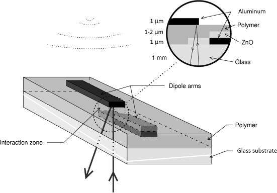
A thin layer of polymer laid on a glass substrate contains two aluminum electrodes. One of them is covered by an Al-doped ZnO layer which lengthens it until a recovering area with the second electrode. The electrodes play the role of a dipole antenna, where in the overlapping area, the electric field become very intense. ZnO:Al is an electrical conductor but is transparent to an optical beam which can penetrate in the recovering area through the glass substrate and the ZnO:Al part of the electrode and is reflected by the second aluminum electrode. The interaction occurs in the overlapping area. This is achieved by 20 mm electrodes providing a 4.7 GHz resonant dipole antenna.
To evaluate the effect of the interaction zone parameters on the structure, we used the simulator IE3D from Zealand Software. As the structure contains millimeter-scale elements on micrometer-scale thicknesses, we checked the simulator modeling varying the active layer thickness. Physically, as the gap between the electrodes decreases, the electric field increases. Results show that for thicknesses lower than 7 μm, the electric field inside the interaction zone no longer depends on layer thickness, defining here a limitation of the software. The following results are computed with a polymer thickness of 3 μm as a trade-off between software precision and component manufacturing technology.
Parameters are evaluated versus polymer thickness, overlapping zone length, and a polymer dielectric constant, assuming an incident electric field of 1 V/m, a dipole length of 20 mm, glass substrate thickness 1 mm and polymer dielectric losses = 0.075 [SUB 03]. In the simulation results presented in Figure 5.4, a field concentration appears up to 3,500 V/m for only 1 V/m incoming. The variation of the polymer dielectric constant from 2.5 to 4.5 has little influence on the frequency which varies from 4.7 GHz to 4.75 GHz. but the electric field concentration varies from 1,500 V/m to 2,500 V/m.
Note that the thinner the polymer layer is, the stronger the electric field is. However, when taking into account the electro-optic effect, this advantage is cancelled since the interaction length is reduced. Interestingly, results show that the smaller the overlapping zone is, the higher the electric field is: when it decreases from 0.3 mm to 0.1 mm, the electric field increases from 1,500 V/m to 3,500 V/m.
Figure 5.4. Effect of overlapping zone length on the device frequency response
Based on these simulations, we chose the parameters best fitting the trade-off between our realization technology and required performances. Measurements show that the PIII dielectric constant is 4.5 [GAR 07], and the maximum layer thickness we can obtain is 1.5 μm.
To let the optical beam pass into the interaction zone, we replaced the lower arm with a conductive and transparent ZnO:Al layer. However, the conductivity of this material (0.1 MS/m) has a slightly lower conductivity than aluminum. Therefore to avoid the reduction of the device performances, we chose to deposit an additional aluminum layer on this arm, excepted in the overlapping zone. As all conductive layers are deposited using a manually-aligned mechanical mask, it appeared convenient to use an overlapping zone length of 0.3 mm and a dipole width of 0.5 mm. Finally, to maximize our chances of getting a usable antenna, we implemented in each prototype, 5 antennas at a regular 5 mm distance.
5.4. Device fabrication and poling
Stacking of the conductive and active layers is realized in the following order:
– bottom aluminum electrode evaporation;
– electrode extension with Al-doped ZnO thin layer deposited by RF magnetron sputtering;
– electro-optic polymer deposition by spin-coating;
– poling and cross-linking of the electro-optic polymer;
– top aluminum electrode evaporation.
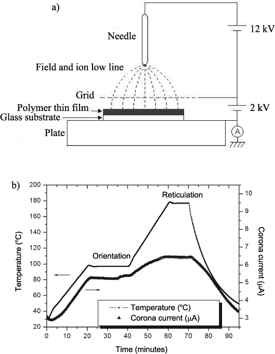
The initial random distribution of the chromophore inside polymer films results in a centrosymmetric material. In order to generate macroscopic nonlinear properties, i.e. an electro-optic effect, chromophore molecules are oriented by a Corona discharge poling method [GIA 92, HIL 94, SAM 00, SHI 00, VAN 94].
Ions generated by applying a high potential (12 kV) to a metallic needle create an electric field at the surface layer. Ion distribution is homogenized using a highly transparent metal grid (wires of 30 μm in diameter, spaced 500 μm) remained at a static potential of 2 kV, allowing a more uniform orientation of chromophores. The material is heated to increase the mobility of the chromophores, which are oriented along the created field, which then allows cross-linking reactions (Figure 5.5).
Figure 5.5. Thermal cycle and corona current during orientation and reticulation of a PIII sample
The UV-Visible absorption spectra show the efficiency of the orientation process (Figure 5.6). After poling, the maximum absorption wavelength for the π–π* transition of the chromophore moieties were blue-shifted (up to 25 nm).
In previous work, we demonstrated that this shift is assigned to the formation of an ester bond [BLA 05]. The decrease of the peak absorbance is caused by alignment of chromophore dipoles along the poling field direction.
Figure 5.6. UV-Visible absorption spectra of polymer film before (dotted line) and after (solid line) cross-linking
5.5. Experimental setup
The electro-optic measurement bench (Figure 5.7) contains a microwave part and an optical part. The microwave signal generated by a frequency synthesizer is amplified by 35 dB and emitted in the air by a horn antenna. The microwave bandwidth is from 2 to 6 GHz due to amplifier and isolator. The output microwave signal from the photodetector is measured by a spectrum analyzer Agilent A4440, at a resolution bandwidth of 1 Hz, enabling a noise level of -144 dBm. The input optical signal is generated by a DFB laser emitting at 1.31 μm with a power of +13 dBm. The optical signal at the antenna output, modulated by the electro-optic antenna, is collected by an amplified photodiode, a New Focus model 1554.
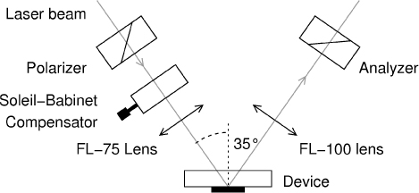
The electro-optic antenna produces a polarization modulation induced by the electro-optic effect in the active layer. This modulation is transformed into an amplitude modulation by placing the device in a polarizer/analyzer configuration, similar to the simple reflection characterization technique [TEN 90]. The optical configuration shown in Figure 5.8 is able to set the optimum bias using a Soleil-Babinet compensator, avoiding the need for voltage bias on the device.
Figure 5.7. Experimental setup
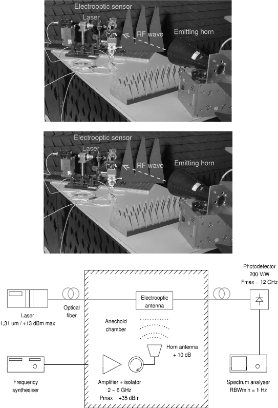
Figure 5.8. Optical setup
5.6. Results
To begin with, overlapping of the electrodes in the interaction area has been confirmed for the different realizations. All the structures show a capacitive behavior (with a capacity value between 2.2 pF and 7.6 pF), indicating that manual mask alignment has been sufficiently precise for the realization of the antenna.
The existence of the electro-optic effect has been verified by directly applying a low frequency signal (80 kHz) to the electrodes. At an electric field of 10 MV/m, corresponding to 15 V across the 1.5 μm thick polymer film, a coupling of –108 dBm has been obtained thus proving the electro-optic activity of the film.
In order to study the antenna behavior, the component has been exposed to a 4.7 GHz microwave signal for the case of coplanar and cross-planar polarization of the laser. The results of coupling can be seen in Figure 5.9 confirming the antenna action: the free-space radio frequency signal has been transferred to the optical carrier without any additional supply of energy.
Simulation shows an enhancement of the electric field in the interaction area of approximately 3,000. Thus, the field applied during the high frequency measurement (67 V/m) is concentrated to 0.2 MV/m, which is 17 dB smaller than the low frequency field at 80 kHz. Hence, the coupling of almost -122 dBm in the case of the high frequency signal corresponds to a difference of 14 dB in comparison with the low frequency attenuation of –108 dBm, which is close to the expected value.
Figure 5.9 shows detected power as a function of frequency for the case of a co-planar and a cross-planar polarization of the laser. The frequency indicated is relative to the central frequency of 4.7 GHz.
Figure 5.9. Detected signal in co-polarization and cross-polarization positions
5.7. Conclusion
We presented, in this chapter, the design of an electro-optic antenna, starting from the molecule synthesis and ending in antenna RF measurement. In this way, we showed all preparations and characterizations required to assemble a test vehicle. Several technical achievements have been obtained from the synthesis of a polymer to the fabrication of a built-in component. Although this material presents a small electro-optical response compared with the state-of-the-art polymer, we have achieved a synthesis process which allows the preparation of more than 10 grams of polymer per synthesis. The material presents good filmability, large and stable second order NLO properties, making it a good material to develop compact low cost sensors.
The antenna proposed in this chapter is a non-standard antenna which can be considered as a receive antenna fed remotely by an optical way. Then we can see this antenna either as an antenna without power supply or RF connection, or as an electrical field sensor minimizing perturbations on the surrounding electric field. Using a new polymer molecule, we designed an electro-optical sensor based on a dipole antenna structure, the fabrication process of this component is easy and low cost. This design enables us to concentrate the impinging E-field with a factor of 3,500 into the material. We realized such a device and for an impinging E-field of 67 V/m at a central frequency of 4.7 GHz, and without supplying any power to the sensor, we measured -120 dBm at the photodetector.
There is, obviously, room to improve this passive component. On the material side, new molecules can be used to enhance the electro-optical nonlinear response. On the component side, the electrode recovering zone can be reduced to increase the electric field concentration. Finally an optical waveguide across the overlapping area defined by both electrodes, and perpendicular to the electrodes could drastically increase the interaction length by at least a factor of 200.
5.8. Acknowledgments
The project was funded by Thales Systèmes Aéroportés and by the local government of Pays de la Loire. We would also like to thank Cookson Electronics for their kind preparation of mechanical masks, as well as N. Barreau and J. Kessler from the Institut des Matériaux de Nantes (UMR CNRS 6502) for depositing the antenna electrodes.
5.9. Bibliography
[AUS 88] AUSTON D.-H., NUSS M.-C., “Electrooptical generation and detection of femtosecond electrical transients”, IEEE Journal of Quantum Electronics, no. 24, pp. 184–197, 1988.
[BLA 05] BLART E., ILLIEN B., PARIS M., ODOBEL. F., “Study of the cross-linking mechanism of a copolymer containing an electrooptic chromophore”, Journal of Physical Organic Chemistry, vol. 18, no. 10, pp. 1050–1058, 2005.
[BLO 94] BLOEMBERGEN N., “Polymers in nonlinear optics: fundamentals and applications”, Int. Journal of Nonlinear Optical Physics & Materials, vol. 3, pp. 439–446, 1994.
[BOO 94] BOOGERS J.-A.-F., KLAASE P.-T.-A., DE VLIEGER J.-J., ALKEMA D.-P.-W., TINNEMANS A.-H.-A., “Crosslinked polymer materials for nonlinear optics. 1. UV-cured acrylic monomers bearing azobenzene dyes”, Macromolecules, vol. 27, pp. 197–204, 1994.
[BOS 99] BOSC D., FOLL B., BOUTEVIN B., ROUSSEAU A., “Synthesis of novel difunctional azo-dye chromophore and characterizations of a cross-linkable polymer with stable electro-optic properties”, Journal of Applied Polymer Science, vol. 74, pp. 974–982, 1999.
[BRI 91] BRIDGES W.-B., SHEEHY F.-T., SCHAFFNER J.-H., “Wave-coupled LiNbO3 electrooptic modulator for microwave and millimeter-wave modulation”, IEEE Photonics Technology Letters, vol. 3, pp. 133–135, 1991.
[BUR 94] BURLAND D., MILLER R., WALSH C., “Second-order nonlinearity in poled-polymer systems”, Chemical Reviews, vol. 94, pp. 31–75, 1994.
[DUB 98] DUBOVITSKY S., CHUYANOV V., GARNER S., STEIER W.-H., “Integrated optics photonic mixer for an all–optical implementation of a millimeter and sub–millimeter wave oscillator”, International Topical Meeting on Microwave Photonics, Technical Digest., pp. 85–86, 1998.
[EIC 89] EICH M., RECK B., YOON D.-Y., WILLSON G., BJORKLUND C., “Novel second-order nonlinear optical polymers via chemical cross-linking-induced vitrification under electric field”, Journal of Applied Physics, vol. 66, pp. 3241–3247, 1989.
[FOL 95] FOLL F., BOSC D., LIANG J., ROUSSEAU A., BOUTEVIN B., Eur. pat. appl. 641808, (France Telecom, Fr.). Application: EP, p. 20, 1995.
[GAB 04] GABORIT G., DUVILLARET L., BREUIL N., CRABOS B., LASSERRE J.-L., “Optimisation de sondes électro-optiques fibrées dédiées aux mesures hyperfréquences en espace libre”, Proceedings of European Electromagnetics, pp. 70–71, 2004.
[GAR 06] GARDELEIN A., LE TACON S., TANGUY E., BREUIL N., RAZBAN T., “Characterization of electrooptic polymer applied to microwave sensing”, International Topical Meeting on Microwave Photonics 2006, Strasbourg, France, 2006.
[GAR 07] GARDELEIN A., LE TACON S., TANGUY E., BREUIL N., RAZBAN T., “Passive electro-optic antenna using polymer material”, Electronics Letters, vol. 43, no. 9, 2007.
[GIA 92] GIACOMMETTI J.-A., OLIVEIRA JR O.-N., “Corona charging of polymers”, IEEE Transactions on Electrical Insulation, vol. 27, no. 5, pp. 924–943, 1992.
[HIL 94] HILL R.-A., KNOESEN A., MORTAZAVI M.-A., “Corona poling of nonlinear polymer thin films for electro-optic modulators”, Appl. Phys. Lett., vol. 65, no. 14, pp. 1733, 1994.
[JEN 05] JEN A., LUO J., KIM T.-D., CHEN B., JANG S.-H., KANG J.-W., TUCKER N.-M., HAU S., TIAN Y., KA J.-W., HALLER M., LIAO Y., ROBINSON B., DALTON L., HERMAN W., “Molecular design and supramolecular organization of highly efficient nonlinear optical chromophores for exceptional electro-optic”, Properties Proceedings of SPIE – The International Society for Optical Engineering, vol. 5935, pp. 593506/1–13, 2005.
[KAN 07] KANG H., FACCHETTI A., JIANG H., CARIATI E., RIGHETTO S., UGO R., ZUCCACCIA C., MACCHIONI A., STERN C.-L., LIU Z., HO S.-T., BROWN E.-C., RATNER M.-A., MARKS T.-J., “Ultralarge hyperpolarizability twisted pi-electron system electro-optic chromophores: synthesis, solid-state and solution-phase structural characteristics, electronic structures, linear and nonlinear optical properties, and computational studies”, Journal of the American Chemical Society, vol. 129, pp. 3267–3286, 2007.
[KAT 94] KATO M., HIRAYAMA T., “Photocrosslinkable azo-dye polymers for second-order nonlinear optics”, Macromolecular Rapid Communications, vol. 15, pp. 741–750, 1994.
[KEN 96] KENNEY J., NURSE J., CHON J., BINKLEY E., STILLER M., BALL D., JEN A., “NLO polymer material systems for electro-optic devices”, Materials Research Society Symposium Proceedings, vol. 413, pp. 159–164, 1996.
[KIM 07] KIM T.-D., KANG J.-W., LUO J., JANG S.-H., KA J.-W., TUCKER N., BENEDICT J.-B., DALTON L.-R., GRAY T., OVERNEY R.-M., PARK D.-H., HERMAN W.-N., JEN A.-K.-Y., “Ultralarge and thermally stable electro-optic activities from supramolecular self-assembled molecular glasses”, Journal of the American Chemical Society, vol. 129, pp. 488–489, 2007.
[KUW 92] KUWABARA N., TAJIMA K., KOBAYASHI R., AMEMIYA F., “Development and analysis of electric field sensor using LiNbO3 optical modulator”, IEEE Transactions on Electromagnetic Compatibility, vol. 34, no. 4, pp. 394–396, 1992.
[LEV 95] LEVENSON R., LIANG J., ROSSIER C., HIERLE R., TOUSSAERE E., BOUADMA N., ZYSS J., “Advances in organic polymer-based optoelectronics”, American Chemical Society Symposium Series, vol. 601, pp. 436–55, 1995.
[LIA 95] LIANG Z., DALTON L.-R., GARNER S.-M., KALLURI S., CHEN A., STEIER W.-H., “A cross-linkable polyimide for second-order optical nonlinearities”, Chemistry of Materials, vol. 7, pp. 941–944, 1995.
[LIN 92] LIN J., HUBBARD M., MARKS T., “Poled polymeric nonlinear optical materials exceptional second harmonic generation temporal stability of a chromophore-functionalized polyimide”, Chemistry of Materials, vol. 4, pp. 1148–1150, 1992.
[MAN 91] MANDAL B.-K., CHEN Y.-M., LEE J.-Y., KUMAR J., TRIPATHY S.-K., “Cross-linked stable second-order nonlinear optical polymer by photochemical reaction”, Applied Physics Letters, vol. 58, pp. 2459–2460, 1991.
[MAR 94] MARDER S., PERRY J., “Nonlinear optical polymers: discovery to market in 10 years?”, Science, vol. 263, pp. 1706–1707, 1994.
[MAR 95] MARKS T., RATNER M., “Design, synthesis, and properties of molecule-based assemblies with large second-order optical nonlinearities”, Angewandte Chemie International Edition, vol. 34, pp. 155–173, 1995.
[MAR 97] MARDER S., KIPPELEN B., JEN A., PEYGHAMBARIAN N., “Design and synthesis of chromophores and polymers for electro-optic and photorefractive applications”, Nature, vol. 388, pp. 845–851, 1997.
[MIL 95] MILLER R., BURLAND D., JURICH M., LEE V., MOYLAN C., THACKARA J., TWIEG R., VERBIEST T., VOLKSEN W., “Donor-embedded nonlinear optical side chain polyimides containing no flexible tether: materials of exceptional thermal stability for electrooptic applications”, Macromolecules, vol. 28, pp. 4970–4974, 1995.
[PAR 01] PARK L.-S., KIM S.-J., CHOI S.-Y., KIM G.-H., “Synthesis of photocrosslinkable nonlinear optic polyimides and electro-optic properties”, Molecular Crystals and Liquid Crystals, vol. 357, pp. 11–25, 2001.
[PEN 94] PENG Z., YU L., “Second-order nonlinear optical polyimide with high-temperature stability”, Macromolecules, vol. 27, pp. 2638–2639, 1994.
[RIB 00] RIBEIRO P.-A., BALOGH D.-T; GIACOMMETTI J.-A., “Physics and chemistry of partial discharge and corona. Recent advances and future challenges”, IEEE Trans. on Dielectrics and Electrical Insulation, vol. 7, no. 4, pp. 572–577, 2000.
[SAM 00] SAMYN C., VERBIEST T., PERSOONS A., “Second-order nonlinear optical polymers”, Macromolecular Rapid Communications, vol. 21, pp. 1–15, 2000.
[SHI 00] SHI W., FANG C., XU Z., PAN Q., GU Q., XU D., WEI H.,YU J., “Physics and chemistry of partial discharge and corona. Recent advances and future challenges”, Solid State Communications, vol. 113, no. 9, pp. 483–487, 2000.
[STE 96] STEIER W., KALLURI S., CHEN A., GARNER S., CHUYANOV V., ZIARI M., SHI Y., “Applications of electrooptic polymers in photonics”, Materials Research Society Symposium Proceedings, vol. 413, pp. 147–157, 1996.
[SUB 03] SUBRAMANYAM G., MATHALA P., CHEVALIER C., DAVIS A., YANEY P., GROTE J., “Microwave characterization of electrooptics polymers”, Material Research Society Symposium Proceedings, vol. 734, pp. 249–254, 2003.
[TEN 90] TENG C.-C., MAN H.-T., “Simple reflection technique for measuring the electro-optic coefficient of poled polymers”, Applied Physics Letters, vol. 56, pp. 1734, 1990.
[TSU 95] TSUTSUMI N., YOSHIZAKI S., SAKAI W., KIYOTSUKURI T., “Nonlinear optical polymers. 1. Novel network polyurethane with azobenzene dye in the main frame”, Macromolecules, vol. 28, pp. 6437–6442, 1995.
[VAN 94] VAN BRUNT R.-J., “Physics and chemistry of partial discharge and corona. Recent advances and future challenges”, IEEE Transactions on Electrical Insulation, vol. 1, no. 5, pp. 761–784, 1994.
[YAN 94] YANG S., PENG Z., YU L., “Functionalized polyimides exhibiting large and stable second-order optical nonlinearity”, Macromolecules, vol. 27, pp. 5858–5862, 1994.
[YU 92] YU L., CHAN W., BAO Z., “Synthesis and characterization of a thermally curable second-order nonlinear optical polymer”, Macromolecules, vol. 25, pp. 5609–5612, 1992.
1 Chapter written by Annabelle SCARPACI, Sylvain LE TACON, Arnaud GARDELEIN, Fabrice ODOBEL, Errol BLART, Dominique AVERTY, Hartmut GUNDEL, Nicolas BREUIL, Tchanguiz RAZBAN and Eric TANGUY.