
Chapter 9
Wideband Antennas and Artificial
Magnetic Conductors1
9.1. Introduction
Metamaterials have recently been applied to antennas even though in the past they have already been used under other names (e.g. corrugated horns). This generic term covers a variety of definitions: left-handed material (LHM), electromagnetic band gap (EBG) material, artificial magnetic conductor (AMC), high impedance surface (HIS), etc. A common thread to all these definitions is that these materials derive their unique properties, not from their composition, but from their structure. They are mostly composed of a periodic arrangement of materials. This spatial periodicity naturally induces a spectral selectivity and then you can legitimately ask the question: can I expect some improvements to my wideband antenna system using these metamaterials?
The aim of this chapter is to provide some answers. At first, we will specify the nature of the metamaterial we will use, in this case AMC, without and with losses.
The initial objective of this work is the thickness reduction of unidirectional planar antennas. Usually unidirectionality is achieved using a cavity filled with thick absorbent. The idea is to replace the bulky absorbent with a thin absorbent or a particular reflector closest to the antenna and wideband. After having characterized them, we will associate some AMC with antennas which have bandwidths ranging from several percent to several tens of percent to demonstrate the improved performance and reduced overall thickness that it is now possible to have.
9.2. Wideband antenna and metamaterial
9.2.1. How to design a wideband antenna?
There are several strategies for designing a wideband antenna. The choice of the design process is dependent on the particular application and available space for the antenna thus implying the operating frequency and the desired gain.
9.2.1.1. Physical approach
A classical technique to design a wideband antenna is to associate intrinsic resonances of the radiating element. Coupling and proximity between these resonances can help to define a wideband antenna. The example below (Figure 9.1) is a good illustration.
This antenna, whose upper part is a triangular metallic plate, is fed with F-probe [LEP 04]. The form of this probe enables the generation of two quarter-wavelength resonances (it is a monopole like structure). These two resonances are later coupled with the resonance of the upper triangular part. Mastering these three resonances enables us to obtain an antenna bandwidth close to an octave.
Figure 9.1. F-probe triangular patch antenna
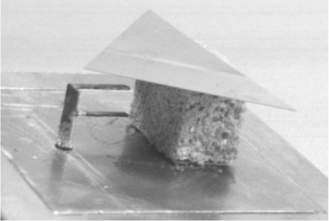
This is a standing-wave antenna; the radiated energy is the energy lost by the resonator.
And now if we want to design an antenna realizing a direct transfer of antenna input power toward free space, then we must realize a traveling-wave device (Figure 9.2).
Figure 9.2. TEM horn antenna
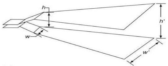
A transverse electromagnetic (TEM) horn is a device that converts a transmission line composed of two parallel strips into a horn. The transition between the transmission line and the horn aperture is realized by gradually adjusting the characteristic impedance of the transmission line (50 Ohms) to the free space impedance (377 Ohms). TEM mode of the transmission line can then lead to a wideband antenna.
9.2.1.2. Geometrical approach
Other techniques are available to realize wideband antennas:
– Rumsey’s principle [RUM 57], derives that an aerial fully defined by the angles is a frequency independent antenna and therefore inherently wideband.
– Babinet’s principle connects the input impedance of a structure to the input impedance of the complementary structure. The design of a self-complementary structure fixes the antenna’s input impedance to half the free space impedance (60 π Ohms) [DUB 76].
9.2.2. What kind of metamaterial?
9.2.2.1. Context
The term metamaterial means whole artificial composites that exhibit electromagnetic properties not found in natural materials. This is also known as lefthanded material (LHM), electromagnetic band gap (EBG) material, artificial magnetic conductor (AMC), high impedance surface (HIS), etc.
These metamaterials are usually periodic structures, dielectric or metal, which behave as homogeneous materials. This periodicity leads to resonant structures that may seem incompatible with a wideband application.
The purpose of this chapter is not to define all these terms but to show that it is possible to use these new materials to optimize the performance of a wideband antenna.
9.2.2.2. Problem
To design a unidirectional antenna, which is the case for many platforms, the antenna must radiate outward and preserve the interior of any electromagnetic pollution. The antenna is usually backed by a reflector or absorbent cavity.
Figure 9.3. Unirectional antenna above cavity (a); and PEC (perfect electric conductor) (b)
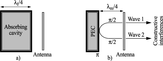
The solution with the absorbing cavity is simple but half of the radiation is lost (Figure 9.3a). Absorbents are heavy and features are difficult to reproduce. Moreover the cavity is sized at a quarter of a wavelength at the lowest operating frequency which becomes a problem for low frequency applications.
Another efficient technique is to use a reflector composed of a very good electrical conductor to retrieve the radiation lost in the first solution (Figure 9.3b). This technique is optimal at the middle of the bandwidth where a constructive interference phenomenon is obtained by placing the reflector at a quarter wavelength (at the center frequency) from the antenna. This solution is inherently a limited bandwidth and can rarely exceed the octave [BEG 96].
It therefore appears difficult to conceive of combining bandwidth and compactness. But among metamaterials, the so-called artificial magnetic conductors (AMC) have remarkable characteristics. While a highly conductive metal and reflected waves impose a phase shift of Pi, the magnetic conductors do not introduce a phase shift (Figure 9.4).
Figure 9.4. Unidirectional antenna with AMC
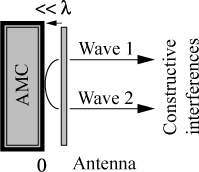
It then becomes possible to position the antenna closest to the new reflector. The antenna is unidirectional and thin. So now it is time to build this artificial magnetic conductor.
9.3. How to characterize an artificial magnetic conductor?
9.3.1. Principle
A classical method which was proposed by Sievenpiper [SIE 99] to characterize the high impedance surface is the reflection phase method (RPM) (there is equivalence between a high impedance surface and an artificial magnetic conductor). This method involves illuminating the surface to be characterized using a plane wave at normal incidence. It then compares the phase difference between the incident wave and the reflected wave.
Constructive interference occurs when the phase difference is between – π/2 and + π /2 and this defines the bandwidth of the artificial magnetic conductor.
9.3.2. Example
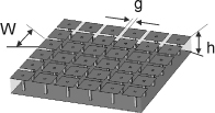
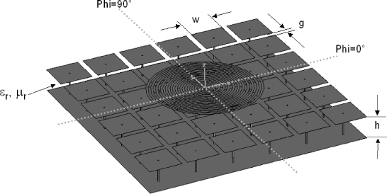
Figure 9.5 presents an artificial magnetic conductor composed of an array of “mushrooms” [SIE 99]. These metal plates are connected to the ground plane via holes.
Figure 9.5. “Mushroom” structure (W=8 mm g=1 mm h=4.8 mm εr=1)
Then we draw the phase diagram according to the principle in the preceding section.
Figure 9.6. Phase diagram of the “mushrooms” structure (dimensions given in Figure 9.5)
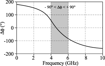
Closer analysis shows that the bandwidth of the structure is particularly linked to the height of the mushrooms (h) and that this therefore leads to an increase in the total thickness of the antenna to increase the bandwidth. It is therefore difficult to expect a very wide bandwidth with this structure.
On the other hand, we must remember that we consider here only the reflector without the antenna and illuminated by a plane wave at normal incidence. We must now analyze what happens when you place an antenna above that particular reflector.
9.4. Narrow bandwidth antenna above an AMC
9.4.1. Dipole and AMC
First of all, we will analyze what happens when we just place a dipole above an AMC. We use the case presented in [YAN 03] and recalled in Figure 9.7.
Figure 9.7. Dipole above “mushrooms” AMC (W=0.12 λ 12GHz, g=0.02 l 12GHz, h=0.04 λ 12GHz, r=0.005 λ12GHz dipole placed at 0.02 λ12GHz above AMC εr=2.2)
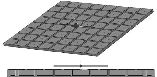
Figure 9.8. Magnitude of the reflection coefficient of the dipole placed above the “mushrooms” AMC for two dipole lengths (0.48 λ 12GHz and 0.36 λ 12GHz)
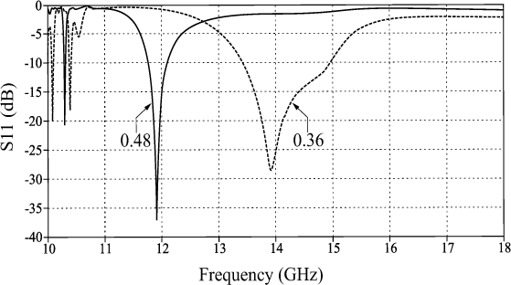
The set is analyzed with the Microwave Studio software (CST), this tool will be used for all simulations presented. We initially consider the matching of the antenna shown here by the magnitude of the reflection coefficient (| S11 |) plotted for two dipole lengths (0.48 λ12GHz and 0.36 λ12GHz). The single dipole was initially designed to operate at 12 GHz, so all measurements are referenced to this wavelength.
AMC has been initially sized so that the dipole is used, i.e. matched to the usual criterion to –10dB. A first observation is that the dipole in the presence of AMC has a higher bandwidth for a length of 0.36 λ12GHz at the half-wave resonance. These results are quite consistent with those presented in [YAN 03].
If we now separately characterized the AMC using the method of the phase diagram, what do we observe?
Figure 9.9. Phase diagram of the AMC “mushrooms” (dimensions given in Figure 9.7)
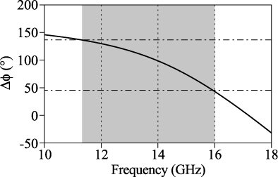
The gray area is the area where the dipole is matched in the presence of AMC (Figure 9.8). It is significant to note that this bandwidth does not correspond to previously identified bandwidths, which leads to constructive interferences. This new frequency bandwidth is thus defined by a phase difference of between - 3 π / 4 and + π / 4. The null phase is obtained at a frequency of 17 GHz where the dipole is not matched.
The first conclusion is that there is interaction between the dipole and AMC and they cannot develop independently of one another.
We must also remember that the distance between AMC and the dipole is small (0.02 λ12GHz) and interaction is especially important when this distance is small.
9.4.2. Dipole and PMC
To understand more precisely the effects shown in the previous section we will now study what happens when you approach a dipole of a perfect magnetic conductor (PMC). To do this we will use the image’s principle and replace the PMC with the image’s dipole.
Figure 9.10. Influence of the image’s dipole on the matching of the fed dipole
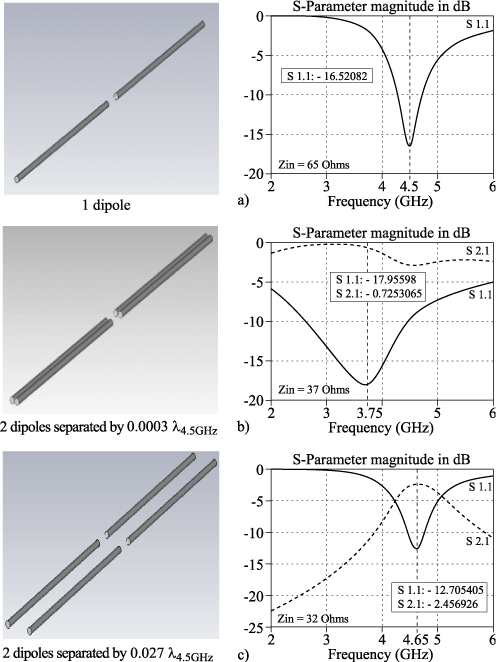
Three configurations are studied: the single dipole, the dipole and its image separated by 0.0003 λ4.5GHz and the dipole and its image separated by 0.027 λ4.5GHz.
The single dipole is resonant at 4.5 GHz. When the dipole is very close to the PMC (Figure 9.10b) there is a strong coupling between the two dipoles and a change in the input impedance (halving) and a shift of the resonance to lower frequencies. Now if we move the dipole while remaining close to PMC (Figure 9.10c), we observe that there is still coupling between the two dipoles but this time the resonance is close to the dipole alone.
It is shown that there is a trade-off between the distance at which you want to place the reflector and control the radiating characteristics of the antenna.
9.5. Wideband antenna placed above an AMC
9.5.1. Archimedean spiral above an AMC
We will now consider an antenna quasi-independent of frequency placed above the structure presented in the previous paragraphs. The geometry of the antenna and its reflector is given in Figure 9.11.
Figure 9.11. Antenna description: “mushrooms” AMC: W=36 mm, g=6 mm, h=24 mm, εr=1. Spiral: ø=1.07λ1GHz/π=102. 5mm, ws=2.5 mm, d=6 mm (spiral-AMC distance) (0.018λ900MHz)
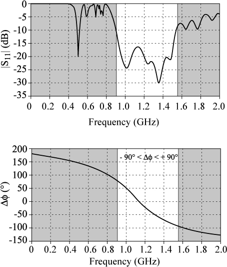
The matching of the complete structure is given in Figure 9.12. The bandwidth obtained is wider (53.6%) and it is interesting to note that this coincides with the bandwidth deduced from the phase diagram (with criterion − π/2 < Δφ < + π /2).
Figure 9.12. Matching of the complete antenna (“mushrooms” AMC + spiral) and phase diagram of the “mushrooms”AMC
This good result is also validated by the quality of the radiation patterns (Figure 9.13).
The radiation pattern produced by this antenna is stable over the bandwidth (a gain of 7 dB was also measured).
In conclusion, we have a thin wideband antenna (0.09λ900MHz) for which the AMC placed at 0.018λ900MHz does not deteriorate the quality of the isolated antenna.
Figure 9.13. Normalized radiation patterns of the complete antenna (spiral + “mushrooms” AMC)
9.5.2. Bow-Tie antenna above an AMC
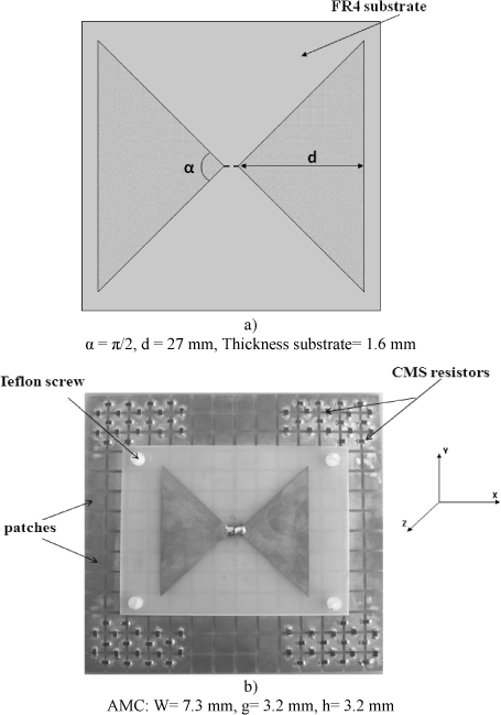
Now consider a wideband linearly polarized antenna: bow-tie. We will further simplify the design by removing the via from the reflector (AMC “patches”) [THI 09].
The antenna is first designed alone (Figure 9.14a) to be matched around 175 Ohms between 3 and 5 GHz. The dielectric used is FR4.
Figure 9.14. Bow-tie alone (a) and bow-tie with AMC “patches”(b)
The AMC is sized to have a phase difference Δφ =0° at 4 GHz. It then combines the antenna and the AMC separated by a distance of 0.016λ3GHz. However, the results are not there and the behavior of the antenna is highly degraded.
Figure 9.15. Matching of bow-tie + AMC “patches” and phase diagram of AMC “patches”
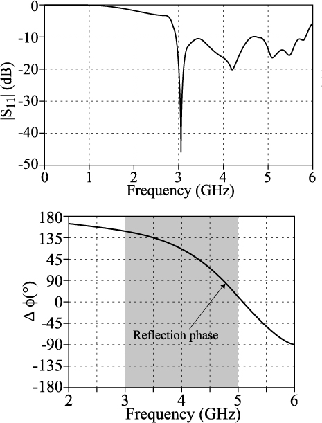
We then used the findings of section 9.4.1 to calculate the useful band of the AMC at a higher frequency. Indeed, after optimizing the antenna is now matched in the desired bandwidth (3–5 GHz) and when we observe the phase diagram of the AMC, it is found that the frequency bandwidth corresponding to the criterion −135° < Δ φ < +45° is almost in the middle of the bandwidth of the antenna (Figure 9.15).
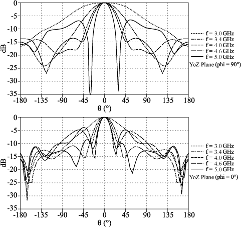
The radiation patterns are shown in Figure 9.16. The gain of this antenna varies from 3.3 to 9.3 dB from 3 GHz to 5 GHz. We also observe that the radiation degrades at high frequencies. These impairments were minimized by using lumped resistors placed at the periphery of the antenna (Figure 9.14b).
Figure 9.16. Normalized radiation patterns of the complete antenna (bow-tie + AMC “patches”)
The total thickness of the antenna is 0.05λ3GHz and the distance between the antenna and the AMC is 0.016λ3GHz (inside FR4: 0.032λ3GHz).
It may be noted that the distance between the antenna and AMC is similar to the distance chosen for the Archimedean spiral antenna. However, we have seen that there was more damage caused by the presence of AMC on the antenna radiation characteristics. You cannot really attribute this degradation to the polarization of the antenna (in one case circular and linear in the other) but more likely the nature of the radiating element. Indeed, the behavior of the Archimedean spiral is characterized by the displacement of an electric field density ring depending on the frequency, which leads to a localized area covered by the currents. For the bow-tie antenna, current distributions are broader in particular for high frequencies and thus there is more interaction between the antenna and the AMC.
9.6. Very wideband antenna placed above an AMC
From the previous results we can deduce that it will be difficult to combine wideband, high gain and low thickness for a unidirectional antenna. In the following part, we will release the stress of gain/efficiency and present a solution with a very thin and very wide bandwidth [SCH 06].
Figure 9.17. Spiral antenna and “loaded patches” AMC description
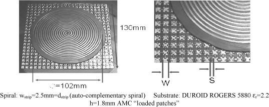
The description of the Archimedean spiral antenna is given in Figure 9.17 and the radiation characteristics are given in Figures 9.18 and 9.19. All metallic patches of the AMC are connected to each other by a CMS lumped resistor (“loaded patches” AMC). This achievement is an outcome of the collaboration initiated in 2002 between Thales Airborne Systems and TELECOM ParisTech.
Figure 9.18. Matching and gain of the spiral antenna above “loaded patches” AMC
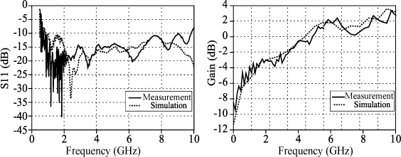
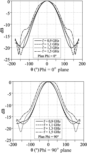
Figure 9.19. Radiation patterns in the planes Phi=0° and Phi=90° for the spiral antenna above “loaded patches” AMC
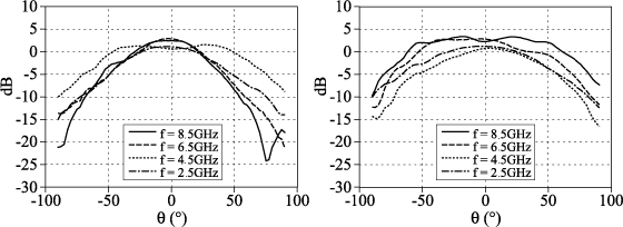
This antenna is very thin (0.012λ1GHz) is characterized by a bandwidth close to the decade. The gain and radiation patterns (Figures 9.18 and 19) are comparable to those obtained with an antenna backed with an absorbent cavity.
Somehow, this poor artificial magnetic conductor behaves as a good absorber that is advantageously very thin. This patented solution has reduced by a factor of 10, the thickness of antennas commonly used with an absorbing cavity.
9.7. Conclusions
To conclude this non-exhaustive presentation, we can say that the reflection phase method to characterize an artificial magnetic conductor is not sufficient but necessary and quick. This characterization is performed using a plane wave at normal incidence which is a special case.
The combination antenna placed above an AMC must then be done carefully. It should take into account the following information:
– The nature of the antenna: resonant antenna, traveling wave antenna, independent of frequency. This nature will provide information on current distributions that need to be controlled.
– The minimum acceptable distance between the antenna and AMC. It should therefore be assessed prior to the coupling between the antenna and its image to anticipate the impact of AMC on the matching operating frequency.
– Apart from the bandwidth of the AMC, implement strategies to minimize the spread of currents on the AMC (loads, periodicity break, etc.).
Finally, it is worth remembering that it is always difficult to escape the compromise: gain/size/bandwidth.
9.8. Acknowledgments
A big thank you to those researchers involved directly or indirectly with the subject: Ludovic Schreider, Fabrice Linot, Michael Grelier, Aïta Thior, Raquel Planas with the support of Michel Soiron, Bernard Perpère, Christian Renard, Anne Claire Lepage, Jean-Marc Lemener, Michèle Labeyrie, Stéphane Mallégol and Michel Jousset.
9.9. Bibliography
[BEG 96] BEGAUD X., Analyse d'antennes et de réseaux d'antennes large bande et bipolarisation par une méthode d'éléments finis de surface, Thesis, University of Rennes 1, France, 1996.
[DUB 76] DUBOST G., ZISLER S., Antennes à large bande, Masson, 1976.
[LEP 04] LEPAGE A. C., BEGAUD X., “A compact ultra wideband triangular patch antenna”, Microwave and Optical Technology Letters, vol. 40, no. 4, February. 2004.
[RUM 57] RUMSEY V. H., Frequency Independant Antennas, 1957 IRE National Convention Record, pt. 1, pp. 114–118, 1957.
[SCH 06] SCHREIDER L., Antennes à très large bande passante et de très faible épaisseur. Application à l’intégration d’antennes dans des structures de porteurs dans la bande 100MHz-1GHz, PhD Thesis, ENST, 2006.
[SIE 99] SIEVENPIPER D. F., High-impedance electromagnetic surfaces, PhD Thesis, University of California, Los Angeles, USA, 1999.
[THI 09] THIOR A., LEPAGE, A-C., BEGAUD X., “Low profile, directive and ultra wideband antenna on a high impedance surface”, EuCAP 2009, Berlin, Germany, 2009.
[YAN 03] YANG F., RAHMAT-SAMII Y., “Reflection phase characterizations of the ground plane for low profile wire antenna applications”, IEEE Transactions on Antennas and Propagation, vol. 51, no. 10, pp. 2691–2703, October 2003.
1 Chapter written by Xavier BEGAUD.