
Chapter 16
Automatic Take-off and Landing System1
16.1. Introduction
The recent use of unmanned vehicles in the air traffic domain is requiring the development of new safety functions. In particular, it is necessary to setup dedicated systems to deal with automatic take-off and landing management. These new systems must be able to guarantee safe landing and take-off of unmanned aircrafts, regardless of the environment conditions. Consequently, they must rely on sensors that have the capability to localize the in-flight aircraft with high accuracy, especially when it is very close to the ground. Such sensors must be robust, easy to install, and as cheap as possible.
Considering this issue, Thales has developed a new radar, called “Magic Atols” within the framework of the “Watchkeeper” program.
This radar is using low cost technologies and its design has been optimized in order to keep the electronic functions simple and to minimize the number of components. The selected architecture is combining sparse antenna array, digital waveform generation, solid state transmission and digital reception technologies.
Thanks to the combination of digital beamforming and interferometer techniques, this architecture does not involve the use of expensive radio frequency (RF) nor mechanics components. It also permits fast deployment on the field, and offers high operating robustness, thanks to the redundancy of radar channels.
Finally, the antenna array spatial sampling enables the implementation of powerful and original processing, resulting in very accurate localization at low grazing angles.
This chapter presents the main features and the architecture of the radar, and the performances that have been achieved through this new concept.
16.2. State of the art
Several technologies are today available to manage automatic take-off and landing of unmanned aerial vehicles. For diverse reasons, the commonly used solutions are not completely satisfactory.
A first kind of equipment uses GPS (global positioning system) or DGPS (differential global positioning system). Unfortunately, this solution raises the problem of the availability and the continuity of the service. In addition to that, its vulnerability to jammers may be critical.
A second kind of equipment uses laser technology. This technology suffers from important propagation losses in bad weather conditions, and does not for this reason guarantee permanent availability. Moreover, as the laser beam is very narrow, a great number of scans is necessary to detect a target, increasing the research cycle duration. In addition, an accurate alignment of the laser beam with regard to the runway is compulsory.
A third category of equipments is using millimeter wave radar technology. Due to narrow beam-width and high transmitted frequency, this technology is suffering at a lower level of the same drawbacks as the laser technology. This is true for research cycle time, weather limitation and accurate positioning as well.
Moreover, these radars are using servomechanisms to point the antenna beam towards the target, making the system expensive and more difficult to operate.
In particular, in the case of multiple targets, it is necessary to share the time and to manage switching from one target to another, with the risk of losing the tracks.
Finally, due to high propagation losses in the millimeter wave domain, these radars must be operated in association with a cooperative onboard transponder, which is continuously transmitting. The use of such a transponder makes the UAV indiscreet, and increases the vulnerability to electronic failure, resulting in poor reliability of the global system.
16.3. MAGIC ATOLS main features
The system is composed of the following devices:
– A ground-based radar, placed at the edge of the runway, performing both distance and angle localization of the UAV. The measurements are obtained at the same time through skin echo detection and from an onboard beacon transmission.
– A beacon aboard the aircraft, which provides a punctual reference position to the radar through an RF continuous transmission.
– A ground-based beacon, located at the edge of the runway close to the touch down point, at a predetermined position with respect to the radar. This beacon allows us to refine the UAV positioning, the angular position of the UAV being estimated by the radar processing through differential measurement between the onboard beacon and skin echo position, and the ground beacon position.
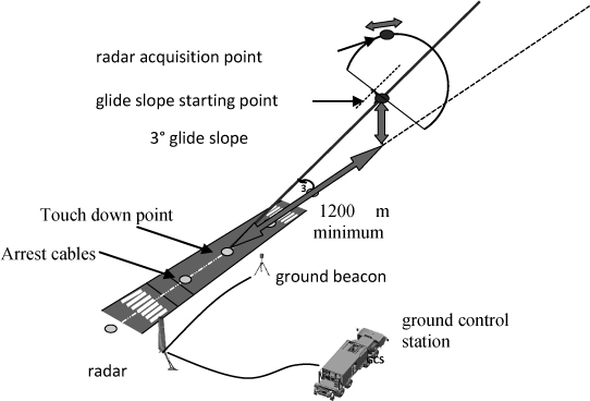
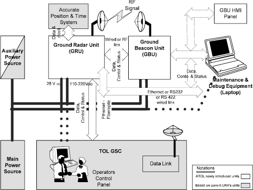
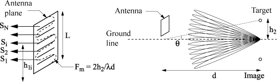
Figures 16.1 and 16.2 respectively represent the conditions of deployment and the architecture of the ATOLS system on the ground.
Figure 16.1. Conditions of deployment
The system is operated from a ground control station, which transmits to the UAV its estimated position through a dedicated data link.
The radar has a large and fixed antenna beam, allowing single or multiple instantaneous detection and tracking within the whole angular domain. This way to proceed is much more efficient than mechanical or electronic scanning, which are time demanding.
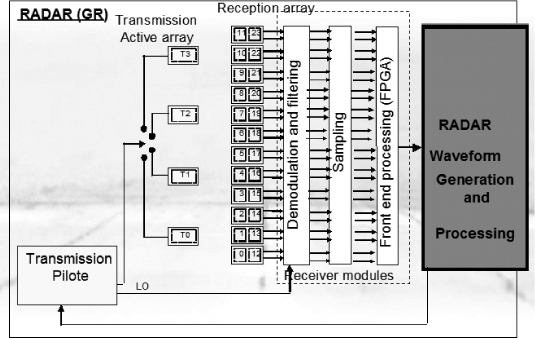
Figure 16.2. General architecture
The radar operates in the X-band, and makes use of low-cost technologies and architectures:
– simultaneous transmit and receive homodyne architecture;
– patch printed antennas;
– low power solid state transmitter;
– digital direct frequency synthesis (DDS).
Finally, it is provided with a dedicated and innovative processing, resulting in a very accurate angle measurement at low grazing angles. Thanks to this processing, a one milliradian class of accuracy is achieved during final approach, such performance being unreachable with conventional techniques.
16.4. Radar features
16.4.1. Functional performances
During the glide slope approach, the UAV enters the lobe of the radar antenna. In a first step, it is detected and identified through the beacon transmitted signal. In a second step, the radar locks on the aircraft skin echoes and initiates a tracking sequence. This process typically starts at an altitude of 850 feet during the landing phase, as the aircraft is 5,000 meters from the radar. Before the initialization of the radar tracking, the position of the UAV is estimated by classical means, such as GPS localization.
As the final approach is underway, the accuracy of localization is continuously improving. The angular measurement accuracy reaches 1 milliradian just before landing, as the aircraft is flying a few meters above the ground.
The functional performances of the MAGIC ATOLS system are as follows: – detection distance > 10 km;
– radar lock-on distance > 5 km;
– localization accuracy:
- distance: 1 m,
- azimuth and elevation angle: 1 mrd during final approach,
- velocity: 0.1 m/s,
– refresh rate: 20 Hz;
– latency time < 100 ms.
16.4.2. Wave form
The radar operates in continuous mode with simultaneous transmission and reception.
The wave form includes two interleaved sequences:
– The first sequence is devoted to the “active” mode. During this sequence, the radar is transmitting in the direction of the UAV, detects it and estimates its position and its speed from the radar echo. During this phase, a FMCW signal is used (frequency modulated continuous wave).
– The second sequence corresponds to the “passive” mode. During this sequence, the radar is successively listening to the air beacon signal and to the ground beacon signal, in order to calculate the UAV coordinates with regard to the touch down point. The radar local oscillator is locked on the beacon frequencies through a phase locked loop.
Thanks to this dual operation mode, the radar utilizes two independent channels to provide the localization of the UAV in a redundant way.
16.4.3. Elevation Angular localization
The angular elevation coverage extends over a domain of 15°. This domain is divided into two parts, each part corresponding to specific processes:
– at low angles, typically from 0° up to 5°:
- dedicated interferometer processing, fitted to cope with the ground reflections,
- this process applies in particular in standard glide slope configuration, (3°) and in any case during the final approach, as the localization accuracy must be at its best;
– at higher angles, typically from 5° up to 15°:
- digital beam forming (DBF) and monopulse processing,
- this processing is activated in particular during constant altitude flights.
Both processes are applied synchronously to the air beacon received signal and to the radar skin echo, providing high levels of robustness and safety to the system.
16.4.4. Low elevation processing
16.4.4.1. Ground reflection issues
The problem of electromagnetic wave reflection on the ground is well known by radar designers. These reflections affect the performances of the sensor in two ways:
– deterioration of the detection sensitivity, as the ground reflected signal may be in opposition of phase with the direct signal;
– deterioration of the angular localization, since the coherent combination of the direct and reflected signals may create phase and amplitude aberrations on the receiving antenna.
Such a situation is depicted in Figure 16.3.
Figure 16.3. Low elevation angle phenomena
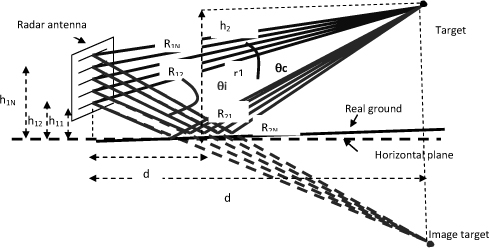
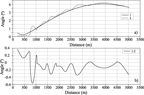
These degradations can be critical for ground to air tracking radars during the detection phase and in very low-altitude tracking situations. Figure 16.4 shows an example of the elevation measurement disturbance due to ground reflections, as standard radar processing is employed.
Figure 16.4. Disturbance on elevation measurement caused by ground reflections: a) the continuous curve referred to as 1 corresponds to the measurement without ground reflection, the continuous curve corresponds to the measurement with ground reflection; b) the curve represents the measurement error, resulting from curve 1 — curve 2
The common solutions that are usually implemented to fix these issues consist of filtering out the reflected signal through the radar antenna itself.
This is achieved by minimizing the contribution of the unwanted signals thanks to an optimized orientation and to an increased directivity of the radar antenna beam.
Unfortunately, this method requires very high directivity antennas and very precise beam orientation as well. The reduction of the beam width generates as a direct consequence a proportional increase in the antenna size. However, the dimensions of the antenna are very often limited from constraints induced by the installation site. It is indeed difficult to install a very large antenna at the border of a landing runway, for practical and safety reasons.
As a complement to these large antennas, complex and dedicated algorithms can be implemented, such as high resolution adaptive algorithms. These algorithms require important processing means, and are sensitive to the validity of the propagation model that is used, especially concerning the mutual coherency of the direct and reflected signals. Consequently these algorithms may not be robust and are difficult to implement in real life.
16.5. MAGIC ATOLS processing for low elevation measurement
16.5.1. Principle
The basic idea is to use the reflections on the ground, instead of trying to remove them. The challenge thus is to maximize the reflections:
– by using a wide field of view antenna, in order to illuminate the ground through the antenna main lobe;
– by using horizontal polarization, in order to increase the amplitude of the reflection coefficient and to keep it stable in amplitude and phase in a large angular domain.
The goal is then to measure the differential angle between the target and its image, instead of trying to directly measure the target elevation angle, as it is done in conventional processing.
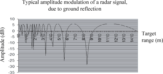
The summation of the direct and reflected signals generates interference waves, resulting in a sinusoidal amplitude modulation of the transmitted signal. This modulation affects the propagation range, according to the graph presented in Figure 16.5.
This modulation is also detectable on the radar antenna, provided that a spatial sampling is operated in the antenna vertical plane through independent subantennas.
Figure 16.5. Amplitude modulation of the electromagnetic field as a function of range in the presence of ground reflections
This is achievable by setting up a multiple access antenna array, each access being connected to an independent receiver, these receivers being distributed along the vertical axis of the antenna, as shown in Figure 16.6.
Figure 16.6. Receiving multiple sub-array
The computation of the amplitude modulation frequency Fm along the vertical axis of the antenna allows us to measure the elevation angle of the target: θ =h2/d.
This calculation is achieved by looking for the maximum correlation of the received signal with regard to a set of possible replicas, the modulation signal following the formulation below:
![]()
where:
– |Si| is the amplitude of the received signal on the sub array of rank I;
– h1i is the height of the phase center of sub array i with regard to the reflection plane;
– h2 is the height of the target with regard to the reflection plane;
– ρ is the magnitude of the reflection coefficient of the ground (ρ= 1 in H polarization);
– λ is the wavelength of the transmitted signal (3.2 cm);
– d is the target distance from the radar;
– φ is a phase depending on the slope of the reflection plane;
– θ is the target elevation angle with regard to the radar.
Figure 16.7. a) Sampled modulation signal along the vertical axis of the antenna; b) result of the correlation process with all the possible replicas
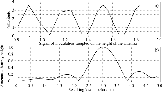
Figure 16.7 depicts the modulation signal after sampling on the vertical axis of the antenna, and the result of the correlation process with all the possible replicas.
For an antenna of length L, the resolution of the correlation process can be expressed as: ΔΘ = λ / 2L. The optimal measurement accuracy can be expressed according to the signal-to-noise ratio S/N by:
![]()
As an example, when considering an antenna of height L=1.2 m and a signal-to-noise ratio S/N of 20 dB, the correlation process will lead to a measurement accuracy σθ better than 1 mill radian.
16.5.2. Antenna architecture
The antenna is constituted at the transmitter part of four sub-arrays, each covering 10° in elevation by 20° in azimuth, and at the receiver part of a sparse array.
Figure 16.8. Antenna architecture
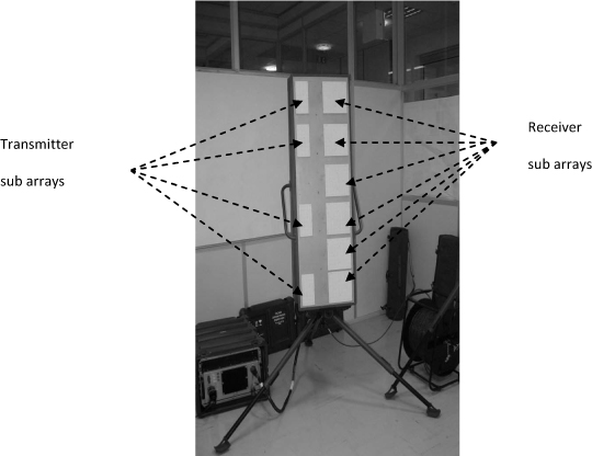
The receiver sparse array itself consists of 24 sub-arrays, each covering 20° in elevation by 20°in azimuth, and is distributed in two identical rows of 12 sub-arrays.
As the antenna is tilted by 5° towards the rear, the angular coverage domain is finally limited to 15° with respect to the ground plane.
In order to permanently optimize the signal-to-noise budget, one of the four transmitting sub-arrays is selected at each transmission period, according to the interference pattern that is observed on the receiving antenna (see Figure 16.7).
Each receiver sub-array is connected to a digital receiver which performs front processing. An FPGA component is used to perform upstream filtering through an FFT process: pulse compression of the radar echo in the active radar mode and pass band filtering of the beacon signal in the passive mode. All the other calculations are operated through a dedicated processing card. Digital beamforming, Doppler processing, detection, and 3D localization are performed at this level. This card is used for tracking and data processing.
The radar architecture is represented in Figure 16.9.
Thanks to the receiver redundancy, the system provides safe landing capability, even in the case of failure involving one or several receiving channels.
Figure 16.9. Radar synopsis
16.6. On the field experimental results
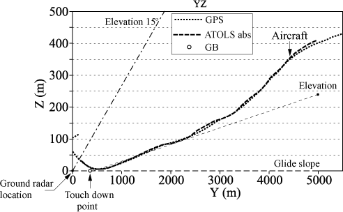
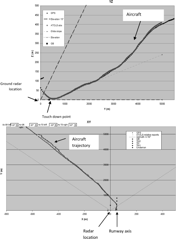
The curves represented in Figures 16.10 and 16.11 illustrate an example of aircraft tracking results. The flight trajectory corresponds to a typical approach for landing, followed by a “touch and go” maneuver at a distance of 400 m from the radar.
The figures show the trajectories obtained from DGPS measurements (1 point each second) marked as GPS; and the trajectories estimated by the radar (1 point each 50 ms), marked as ATOLS abs.
These results demonstrate fine correlation between the DGPS and radar estimations, the radar tracking being even more precise than the DGPS during acceleration phases, thanks to much higher refresh rate.
All the test flights performed in various trajectory configurations and various ground conditions have demonstrated the capability of the MAGIC ATOLS system to localize and track an aircraft trajectory with a one milliradian class of accuracy, even at a few meters above the ground.
Figure 16.10. Altitude as a function of distance (glide 3°)
Finally, more than 400 validation flights were performed, and since June 2008, the MAGIC ATOLS system has been operating to manage the landing of the Watchkeeper UAV in automatic mode.
Figure 16.11. Distance according to cross range (glide 3°)
16.7. Conclusion
The automatic take-off and landing system developed by Thales operates an original antenna array process which relies on a flexible architecture. This process, by exploiting the ground reflections, provides very accurate target localization at very low grazing angles.
The sparse receiving antenna array, combined with a set of basic digital receivers, enables simultaneous implementation of digital beam forming and interferometer processing, thus avoiding the use of expensive radio frequency and mechanics components.
Thanks to simultaneous active and passive measurements and multi-channel radar redundancy, the system offers a very high level of operating safety.
In addition to the advantages of robustness and low cost, this new concept enables fast deployment on the field.
16.8. Bibliography
[BAU 98] BAUMAN P., LITVA J., Modelling and Analysis on the Effect of Sea Swell on Radar Low Angle Tracking Performance, Communications Reasearch Laboratory, Mac Master University, Hamilton, Ontario, Canada, 1998.
[BEC 63] BECKMANN A., SPIZZICHINO A., The Scattering of Electromagnetic Waves from Rough Surfaces, Pergamon Press, London, 1963.
[BOI 01] BOITHIAS L., Propagation des ondes radio-électriques dans l’environnement terrestre, Dunod, Paris, 1983.
[LON 01] LONG M.W., Radar Reflectivity of Land and Sea, Artech House, Boston, 2001.
1 Chapter written by Pascal CORNIC.