
Chapter 18
Ultra-wideband Antenna Systems1
18.1. Introduction
The abbreviation UWB (ultra-wideband) is widely used to describe electronic systems working with short-time electric pulses, base band transmission systems or without carrier, radar systems [IMM 02]. The latter are mainly military or have weak commercial potential in the civil field (archaeology, civil engineering, etc.). Several probationary means of UWB detection, designed by the laboratory XLIM of the University of Limoges (UMR 6172) are presented in this chapter. Through a brief description of some of them, the fundamental theoretical and technological aspects of the pulse UWB as well as the scientific approaches and the antenna systems proposed by the laboratory are presented.
18.2. The principles implemented through two applications
18.2.1. The radar cross-section measurement in UHF-VHF
The interest for the detection systems in bands UHF and VHF is that in this frequency domain, the reduction of signature of the materials by the use of the conventional passive techniques (shapes, materials) does not work. The major problem for the measurement of the radar cross-section (RCS) in the spectrum of the metric waves concerns the parasitic reflections of environment. It can turn out to be crippling even in the case of the anechoic measurement chambers. In the metric wave domain:
– the used large band antennas are characterized by a low directivity and high secondary lobes;
– absorbents which recover walls to avoid the parasitic reflections are characterized by a low efficiency.
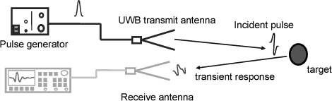
The method consists of recording the response of the system directly in the time domain (Figure 18.1). A generator of ultra short impulses without carrier feeds a UWB antenna, which transforms this impulse into an electromagnetic (EM) wave with an instantaneous spectrum contained between a few MHz and several GHz. This wave interacts with the system to be measured. Its response is then detected by a UWB antenna and observed by means of a digital oscilloscope. Then a simple Fourier transform allows us to deduce the transfer functions and the RCS directly on a wide frequency band. This technique avoids most of the major drawbacks because it enables us:
– to eliminate the parasitic fixed echoes (coupling between antennas and echoes of the infrastructure) whilst keeping the useful signals due to targets with a simple subtraction in the time domain between the signals measured with a target and those without a target;
– to use the “time windowing” to eliminate the multiple paths. The configuration of the system has to lead to a sufficient duration with the aim of measuring the useful signal without disturbance due to the multiple paths. This duration is called “clear time”. Points beyond this time window are cancelled during the numeric posttreatments;
– to authorize the test of systems with very large dimensions (outdoors);
– to lower considerably the floors of noise via an ‘averaged real-time’ acquisition allowing the outdoor experiment;
– a high speed of acquisition (all the frequencies in one shot).
Figure 18.1. Principle of the test bench of RCS UWB transient measurement
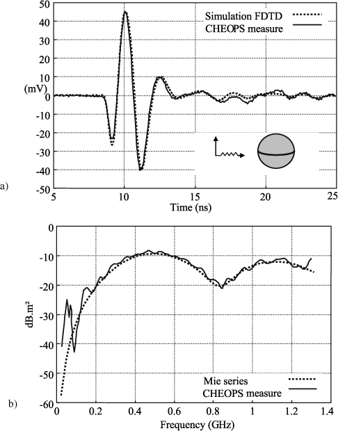
The measured transient response for a 200 mm sphere with the test bench developed by XLIM in the anechoic chambers of the CELAR [CHE 02], an establishment of the General Delegation for the Armament, shows a good agreement with the theoretical values obtained by the FDTD algorithm (Figure 18.2). The difference between RCS values obtained experimentally and theoretical values deducted from the Mie’s series are at most 2 dB for frequencies higher than 200 MHz.
Figure 18.2. a) Sphere of 200 mm — transient response; b) sphere of 200 mm — RCS
18.2.2. An impulse UWB radar with aperture synthesis: PULSAR
18.2.2.1. Problem of electromagnetic detection
Taking account of new threats on the military plan (terrorism, guerrilla warfare, urban fights), the considerable number of antipersonnel and antitank land mines spread on the surface of the earth and the numerous deficiencies in intervention and rescue during major natural disasters (tsunamis, earthquakes, cyclones, avalanches etc.) it became an absolute priority to conceive fast, precise tools of localization and reliability in identification.
The devices thus have to allow the detection of:
– buried targets (antipersonnel and antitank land mines, etc.);
– targets hidden in the vegetation or behind walls;
– intruders (for example in the crowd);
– dangerous materials (terrorism, etc.);
– furtive targets (vectors for strategic weapons);
– human presences and vital signs (avalanches, earthquakes, etc.).
Very precise identification requires an important quantity of information (on a large spectral domain) and a fine resolution of the radar image (inversely proportional to the bandwidth). The crossing of obstacles with various natures requires a spectrum with a big variety of frequencies enabling the wave to penetrate into openings of diverse sizes and a strong content into low frequency in order to favor the penetration of the wave through diverse screens (grounds, vegetation, walls, etc.).
Our team appears as one of the pioneers of the French scientific community in the development and the emergence of ultra-wideband pulse radar through the conception and through the realization of probationary means. The use of “without carrier” wave shape contrary to the other types of UWB radars (with step frequency modulation or with linear frequency modulation) presents numerous advantages:
– a higher discretion;
– a simpler system in terms of architecture (no demodulator, no correlator);
– a much shorter time of acquisition (nanoseconds against milliseconds);
– a better immunity;
– no complex post-treatment to isolate the useful responses.
18.2.2.2. PULSAR project
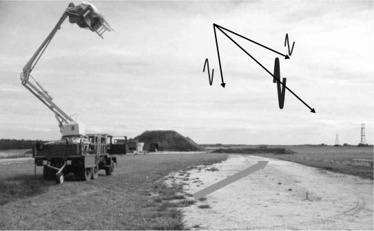
PULSAR project developed in association with the CELAR to conceive a GPR (ground penetrating radar) system dedicated to the detection of objects buried in the ground joins directly in these optics of research [GAL 02]. This operational means (Figure 18.3) allies the advantages of low frequencies (penetration in grounds, through walls and screens of vegetation) to those offered by the big bandwidth (strong resolution) and by the multitude of frequencies (robustness in the disturbances, fights against the stealth, improvement of the identification of targets). Its principle of functioning consists of illuminating by means of an ultra-brief impulse a scene associating mines on-surface or buried in the ground, to build an EM image allowing us to localize these objects.
This technique requires a side movement of the carrier of the system along the scene to be embellished with images to synthesize a unique antenna with strong gain.
Figure 18.3. PULSAR system (collaboration DGA/CELAR — XLIM)
The Figure 18.4 illustrates a measurement made with this radar demonstrator. Objects are detected from the visible hyperbolas on the map of measured impulse responses. The vertical strips observed on the map are due to the coupling between antennas and to the fixed echo due to the presence of the carrier. The elimination of the parasitic signals with a constant level during the movement of the radar is essential to highlight the relevant information relative to the echo of targets. A solution consists of subtracting from every impulse response an average signal determined by making the average of all the measured signals.
The SAR treatment (synthetic aperture radar) is based on the method of back-projection, which consists of compensating for the migration of the response of a target on a wide angle and in integrating the energy of the migration hyperbola in a point. The digital method consists of adding, in a coherent way, the impulse responses measured on the path corresponding to the movement of the radar in front of the scene. All the calculations are made in the time domain.
18.3. The ultra-wideband antennas
Antennas dedicated to the generation and the capture of ultra-short pulses have to respect the following criteria:
– 1st criterion: a working on a wide frequency band;
– 2nd criterion: no distortion of the radiated or receipt signal.
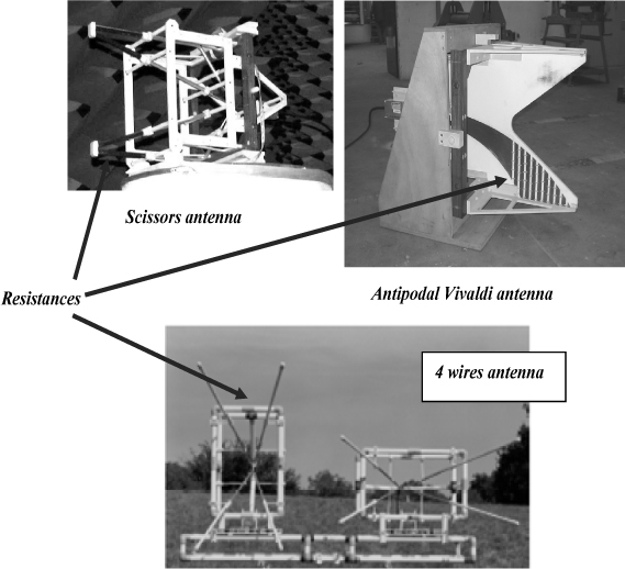
The majority of the resultant shapes imagined by XLIM follows from transmission lines intrinsically wideband, the geometries of which are flared [VAU 06]. These traveling wave antennas presenting a soft and progressive transition are 2D structures (for example the Valentine antenna and the Scissors antenna) adapted to the antenna arrays, or 3D structures (the 4 wires antenna, the Dragonfly antenna).
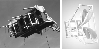
These antennas present a long working span (at least ten decades) and are directive. The constraints (cost, size, integration) are difficult because of the narrow dependence of the sizing of this type of antenna with the wavelengths to be managed. The antenna must be long enough so that the feeding currents are radiated before having reached their extremities, so eliminating any phenomenon of resonance. Figure 18.5 presents two antennas realized within the laboratory.
An antenna that is too short, towards a minimal frequency to be radiated or to be transmitted, does not allow us to radiate or to suitably measure the associated transient pulse. So, if the excitation feeding the antenna has a strong spectral content around this frequency, the phenomena of resonance in this part of the spectrum will be at the origin of:
– a spreading of the shape of the generated wave;
– a high level back radiation;
– a matching difficult to realize.
Figure 18.4. a) Map of the measured transient responses; b) associated EM image
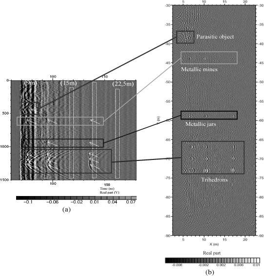
Figure 18.5. Dragonfly antenna (right) and Scissors antennas integrated on the PULSAR radar (left)
The value of the minimal frequency of the working band is directly linked to the length and to the opening of this type of antenna. The maximal frequency is linked to the electric and mechanical characteristics of the input of the antenna and consequently to its matching to the pulse source. The acquired experience during these last ten years demonstrated on a purely practical plan the existence of a compromise to be considered between the tension to be supported by the antenna, the duration of the signal to be generated, the input impedance and the bandwidth.
Figure 18.6. Calculation of the current in the input of a ULB antenna by EM simulation
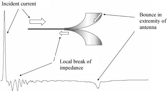
During the studies, two types of mismatches were distinguished (Figure 18.6):
– mismatches due to the geometrical profile and to the dimensions of the antenna;
– mismatches due to the discontinuities of impedance and mechanical discontinuities (connections) in the input of the antenna;
– mismatches due to the geometrical profile and to the dimensions of the antenna.
The reflected currents weaken as they move between the extremities of the antenna and the generator (Figure 18.7). This phenomenon of resonance is responsible not only for the appearance of parasitic additional pulses on the field radiated in the axis, but also contributes to degrade the standing waves ratio of the antenna. The distance separating the main impulse of the first parasitic bounce corresponds to twice the length of the wires, which is a return path of the reflected currents.
Figure 18.7. Display of the phenomena of resonances in the case of a 4 wire antenna (XLIM design)
Two solutions were recommended:
– increase the surface of the antenna and this to the detriment of the dimensions (see Figure 18.8);
– use loads (resistances) in the extremities of the structures to absorb the unradiated currents of excitation. This matching technique was used on several models of antennas within the laboratory (Figure 18.9);
There are mismatches due to the discontinuities of impedance and mechanics (connections) at the input of the antenna.
Figure 18.8. Valentine antennas (XLIM) a) of big width; b) narrow
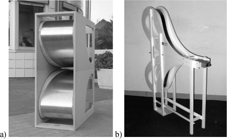
Figure 18.9. UWB antennas (XLIM) with matching resistances
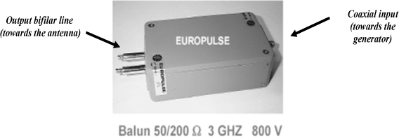
Mostly, UWB antennas are fed via a coaxial interface (towards the generator). For applications requiring the radiation and the measure of signals without important distortion as well as radiation pattern with symmetric lobes, the antennas with differential supply conceived by the team required the use of “baluns” (Figure 18.10).
These devices whose name is due to the contraction “balanced — unbalanced” realize the matching of the previous 2 wire structures to the pulse sources and to the oscilloscopes. They allow the following functions:
– the balance of the signals on each wire in time and in magnitude;
– the geometrical transformation between the coaxial structure of the cable and the structure of the input line, for example bi-wire type for the Scissors antenna and 4 wire antenna and of bi-strips type for the Valentine and Dragonfly antennas (Figures 18.5 and 18.8);
– the impedance matching if it is necessary, for example 200 Ω for Scissors and 4 wires antennas.
The balun is able to work on a wide frequency band and to not distort the pulses but also to support the high voltages applied to antennas for radar applications. The level of 30 kV constituted the limit for a signal with a half-time duration of about 1 ns.
Figure 18.10. Balun 50 Ω, 200 Ω, 1 kV, 300 MHz — 3 GHz; EUROPULSE-France
18.4. Limitations of a mono-source device: implementation of multi-source devices with optoelectronic excitation
18.4.1. RUGBI project
The solution of the association of several elements in emission, each consisted of a source delivering pulses lower than 20 kV (100 ps rise time, 500 ps duration) and an UWB antenna, appeared as the ideal solution to by-pass the hard points due to the high-voltage ability of an elementary antenna in this frequency band. So the RUGBI project [LAL 09] enabled us to easily realize a complete system of four Valentine antennas fed by 10 kV, with performances equivalent to those of a “hypothetical” mono-source system fed by 40 kV of very difficult implementation (Figure 18.11).
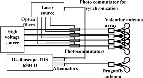
The conception of this probationary means (Figure 18.12) relies on concept multi-sources with optoelectronic excitation to accumulate the energy radiated by every elementary element in a given direction. The supply by laser flash allows us to perfectly control the synchronization of each source (jitter of the order of the picosecond) and so to synthesize a single source of strong level.
Figure 18.11. Array of 4 UWB Valentine antennas (RUGBI project)
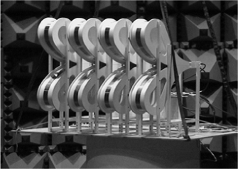
Figure 18.12. Overview diagram of the RUGBI UWB radar with optoelectronic excitation
Results for validation of the concept multi-sources implemented in the project RUGBI are presented below:
– Validation of the concept of the accumulation of radiated energy in the axis.
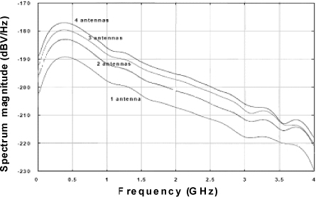
Figure 18.13 presents the transient signals measured at the feet of a UWB antenna positioned in front of a Valentine antennas array. The level of the received field is equal to the product obtained with a single antenna by the number of antennas placed in emission. We note that the rise time is preserved in ± 5% and the width of the pulse in ± 1%. The Figure 18.14 presents the Fourier transform of the previous transient signals. An increase of the amplitude of 6 dB is noticed when the number of antennas is doubled.
Figure 18.13. Transient signals measured in the axis
Figure 18.14. Fourier transform of the measured transient signals
– Validation of the concept of beam steering without distortion of the signal shape.
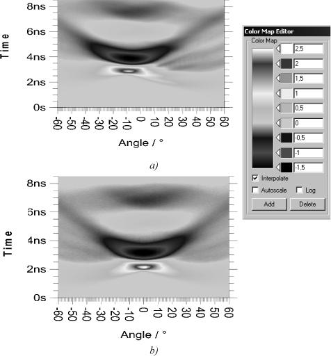
The graph which represents the transient electric field as a function of time and angle is a suitable UWB radiation source descriptor. Figure 18.15 represents this type of characteristic for two cases: a) the four antennas are excited with time delays corresponding to 10° beam steering; b) the four antennas are excited simultaneously. The transient and spatial radiation patterns observed with the beam steering of 10° are identical to those observed without beam steering. On the other hand, parasitic array lobes appear on the opposite site to the steering.
Figure 18.15. Transient radiation patterns a) beam steering 10°; b) beam steering 0°
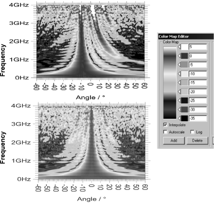
In Figure 18.16, the harmonic radiation pattern corresponding to the representation of the amplitude function of the frequency and the angle of observation are presented. In the case of beam steering (10°), the main lobe is identical in terms of shape to that obtained without steering. The orientation of the beam does not vary with the frequency. This network is not dispersive. Parasitic array lobes exist over 1 GHz. These lobes have a higher level than that of the main lobe from 2.5 GHz.
Figure 18.16. Harmonic radiation patterns with beam steering (10°) and without beam steering
18.4.2. Last evolutions around multisource systems
It clearly seemed that the realization of operational optoelectronic radar passed by the miniaturization of the elementary antenna to be able to increase, with the increase of the number of antennas, the accumulated power and thus the impact of the systems. For that, a UWB array was imagined (Figure 18.18) constituted by 12 UWB miniature antennas (lower maximal dimensions in λ/4) covering an operation band (300 MHz – 3 GHz) [GOD 07]. A system of corrugations around the antenna array allowing us to strongly improve the front-to-back ratio (35 dB). In parallel with the phase of design of the array, a phase of design of optoelectronic sources delivering “monocycle” type pulses was conducted within the laboratory. The generated signals were so adapted to the electrical behavior of antennas and thus the problems of coupling between emission modules and the reception module are limited. Therefore, the sensibility of the means and thus the impact are strongly increased. A confrontation theory-experiment is proposed in Figure 18.17. This is about the radiation pattern of the UWB antenna array observed following the vertical plane of the system for controlled steering (adjustment of the optical delays on every source) of 12°.
Figure 18.17. Radiation pattern (at f = 2 GHz) with beam steering (12°) in the horizontal plane of the array
Figure 18.18. UWB multisource system (300 MHz – 3 GHz)
18.5. Pulse antenna systems in high power microwaves
For offensive electronic war, the capacity to emit pulse parasites on very widebands in the ranges of frequencies where equipments are vulnerable is a main advantage. Furthermore, if the directivity of the emission with regard to the target is optimized, the transmit levels are stronger, the fratricide effects are less important and the time of interaction is faster. Consequently, the agility of the system is an important advantage.
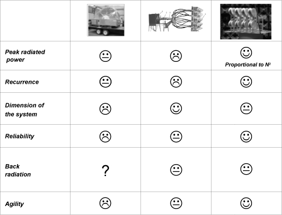
At present, three types of pulse radiation system architecture can be listed. Figure 18.19 specifies these various approaches, the American system (JOLT) which associates 1 source and 1 HIRA’s type antenna [BAU 04], the Russian system (HCEI) which associates 1 source and 16 antennas of type K [KOS 04], thus requires the use of a power divider, and the RUGBI detection system which associates N sources and N antennas. By controlling the delays of every module, only the last two systems are able to offer some agility in terms of angular steering.
Figure 18.19. The different architectures of HPM (high power microwaves) radiating systems
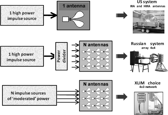
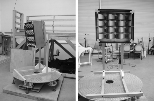
Table 18.1 underlines the performances of every probationary means with particular evolution of the system RUGBI envisaged for the high power integrating 62 Valentine-type antennas. The major interests of this last architecture are:
– the radiated peak power is proportional to N2 (N: number of antennas in the array);
– the continuity of operation of the device during the failure or during the stop of one or several pulse sources;
– the control of the generated wave shape and of the beam steering.
Table 18.2 specifies advantages and defects of every type of architecture.
Table 18.1. Summary of the performances of HPM radiation systems
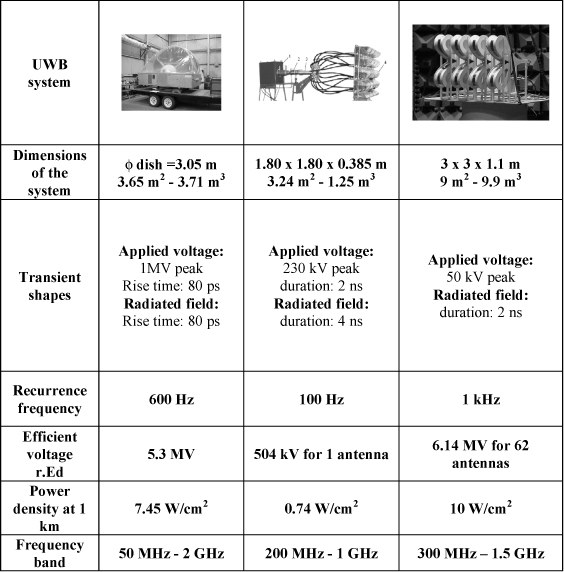
Table 18.2. Advantages and defects of every type of architecture
XLIM has elaborated an elementary optoelectronic source of an agile array, able to answer the requirements of the HPM problem. Two major technical points have been resolved during this project:
– One concerns the optoelectronic switching, where was demonstrated the capacity to generate a monocycle electric pulse controllable in terms of transient shape on a spectrum from 800 MHz to 8 GHz, while guaranteeing peak to peak levels of some kV on every module.
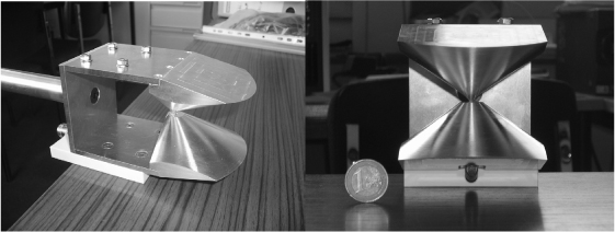
– The other one concerns the conception of an antenna and its feed system, the dimensions of which are low compared to the most important working wavelengths (see Figure 18.20) [DES 09].
In a near future the control of this module will enable the proposal of a complete system the performances of which will only be due to the element number in the array and to the available optical power. Densities of power of the order of 1 W/cm2 are possible with a range of 1 km.
Figure 18.20. SHARK antenna, elementary module of a HPM-UWB antenna system (800 MHz – 8 GHz)
18.6. Conclusion
In recent years, XLIM undertook extensive research into the conception and the realization of probationary ultra-wideband means. These means which deliver high power radiated waves, with a rise time of the order of hundreds of picoseconds and with duration of some nanoseconds cover frequency bands greater than a decade. These transient shapes are perfectly adapted to the current problems of electromagnetic detection and the electronic warfare. Currently, three types of pulse system architecture can be listed:
– the mono-source systems;
– the multisource systems 1 generator-N antennas;
– the multisource systems N generators-N antennas.
XLIM favors the last concept by conceiving UWB antenna array fed by optoelectronic sources controlled by laser flash. This approach presents several essential advantages in comparison with a mono-source situation due to the continuity of equipment operation during the failure or during the stop of one or several pulse sources, the radiated peak power proportional to N2 and the agility in terms of wave shape and angular steering. Various demonstrators integrating miniature antennas to guarantee the operational aspect were conceived:
– an agile array for detection with an optoelectronic feed, in the band 300 MHz – 3 GHz;
– a high power microwave agile array with an optoelectronic feed, in the band 800 MHz – 8 GHz.
18.7. Bibliography
[BAU 04] BAUM C.E., BAKER W.L., PRATHER W.D., LEHR J.M., O’LOUGHLIN J.P., GIRI D.V., SMITH I.D., ALTES R., FOCKLER J., MCLEMORE D., ABDALLA M.D., SKIPPER M.C., “JOLT: a highly directive, very intensive, impulse-like radiator”, Proceedings of the IEEE , vol. 92, no. 7, July 2004.
[CHE 99] CHEVALIER Y., IMBS Y., BEILLARD B., ANDRIEU J., JOUVET M., JECKO B., LE GOFF M., LEGROS E., “UWB measurements of canonical targets and RCS determination”, in E. HEYMAN , B. MANDELBAUM and J. SHILOH , KLUWER (eds) Ultra-Wide band, Short-Pulse Electromagnetics , vol. 4, Academic/Plenum Publishers, New-York, USA, pp. 329–334, 1999.
[DES 09] DESRUMAUX L., LALANDE M., BERTRAND V., ANDRIEU J., COUDERC V., BRUGUIERE P., “Source de puissance rayonnée impulsionnelle optoélectronique”, Rencontre DGA — Recherche et Innovation Scientifique, Paris, 14 May 2009.
[GAL 02] GALLAIS F., ANDRIEU J., BEILLARD B., IMBS Y., MALLEPEYRE V., JECKO B., LE GOFF M., “A new ultra wideband, short pulse, radar system for mine detection”, in P.D. SMITH AND S.R. CLOUDE (eds), Ultra-Wideband Short-Pulse Electromagnetics , Volume 5, Kluwer Academic/Plenium Publishers, New York, USA, pp. 175–182, 2002.
[GOD 07] GODARD A., VAUCHAMP S., BERTRAND V., ANDRIEU J., LALANDE M., JECKO B., “On UWB transient generation system architectures: consequences on antenna design”, EuCAP2007, 2nd European Conference on Antennas and Propagation , Edinburgh, UK, 11–16 November 2007.
[IMM 02] IMMOREV I.I., TAYLOR J.D., “Optimal short pulse ultra-wideband radar signal detection”, in SMITH AND CLOUDE (eds), Ultra-Wideband Short-Pulse Electromagnetics, Volume 5, Kluwer Academic/Plenium Publishers, New-York, USA, pp. 207–214, 2002.
[KOS 04] KOSHELEV V.I., GUBANOV V.P., EFREMOV A.M., KOROVIN S.D., KOVALCHUK B.M., PLISKO V.V., STEPCHENKO A.S., SUKHUSHIN K.N., “High-power ultra-wideband radiation source with multielement array antenna”, 13th International Symposium on High Current Electronics , 2004.
[LAL 09] LALANDE M., DIOT J.C., VAUCHAMP S., ANDRIEU J., BERTRAND V., BEILLARD B., VERGNE B., COUDERC V., BARTHELEMY A., GONTIER D., GUILLEREY R., BRISHOUAL M., “An ultra wideband impulse optoelectronic radar: RUGBI”, PIER B , vol. 11, pp. 205–222, 2009.
[VAU 06] VAUCHAMP S., DIOT J.C., LALANDE M., JOUVET M., ANDRIEU J. BERTRAND V., VERGNE B., COUDERC V., JECKO B., “Antennes agiles optoélectroniques impulsionnelles : principes et applications”, Revue de l’électricité et de l’électronique , REE no. 1, pp. 73–83, January 2006.
1 Chapter written by Joël ANDRIEU and Michéle LALANDE.