
Chapter 3
Space-time Exploration for Airborne Radars1
3.1. Introduction
Long range airborne surveillance is a very demanding application for radar designers, and now generally requires active antennas (multiple transmitters), improved power budget, increased availability and beam agility and adaptivity. Fixed targets are detected with high resolution SAR, requiring instantaneous bandwidths ranging from 500 MHz to 1 GHz, and moving air and ground targets are detected with MTI modes using space-time adaptive processing (STAP) for clutter rejection – which requires multiple channels on receive. This means that modern airborne radars generally implement multiple channels and wideband transmit/receive radio-frequency front-ends.
Taking that specificity into account, we must determine the best waveform and scanning strategy for a specific surveillance mission, taking into account the very limited time available for surveillance of wide areas at long range.
The purpose of this chapter is to outline the main possibilities and to show that the simultaneous requirement for wideband and multiple channels opens the way to new beamforming techniques and waveforms, where different colored signals are simultaneously transmitted for coding space and time, and coherently processed in parallel on receive. Such concepts, first proposed and demonstrated by S. Drabowitch [DRA 68] and J. Dorey [DOR 78], should now be considered as mature techniques to be implemented on operational systems.
This chapter, essentially tutorial in nature, is based on a survey paper published by the Chinese journal Radar Science and Technology [LEC 08]. In the following, we will successively consider colored space-time exploration (section 3.2), interleaved scanning (section 3.3), and wideband moving target indication (section 3.4). The conclusion will emphasize the benefits of optimized space-time management on transmit and receive, for surveillance MTI modes.
3.2. Colored space-time exploration
3.2.1. Digital beamforming (DBF)
Standard digital beamforming is a procedure where wide angular sector instantaneous coverage is obtained with a wide beam illumination on transmit (transmission through one sub-array), and directive beams are formed on receive through coherent summations of signals received on different sub-arrays, in parallel for each direction.
Digital beamforming generally does not essentially change the power budget, compared to standard focused exploration, since the lower gain on transmit (due to wider illumination) is traded against a longer integration time (made possible by the simultaneous observation of different directions).
Digital beamforming may provide specific advantages, such as a better visibility of short events (e.g. rcs flashes), and a higher Doppler resolution especially useful for identification purposes, or for detection of slow targets.
However, for airborne applications, a severe limitation arises from the clutter spreading in Doppler, due to the wider beam on transmit (which is, anyway, difficult to obtain with active antennas): this leads to a poor minimum detectable velocity, and to a poor clutter rejection, since only half the dBs are obtained, compared to focused beam illumination. This is the main motivation for turning to colored transmission.
3.2.2. Colored transmission
3.2.2.1. Principles
The principle of colored transmission consists of simultaneously transmitting different waveforms in different directions, thus achieving space-time coding; see Figure 3.1. In this figure, the coding is assumed to be a succession of sub-pulses, coded in phase or frequency, but any type of code can be used [LEV 04] – for instance, transmitting different frequencies through the different sub-arrays could also be a possibility. The directivity on transmit is then recovered by signal processing on receive.
Figure 3.1. Colored transmission
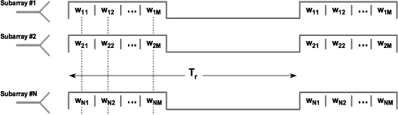
For signal processing on receive, the transmitted waveforms should be orthogonal, so that they can be separated from one another, on each receiving channel.
It should be emphasized that the transmitted waveforms are still periodic, since that is a necessary condition for an efficient cancellation of long range clutter (e.g. mountains).
Figure 3.2. Successive diagrams a) frequency coding; b) fast angular scanning; c) pseudo-random orthogonal diagrams
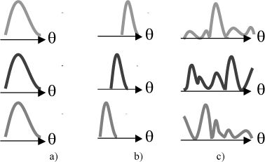
Another way to consider such concepts is to describe them as the transmission, during each subpulse number i, through successive diagrams, the ith diagram Di(θ) resulting from the illumination law w1i, w2i, … wNi on the array, as illustrated in Figure 3.2 for three different concepts: frequency coding (identical diagrams at different carrier frequencies), fast angular scanning and pseudo-random orthogonal diagrams.
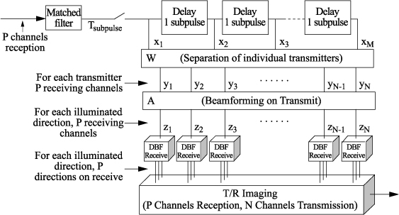
The optimum processing then basically consists of the operations described in Figure 3.3 (essentially a coherent summation of the received samples, for each angle – Doppler – range hypothesis):
– Transverse filtering, for separating the signals received from the different transmitters.
– Digital beamforming on transmit (basically Fourier transform), coherently summing the transmitted signals, for each receiving antenna (i.e. each receiving channel).
– Digital beamforming on receive (again basically Fourier transform).
Figure 3.3. Optimum reception of colored signals
For increased performances in cluttered environments or adverse conditions, digital beamforming will preferably be performed with appropriate adaptive algorithms [LEC 02], on transmit and receive.
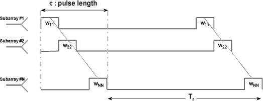
3.2.2.2. Circulating pulse
A simple example is illustrated in Figure 3.4: the “circulating pulse”, where a sub-pulse is successively transmitted through each sub-array: wkl = δ(k - l). If the sub-arrays are regularly spaced (uniform linear array) horizontally, this is equivalent to moving the phase center very rapidly through the whole array, thus creating an artificial Doppler (SAR effect) on transmit. For example, if the sub-pulse is 100 ns long, with 10 sub-arrays, this produces an artificial Doppler of ± 5 MHz (clearly distinct from the standard Doppler effect, which can only be measured as a phase shift from pulse to pulse).
Figure 3.4. Circulating pulse
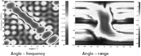
The global effect is equivalent to a frequency coding in azimuth, which is shown in Figure 3.5, where each column represents the spectrum of the transmitted signal, evaluated through a Fourier transform for a duration equal to 1 μs (providing approximately 1 MHz resolution).
Figure 3.5. Circulating pulse: angle-frequency coding (sub-pulse: 100 ns long, with 10 sub-arrays on transmit)
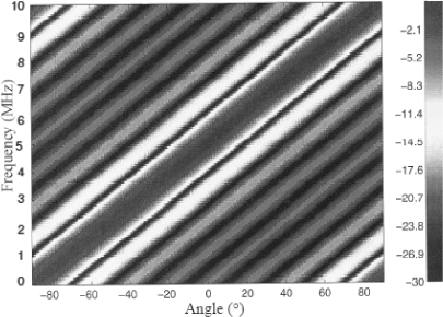
This representation of the space-time waveform will be an efficient tool for code optimization in the next section. It is the bidimensional Fourier transform of the matrix W=[Wnm], each line (function of sin(θ)) being the diagram at the radiated frequency f.
Referring to Figure 3.2 (space-time coding as a succession of diagrams), this coding is similar to type a): the diagram is identical from sub-pulse to sub-pulse, but the phase center of the antenna changes (rather than the frequency, as assumed in Figure 3.2).
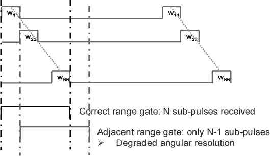
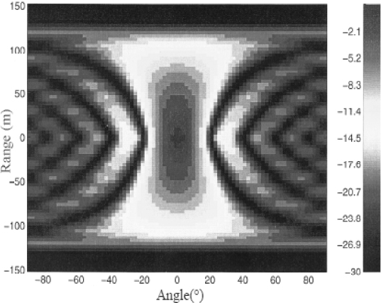
In this example, it can be seen that the standard radar ambiguity is now a range-angle-Doppler ambiguity, since the coding is indeed a space-time coding. This effect is illustrated in Figure 3.6 and more specifically, the coupling between range and angle. Whereas the matched filtering correctly sums all the returns from a given target, in the adjacent range gate (separated by 100 μs, corresponding to the total 10 MHz bandwidth, in our example), only N-1 returns are summed, with a reduced effective antenna (by a factor (N-1) / N) providing a reduced angular resolution from the same factor.
Figure 3.6. Circulating pulse: range-angle ambiguity
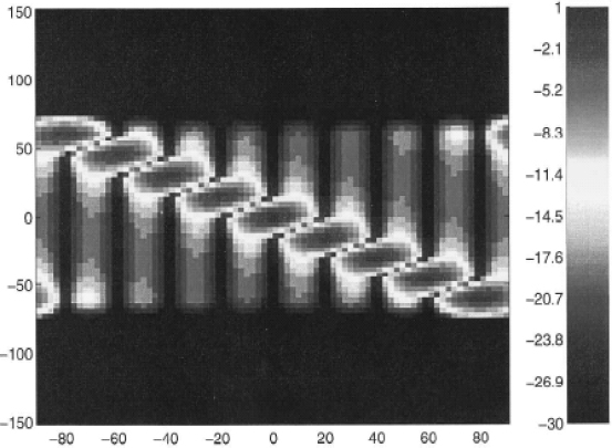
This range-angle ambiguity function is shown in Figure 3.7, for the same example: the widening of the peak in angle, in adjacent ranges, is clearly visible.
The essential limitation of this simple space-time coding is the fact that only one transmitter is operated at each instant: it is generally preferable to use all the transmitters simultaneously, so as to maximize the effective radiated power (although that depends on the precise characteristics of the active elements, such as the maximum tolerable duty factor). The circulating code, presented below, will alleviate this limitation.
Figure 3.7. Circulating pulse: range-angle ambiguity (sub-pulse: 100 ns long, with 10 sub-arrays on transmit and only one on receive)
3.2.2.3. Fast scanning (intra-pulse scanning)
In this mode, the angular diagram is rapidly scanned, from sub-pulse to sub-pulse, as described in Figure 3.2b, ![]() . There is a total ambiguity between time (range) and angle, as shown in Figure 3.8, which can be removed, for example, by symmetrically scanning in the opposite direction, or by changing the frequency from sub-pulse to sub-pulse.
. There is a total ambiguity between time (range) and angle, as shown in Figure 3.8, which can be removed, for example, by symmetrically scanning in the opposite direction, or by changing the frequency from sub-pulse to sub-pulse.
Figure 3.8. Intra-pulse scanning: range-angle ambiguity (sub-pulse: 100 ns long, with 10 sub-arrays on transmit and only one on receive)
The main advantage of this waveform is that the beamforming is performed electronically, thus reducing the computing load compared to the other solutions.
3.2.2.4. Circulating chirp
A more interesting example is given in Figure 3.9, where the coding is a “circulating chirp”: ![]() , with 10 sub-arrays and 10 sub-pulses, 100 ns each, and one sub-array on receive: the operation is equivalent to a frequency-azimut coding (one frequency in each direction). Compared to standard DBF, such colored transmission schemes effectively provide angular separation on transmit, at the price of an increased instantaneous frequency bandwidth: higher Doppler resolution is now possible, without clutter spreading.
, with 10 sub-arrays and 10 sub-pulses, 100 ns each, and one sub-array on receive: the operation is equivalent to a frequency-azimut coding (one frequency in each direction). Compared to standard DBF, such colored transmission schemes effectively provide angular separation on transmit, at the price of an increased instantaneous frequency bandwidth: higher Doppler resolution is now possible, without clutter spreading.
Compared to the circulating pulse, the properties are similar, but all the available transmitters are now used simultaneously.
Figure 3.9. Circulating chirp
3.2.2.5. Bidimensional frequency coding
Another example for fighter radars is illustrated in Figures 3.9 and 3.10, where a bidimensional angular coding is implemented. The array is made up of about 1,000 elementary antennas (possibly grouped under sub-arrays arrangement), and the pattern of transmission shown in Figure 3.10 (3 columns transmitting frequency f1 with elevation θ1, 3 adjacent columns transmitting frequency f2 with elevation θ2, and again 3 adjacent columns transmitting frequency f3 with elevation θ3), is rapidly scanned horizontally through the array, thus realizing an azimuth coding through a circulating code technique similar to those described previously.
Figure 3.10. Bidimensional coding
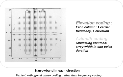
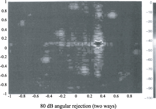
Globally, this is equivalent to an elevation/azimuth frequency coding, providing on receive the diagram shown in Figure 3.11 for a specific angular steering direction: the sidelobe level is in the order of 80 dB (two ways), thus allowing medium- or high-repetition frequency modes to be implemented for air-air detection and tracking over the global angular coverage. The overall extent of the angular sector can be adapted by suitable arrangements of the columns selected for transmission, taking into account the existing sub-arrays.
Figure 3.11. Bidimensional coding diagram
3.2.2.6. Target coherence and diversity gains
Until now, the target was supposed to be an isotropic (in aspect angle) white (in frequency) scatterer, so that the received signals could be coherently added on reception. In reality, the target may more accurately be represented as a distribution of isotropic white scatterers, characterized by their position ![]() relative to a specific point on the target, and by their complex diffraction coefficient I (
relative to a specific point on the target, and by their complex diffraction coefficient I (![]() ).
).
This specific nature of the target has consequences on the performance of the radar system, since it changes the result of the coherent summation, and consequently the accuracy of the measurements. We will briefly summarize and illustrate the main results in the following.
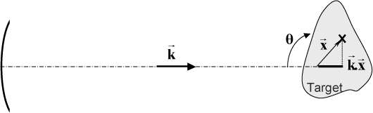
Within this model, the scattering coefficient of the target, H (![]() ), can be written as a function of
), can be written as a function of ![]() , the wave vector (vector along the incidence angle, modulus
, the wave vector (vector along the incidence angle, modulus ![]() ), as described in Figure 3.12:
), as described in Figure 3.12:
![]()
Since this expression is a Fourier transform, it can be inverted to provide the image I (![]() ) of the target (to within a scalar coefficient, obtained through calibration), based on the available measurements H(
) of the target (to within a scalar coefficient, obtained through calibration), based on the available measurements H(![]() ):
):
![]()
the limits of the integral being determined by the measurement system (usually a frequency bandwidth Δf centered on f0, and an angular sector Δθcentered on θ0).
Figure 3.12. Target scattering coefficient
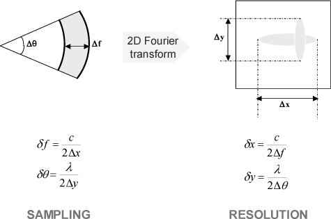
This is the basis of holographic measurements [POU 78, LEC 02], routinely used for target analysis. It also provides the basic parameters for sampling in the ![]() domain, and for resolution in the
domain, and for resolution in the ![]() domain, when observing a target with depth Δx and transverse dimension Δy, with an observation bandwidth Δf on an angular sector Δθ, as described in Figure 3.13 (these relations are mere consequences of the Fourier transform relationship between the measurement hologram H(
domain, when observing a target with depth Δx and transverse dimension Δy, with an observation bandwidth Δf on an angular sector Δθ, as described in Figure 3.13 (these relations are mere consequences of the Fourier transform relationship between the measurement hologram H(![]() ) and the target image I(
) and the target image I(![]() )).
)).
Figure 3.13. Sampling and resolution criteria
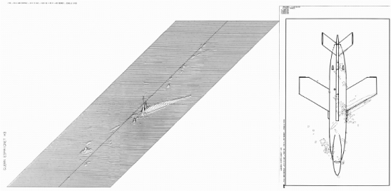
The image obtained on a real target drone (CT20) is presented in Figure 3.14, for an observation in the horizontal plane, with an angular sector width of 20° centered on 40° and a frequency bandwidth of 2 GHz centered on 9 GHz.
Figure 3.14. Example of a real target (drone CT 20) image (courtesy of ONERA)
These basic analysis tools provide essential parameters for target coherence: the critical instantaneous bandwidth and the critical antenna array extent.
The critical bandwidth Δfc is defined as the maximum bandwidth while the target coefficient remains coherent:
![]()
In other words, if the bandwidth transmitted in the direction of the target is equal or larger than Δfc, then the received signals cannot be coherently summed – the target is resolved in range by the signal. For instance, if the maximum dimension of the target is Δx = 30 m then Δfc = 5 MHz.
As a consequence, when the bandwidth transmitted in the direction of the target is equal to or larger than Δfc, the targets being resolved in range, some kind of distributed target integration has to be implemented, thus providing a diversity gain on fluctuating targets.
Similarly, as shown in Figure 3.15, the critical array extent Dc is the maximum extent of the antenna array such that the target coefficient, observed at range R, remains coherent:
![]()
Figure 3.15. Critical array extent Dc
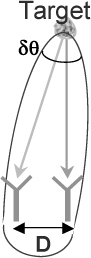
If the extent of the array is larger than Dc, then the system cannot be considered to be a monostatic system, and the received signals cannot be coherently summed: in other words, the target is resolved in angle by the array (which again can provide some kind of diversity gain when correctly processed). For instance, if R = 100 km, Δy = 30 m and λ = 3 cm we obtain Dc = 50 m: this means that very generally, for monostatic systems, the extent of the antenna array is much smaller than the critical extent, and only bistatic systems can be used for resolving the target in angle.
These two critical parameters Δfc and Dc should be considered basic parameters in the design of so-called MIMO systems, as was also correctly analyzed by V. Chernyak [CHE 07] and Y. Peng et al. [WUY 06] (the “full rank observation matrix” being equivalent to using an inter-element spacing larger than Dc).
Coming back to the previous examples, it may be noted that the circulating pulse and the circulating chirp transmit only narrow band signals in each direction (these techniques are basically angle-frequency codings), whereas in the intra-pulse scanning technique a wideband signal (sub-pulse) is transmitted in each direction.
3.3.2.7. Colored transmission trade-offs and applications
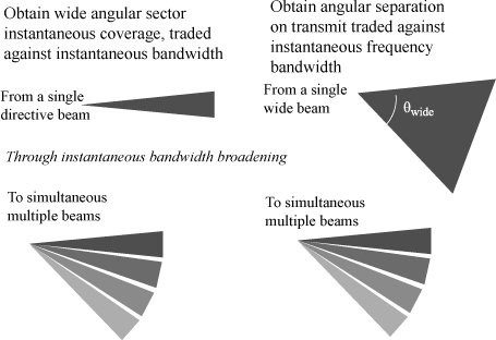
On the whole, as shown in Figure 3.16, these colored transmission techniques can be described as providing angular instantaneous coverage (wide angular sector), traded against a larger instantaneous frequency bandwidth. Or they can be described, starting from standard digital beamforming as providing angular separation on transmit (hence better clutter rejection), traded against instantaneous frequency bandwidth.
Such techniques could be used for instance for air-air combat mode, where they can provide the instantaneous wide coverage which is necessary while still maintaining a high visibility in clutter. Their strong resistance to jamming must also be emphasized, since any repeating jammer will give its position by repeating the received code, thus making it easy for the radar system to identify sidelobe jamming as such, and cancel the corresponding false plots.
These colored transmission techniques are also the solution to the standard “beams rendezvous” problem for bistatic systems: enabling a wide beam on transmit without incurring the widening of the main beam clutter spectrum (since transmission directivity is recovered on receive), they provide the well-known benefits of bistatic systems (namely an improved detection in clutter through decreased clutter ambiguities, covertness, and ECCM).
Figure 3.16. Colored transmission trade-offs
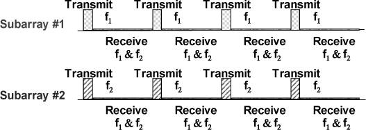
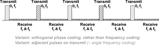
For surveillance radars, they also provide the solution to a classic dilemma: how to increase the Doppler resolution, needed for slow-target detection and target classification, without widening the clutter spectrum? This requires a wide beam, but also a fine angular resolution on transmit and receive. One possibility – actually very similar to the RIAS concept [DOR 78] – is illustrated in Figure 3.17, where each sub-array transmits a different frequency carrier, coherently summed on receive as explained above. Depending on the specific system generation and reception constraints, it might be preferable to transmit different orthogonal codes (frequency modulations, phase codes, etc.), rather than different frequency carriers.
Figure 3.17. Colored transmission for surveillance
It must be emphasized that in this case, each target is illuminated by the whole bandwidth, thus making it possible to use such modes for high range resolution analysis of the detected targets, or wideband MTI, as described in section 3.4.
3.3. Interleaved scanning
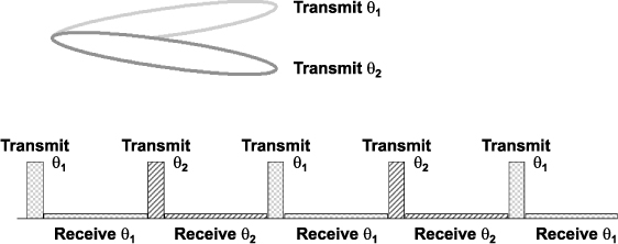
Another way to explore space is obtained by interleaved scanning, where successive pulses are sent in successive directions, thus interleaving different pulse trains – possibly with different frequencies, or different codes. An example is shown Figure 3.18, with 2 interleaved directions.
Figure 3.18. Interleaved scanning
This scheme enables us to trade a wider quasi-instantaneous coverage – with the possibility of implementing adaptive angular processing, by coherently processing the signals received from the adjacent beams – against a lower repetition frequency (and consequently more Doppler ambiguities) in each direction, and associated eclipses. This has no significant impact on the power budget: as for the previous colored emission concepts, the loss in overall gain on transmit is balanced by a longer integration time on the target.
With that interleaved scanning concept, it becomes possible to implement any adaptive procedure on receive, with only one channel on receive, if the transmitted signals are identical (so that the samples received from the different direction can be coherently processed to extract angle information). Of course however, we have to take into account the fact that the samples are not taken simultaneously, so Doppler information has to be incorporated into the spatial filter. More specifically, the standard adaptive angular filter W, to be applied to the vector z of collected samples in one range gate, which is classically written [LEC 02]:
now becomes a Doppler-angle filter:
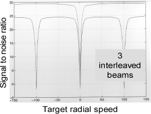
Such modes have been shown [LEC 99] to be an effective way of implementing STAP (space-time adaptive processing) with only one channel on receive: this is illustrated in Figure 3.19, with 3 interleaved directions. The result is of course an increased ambiguity in Doppler, and a loss of 5 dB in signal-to-noise ratio (due to the apparent widening of the beam), but a performance comparable to the 3 channels standard technique for slow target detection.
Figure 3.19. Interleaved scanning STAP
This mode, as shown in Figure 3.20, is also a possible solution to the bistatic “beams rendezvous” issue previously mentioned, enabling us to enjoy the benefits of multistatic systems without increasing the complexity of the synthesis/distribution parts, at the price of a reduced repetition frequency in each direction. Basically, that opens the way to multistatic search and track modes for low cost fighter radars, with effectively medium repetition frequency in each direction.
Such modes could also provide efficient solutions for long range air-ground or air-air surveillance systems, preferably with adjacent rather than evenly distributed pulses – which amounts to trading the Doppler ambiguities against increased blind zones at short ranges.
Figure 3.20. Interleaved scanning surveillance
This also comes back to the intra-pulse scanning described in section 3.2.2.3: interleaved scanning is a slow-time variant of space-time waveforms
3.4. Wideband GMTI [LEC 02]
An essential limitation for standard radars comes from a pulsed radar range-Doppler ambiguity relation, which states that the ambiguous speed Va and the ambiguous range Da are related by: Da x Va = λ × c / 4. That relation means that many ambiguities, either in range or speed (or both), have to be dealt with, which in turn implies the transmission of successive pulse trains with different repetition frequencies, requiring more time to be spent on target for ambiguity and blind speed removal.
An alternative solution is obtained by increasing the range resolution (or the instantaneous bandwidth), so that the moving target range variation (range-walk) during the pulse train becomes non-negligible compared with the range resolution: which is equivalent to stating that the Doppler effect is varying across the whole bandwidth (compared with the Doppler resolution), and can no longer be considered as a mere frequency shift. Such radars may use bursts with low pulse repetition frequency (no range ambiguities) wideband pulses such that the range-walk phenomena during the whole burst are significant enough to remove the velocity ambiguity. It then becomes possible to detect the target and to measure range and speed with only one coherent pulse burst.
The condition is written, if Nt is the number of pulses in the burst, Tr is the repetition period, Va is the standard ambiguity speed [Va = λ/(2Tr) ], ΔF is the instantaneous bandwidth,and δR is the range resolution [δR = c/(2ΔF)]:
For example, a burst of 60 pulses at 1 kHz repetition frequency with 500 MHz bandwidth would be a possible candidate for non-ambiguous MTI detection at the X-band.
The coherent signal processing of such radars (whose range resolution is in the order of a few wavelengths) involves (Figure 3.21), for each velocity hypothesis, a coherent summation of the received echoes (Fourier transform), after range-walk compensation:
This processing leads to an ambiguity function (Figure 3.21) which does not exhibit the periodic ambiguities in Doppler, and provides the following advantages:
– Simultaneous detection of fixed and moving targets (SAR+GMTI), with the high resolution low PRF pulse train appropriate for SAR imaging.
– High resolution range-Doppler classification: Figure 3.22 illustrates this possibility with the image of a hovering helicopter, with 50 cm resolution, where the main rotor and the tail rotor are clearly visible at ranges of 5 m and 13 m (signals obtained by electromagnetic modeling of a Puma helicopter).
– ECCM properties (spread spectrum signals, requiring specific interception for ELINT or ESM, and specific devices for simulation of the wideband Doppler compression effect).
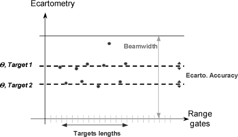
– Monopulse angular resolution of extended targets (essential for air-ground high target density situations), as shown in Figure 3.23.
Figure 3.21. Wideband signal processing and ambiguity functions: a) narrowband, 1/1,0000 bandwidth; b) wideband, 1/10 bandwidth
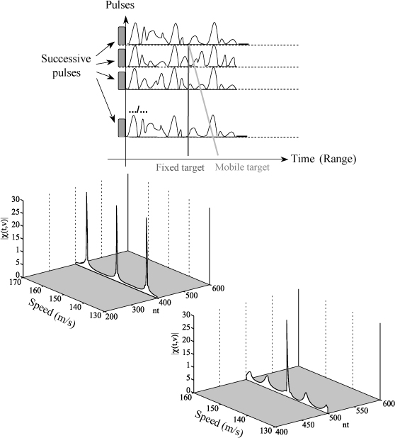
Figure 3.22. Helicopter HRR signature
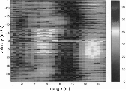
Figure 3.23. Wideband ecartometry
The processing of such wideband modes can be further improved for target extraction from clutter [DEU 10], thus providing efficient air-air modes with classification “on-the-fly”.
3.5. Conclusion
The different techniques briefly presented may be combined for simultaneous optimization of space exploration and target analysis and detection. For example, multi-frequency transmission through different sub-arrays, or circulating chirp coding, with a total instantaneous bandwidth between 500 MHz and 1 GHz, or interleaved multi-frequency pulse trains, will allow beamforming on transmit and receive and high resolution in range and Doppler, thus providing better detection, location, and classification of multiple ground and low-flying targets.
More generally, it may be interesting to note that, while the second half of the 20th century has seen major developments in radar waveform design and “time/Doppler” signal processing, this first decade of the 21st century is now focused on antenna developments around phased array design and “space/time” processing, on transmit and receive.
Cost reduction of active electronic scanning arrays and wideband integrated front-ends will enable generalization of these technologies for more demanding applications, and intelligent radar management will be required to take full advantage of the bandwidth and agility available on surveillance radar systems.
3.6. Bibliography
[CAL 98] CALVARY P., JANER D., “Spatio-temporal coding for radar array processing”. ICASSP 98, pp. 2509- 2512, Seattle, 12–15 May 1998.
[CHE 01] CHEN B., ZHANG S., WANG Y., WANG J., “Analysis and experimental results on sparse-array synthetic impulse and aperture radar”, 2001 CIE International Conference on Radar, Beijing, China.
[CHE 07] CHERNYAK, V., “About the “new” concept of statistical MIMO radar”, Third International Waveform Diversity & Design Conference, Pisa, Italy, June 2007.
[DAI 06] DAI X.-Z., XU J., PENG Y.-N., “High resolution frequency MIMO radar”, CIE Radar 2006, Shanghai, 2006.
[DEU 10] DEUDON F., LE CHEVALIER F., BIDON S., BESSON O., and SAVY L. “A migrating target indicator for wideband radar”, Proc. Sensor Array and Multichannel Signal Processing Workshop, SAM 2010, Israel, October 2010.
[DOR 78] DOREY, J., BLANCHARD, Y., CHRISTOPHE, F., GARNIER, G., “Le projet RIAS, une approche nouvelle du radar de surveillance aérienne”, L’Onde Electrique, vol. 64, no. 4, 1978.
[DRA 69] DRABOWITCH, S., AUBRY, C. “Pattern compression by space-time binary coding of an array antenna”, AGARD CP 66, Advanced Radar Systems, 1969.
[GUY 97] GUYVARCH J.P., “Antenne spatio-temporelle à codes de phases circulants”. Colloque GRETSI 97, pp. 607–610, Grenoble, September 1997.
[LEC 99] LE CHEVALIER, F., “Future concepts for electromagnetic detection”, Aerospace and Electronic Systems Magazine, IEEE, vol. 14, no. 10, October 1999.
[LEC 02] LE CHEVALIER F., Principles or Radar and Sonar Signal Processing, Artech House, Boston, 2002.
[LEC 04] LE CHEVALIER, F., SAVY, L., “Coloured transmission for radar active antenna”, International Conference on Radar Systems RADAR 2004, Toulouse, France, October 2004.
[LEC 07] LE CHEVALIER, F., “Smart beamforming and coloured signals for MIMO radars”, Tutorial at the Third International Waveform Diversity & Design Conference, Pisa, Italy, June 2007.
[LEC 08] LE CHEVALIER, F., “Space-time transmission and coding for airborne radars”, Radar Science and Technology (Bimonthly journal of CIE – Chinese Institute of Electronics), vol. 6, no. 6, December 2008.
[LEV 04] LEVANON N., MOZESON E., Radar Signals, J. Wiley & Sons (Interscience) New York, 2004.
[POU 78] POUIT C., “Imagerie Radar à grande bande passante”, International Colloquium on Radar, Paris, 1978.
[WUY 06] WU Y., TANG J., PENG, Y.-N., “Analysis on rank of channel matrix for monostatic MIMO radar system”, CIE Radar 2006, Shanghai.
1 Chapter written by François LE CHEVALIER.