
Chapter 9: Multi-WAN – Failover and Load Balancing
This chapter will explore some multi-Wide Area Network (WAN) strategies such as load balancing and failover using the policy-based routing concept. You will also explore some common issues and how to solve them.
By the end of this chapter, you will be able to understand and configure the following multi-WAN related topics:
- Failover and load balancing
- Policy routing
- Troubleshooting
Technical requirements
You will need a running OPNsense and a host to practice this chapter's steps. Knowledge of how to create and change network settings on VirtualBox is required. A good understanding of how to create/edit firewall rules on OPNsense is essential for this chapter.
Failover and load balancing
In the past, we used to need a dedicated network appliance to deal with multiple internet connections and guarantee good availability of internet access. One of the best features of a modern firewall is working with multiple WAN connections. OPNsense has incredible features that we'll explore in this chapter so that it can be configured with various internet connections.
Failover
The first scenario we'll explore is the failover configuration; with two or more WAN connections, it is possible to configure OPNsense to change the active internet connection to a backup one automatically. An example of an OPNsense configured with two internet connections is shown in the following topology:
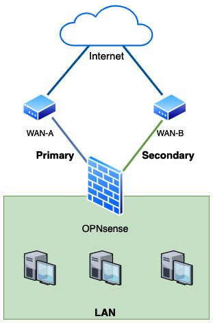
Figure 9.1 – Multi-WAN example scenario
As we can see in the preceding diagram, two WAN connections, A and B, are both connected to the internet and configured on OPNsense. WAN-A is configured in OPNsense as the primary connection and WAN-B as the secondary. If the primary fails, OPNsense will automatically change the Local Area Network's (LAN) outgoing connections to the secondary WAN in a failover manner.
Important Note
For simulating another WAN connection in a lab environment, you can add a new network interface and configure it on your OPNsense virtual machine (VM).
To configure the OPNsense VM to work in a failover manner, as proposed in the previous diagram, we need to adjust the VirtualBox network settings of our OPNsense VM:
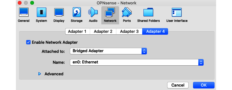
Figure 9.2 – Additional WAN interface, VirtualBox's example configuration
As you can see in the preceding screenshot, I have configured an additional interface using the Bridged Adapter option and selected my internet-connected network interface (en0). These network options can be accessed by clicking on the Settings button of your VirtualBox's VM. The configuration in your OPNsense will depend on the network's settings connected to this new WAN interface. If you are not sure, try to configure it as Dynamic Host Configuration Protocol (DHCP) first.
With your OPNsense configured with two WAN interfaces, it is time to go through the steps to set the failover configuration:
- On the webGUI, go to System | Gateways | Single and check whether both WAN interfaces have configured gateways:
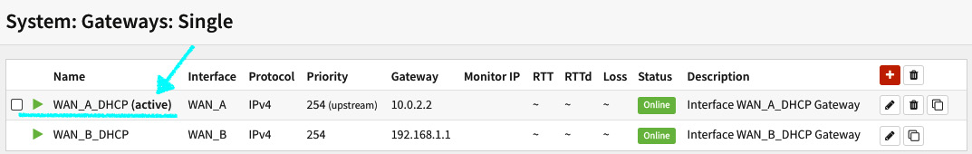
Figure 9.3 – System | Gateways | Single page
In the preceding screenshot, you'll note that the primary WAN (WAN_A) has the gateway address 10.0.2.2 (VirtualBox's gateway) and the secondary WAN (WAN_B) has the gateway configured as 192.168.1.1. As I mentioned previously, using VirtualBox, you can set one WAN using a Network Address Translation (NAT) adapter (WAN_A) and another one using a bridged adapter (WAN_B).
Let's check the options available on the gateway configuration page by clicking on the edit button (pencil icon):
On the gateway editing page (System | Gateways | Single), you'll find the following options:
- Disabled: Check this option to disable a gateway. Caution: this option can lock you out of OPNsense if you access it from a network that depends on this gateway to be reached.
- Name: This will define the gateway's name. If you are setting it for the first time, it's clever to name it with something that will make sense. Think twice before choosing a name; OPNsense does not allow you to rename an existing gateway.
- Description: This is an optional field. You set a gateway description here.
- Interface: Select which network interface will reach this gateway.
- Address Family: Select which IP version this gateway address will be set, IPv4 or IPv6.
- IP address: The gateway IP address.
- Upstream Gateway: This option defines whether a gateway can be set as the default gateway. For our example, this option must be selected.
- Far Gateway: This option will allow a gateway that addresses outside the network interface's subnet.
- Disable Gateway Monitoring: If this option is checked, this monitor daemon (dpinger) will not try this gateway to determine if it is alive. Consequently, it will always be considered online. Uncheck this option to our failover example configuration.
- Monitor IP: By default, OPNsense monitors the gateway's IP address. If you want to set a different IP address, we'll need to put it here. For example, if the gateway is blocking pings, or if you want to check not only whether the gateway is up but also whether the internet is accessible.
- Mark Gateway Monitoring: Check this option if it is a gateway to be forced to the Offline state (considered offline).
- Priority: This option allows you to set the priority for the gateway, where a higher priority will be selected as the default gateway (a lower number means higher priority).
- Advanced: Click on this button to expand the gateway's advanced configuration.
- Weight: This will set which weight the gateway will have while configuring in a gateway group. This setting can be used in a load balance configuration. For instance, if one link has 100 Mbps of bandwidth and the second has 25 Mbps, you may set the first one (100 Mbps) with weight 4 and the second one with weight 1; therefore, the larger link will get four times more traffic than the second one.
- Latency thresholds: Defines the range from the low to high latency thresholds (in milliseconds). The default values are From: 200 and To: 500. The From-To range will be set in a Warning state; any value below the From configured number will be considered Online, and values above the To configured number will be changed to the Offline state.
- Packet Loss thresholds: Like the preceding option, the From-To range will set the gateway in a Warning state. The default values are From: 10 and To: 20 (in percent). Any value lower than the From set value will be Online, and above the To value will be considered Offline.
- Probe Interval: This is the time interval expressed in seconds that each Internet Control Message Protocol (ICMP) probe will be sent. The default value is 1 second.
- Alert Interval: The time interval ( in seconds) before triggering a gateway condition change.
- Time Period: The time frame in which the results will be averaged. The default value is 60 seconds.
- Loss Interval: The time frame (in seconds) in which the packets will be considered lost.
- Data Length: Which size the ICMP probes will have (in bytes).
To save the gateway configuration, click on the Save button, then click on the Apply changes button.
After saving the gateway, you might notice two significant changes on the System | Gateways | Single page:
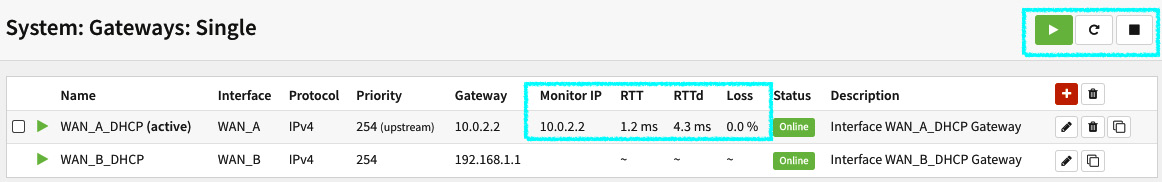
Figure 9.4 – Gateways with gateway monitoring enabled
As you can see in the preceding screenshot, the monitoring daemon will start to measure the gateway's latency, represented on the page by the round-trip time (RTT) column and the standard deviation, RTTd. The Loss column is how many packets (in percent) are being lost.
Remember to uncheck the Mark Gateway Monitoring option in the other gateway (WAN_B_DHCP).
Important Note
The RTTd, or RTT standard deviation is, in a simple manner of speaking, how much it varies over time.
To learn more about ping/ICMP standard deviation, check this link: https://newbedev.com/what-does-mdev-mean-in-ping-8.
The dpinger monitor daemon can be noted as running in the top-right corner of the page. You can also check whether it is running on Lobby | Dashboard:
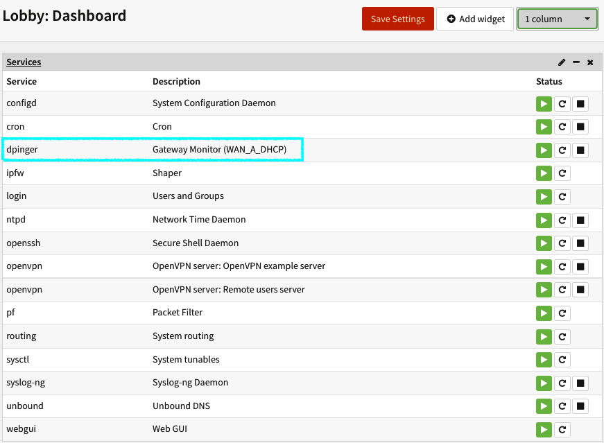
Figure 9.5 – The dpinger service running on the services widget (dashboard)
The preceding screenshot shows the dpinger service running on the service widget. You can check all the running services in this widget. On the Command Line Interface (CLI), you can check it using the pluginctl -s command.
Creating gateway groups
A gateway group can contain several system gateways inside it and the way we set each will define how this group will behave when some predefined condition is triggered.
Now that you have learned how to add a system gateway, we must create a group to work with it in failover and load-balance configurations later. Moving on with the configuration steps, let's now configure a group of gateways that will define how our configuration will behave, in this case, in a failover manner:
- Go to System | Gateways | Group and click on the + button to add a new gateways group. The following options must be set:
- Group Name: Set a name for the gateways group, for example, Failover_WANA_WANB.
Important Note
It is a good practice to name your gateways group by writing the primary gateway before the secondary (as in the preceding example). Thus, it will be easier to understand how the group is organized (which is the primary and secondary gateway).
- Gateway Priority: This defines each gateway priority considering a Tier level as explained in the following:
- Never: The gateway will not be used on this gateway group.
- Tier 1: The higher priority gateway. For our failover example, we'll set the WAN_A gateway by selecting this option.
- Tier 2 to 5: The following priorities define in which order each gateway will be triggered (the lowest number equals higher priority). For our example, we'll set the WAN_B gateway as Tier 2.
- Trigger Level: The trigger in which this gateway group will be ruled. The following options are available for selection:
- Member Down: A gateway will be considered down when it has 100% packet loss. The monitor daemon (dpinger) will monitor gateways using ICMP packets to define if it is alive or not. For our example, select this option.
- Packet Loss: Will be triggered when each gateway's defined packet loss thresholds are reached in advanced settings.
- High Latency: Will be triggered when each gateway's defined latency loss thresholds are reached in advanced settings.
- Packet Loss or High Latency: Will be triggered if one of these conditions is satisfied.
- Description: Fill with a description of this gateway group. For example, Failover group.
To finish, click on the Save button and then on the Apply changes button.
So far, we have configured an additional WAN interface, configured the basics of each WAN gateway, and created a gateway group to work in a failover manner. Now, it's time to learn about how policy routing works on OPNsense.
Policy-based routing
Unlike the static routes added to the system, policy-based routes will be created through firewall rules on OPNsense. In Chapter 5, Firewall, we explored firewall concepts and rules, but nothing related to using a gateway on rules, so now it's time to learn how to do that.
Before starting, to follow these steps, we'll need a host connected to OPNsense's LAN. If you are using VirtualBox as your lab platform, with an additional VM installed, follow these steps to connect it to the OPNsense LAN:
- To attach the VM to OPNsense's LAN, change the network settings to Host-only Adapter by editing the VM settings on VirtualBox:
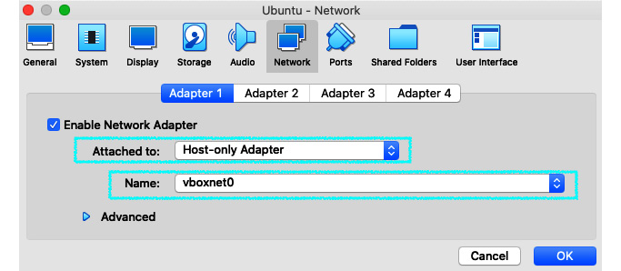
Figure 9.6 – Changing VM network settings to connect on OPNsense's VM LAN
- As we can see in the preceding screenshot, we need to select Host-only Adapter in the Attached to option. Choose the same network interface your OPNsense's VM uses as the LAN interface in the Name option. Following the steps we took in the earlier chapters, it should be vboxnet0.
Important Note
I'll use an Ubuntu VM host; feel free to choose your preferred operating system but pay attention to the commands demonstrated, as they will only work on Ubuntu (and probably most Linux distributions)!
- Start your VM, which is connected to the OPNsense LAN. From now on, I'll refer to the Ubuntu VM just as the host.
- Test the communication by running a ping test: ping <OPNsense LAN address>. If the ping replies, it works! Otherwise, check your VirtualBox network settings to ensure everything is configured as described in the previous steps.
- After checking that the communication is working, it's time to change the default gateway on the host to our OPNsense VM LAN's address. On Ubuntu, you can run the following:
sudo ip route del default
sudo ip route add default via <OPNsense LAN address>
Test whether the host is reaching the internet using OPNsense as the default gateway:
ping 8.8.8.8
With ping running on the host, check on OPNsense to ensure that the traffic is passing from the LAN to the internet; go to Firewall | Diagnostics | States and filter the destination address, 8.8.8.8:
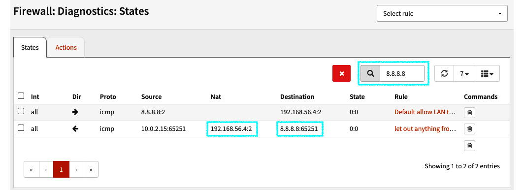
Figure 9.7 – Firewall | Diagnostics | States page showing the traffic from our LAN's host
- In the preceding screenshot, you will notice that the LAN's host address (192.168.56.4 in my lab) is using OPNsense as the default gateway to reach the public IP address 8.8.8.8.
With this, we finished the required steps to connect an additional VM as a LAN host to OPNsense. Now, it is time to move on with the policy-based routing rule to make the failover work!
Creating a firewall rule to enable the failover configuration
To enable the previously configured gateways settings, we need to add a firewall rule specifying the gateway group to enable the failover configuration. To do this, follow the given steps:
- Let's start editing the default allow all rule on the LAN; go to Firewall | Rules | LAN (the rule description is Default allow LAN to any rule).
- On the host, run traceroute to check the path the packets are following:
opnsense@ubuntu:~$ traceroute 8.8.8.8
traceroute to 8.8.8.8 (8.8.8.8), 30 hops max, 60 byte packets
1 _gateway (192.168.56.3) 0.817 ms 0.720 ms 0.806 ms
2 10.0.2.2 (10.0.2.2) 6.692 ms 6.660 ms 6.631 ms
3 * * *
4 192.168.15.1 (192.168.15.1) 12.545 ms 12.644 ms 13.841 ms
Important Note
In my lab, WAN_A_DHCP has the IP address 10.0.2.2, which is the OPNsense default gateway.
If your Ubuntu host doesn't have traceroute installed, you can install it by running apt install traceroute.
- To change the outgoing gateway from WAN_A_DHCP to WAN_B_DHCP, edit the same rule, and in the Gateway option, select the WAN_B_DHCP gateway, save, and apply the changes.
Important Note
Policy-based routing is only supported by rules with Direction set to in (inbound rules). For this reason, you need a LAN host connected to the OPNsense LAN interface to see things working.
- Back to the host, and run traceroute again:
opnsense@ubuntu:~$ traceroute 8.8.8.8
traceroute to 8.8.8.8 (8.8.8.8), 30 hops max, 60 byte packets
1 _gateway (192.168.56.3) 0.784 ms 0.997 ms 0.974 ms
2 192.168.1.1 (192.168.1.1) 2.408 ms 2.388 ms 2.378 ms
3 192.168.15.1 (192.168.15.1) 8.664 ms 8.638 ms 8.453 ms
4 * * *
- As you can see, the path was changed. Now, the packets are using the WAN_A_DHCP gateway (which is 192.168.1.1 in my lab). We just made the policy-based routing work! Let's now adjust the rule to achieve our goal: the failover!
- Edit the rule again, and now set the Gateway option to the gateway group we added previously: Failover_WANA_WANB.
- Repeat the traceroute step to ensure that WAN_A_DHCP (OPNsense's default gateway) is in use:
opnsense@ubuntu:~$ traceroute 8.8.8.8
traceroute to 8.8.8.8 (8.8.8.8), 30 hops max, 60 byte packets
1 _gateway (192.168.56.3) 2.238 ms 2.972 ms 4.418 ms
2 10.0.2.2 (10.0.2.2) 5.921 ms 10.674 ms 10.626 ms
3 * * *
- The traffic is back to the WAN_A gateway.
- Now, let's simulate that WAN_A is down by disconnecting its cable. In VirtualBox, you can do that by unselecting the network interface, as shown in the following:
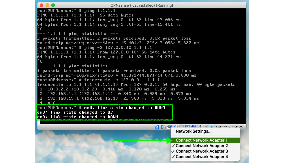
Figure 9.8 – Disconnecting a network adapter in VirtualBox
- After disconnecting the network interface, check on webGUI if the gateway changed to the Offline state; go to System | Gateways | Single to do that.
- Try traceroute again on the host:
opnsense@ubuntu:~$ traceroute 8.8.8.8
traceroute to 8.8.8.8 (8.8.8.8), 30 hops max, 60 byte packets
1 _gateway (192.168.56.3) 2.450 ms 2.203 ms 2.151 ms
2 192.168.1.1 (192.168.1.1) 4.363 ms 4.308 ms 3.954 ms
3 192.168.15.1 (192.168.15.1) 8.288 ms 9.896 ms 9.852 ms
4 * * *
- The traffic path has changed! Now, it is using the WAN_B gateway. The failover is working!
Even with this simple example, you can see that OPNsense works very well in a failover configuration. Users barely notice when a WAN link is down in a production environment, even with dozens of different protocols and thousands of hosts. I have excellent experience with failover scenarios (CloudFence's customers) that have five or more WANs with thousands of users; OPNsense is fantastic with that!
Now we have explored the failover configuration, let's look at the outbound load balance.
Load balance
The load balance configuration differs slightly from the failover, and it can also act as a failover when a gateway goes offline. The main idea of a load balance configuration is to send packets through the gateways in an alternate manner. How the packets will alternate the gateway will depend on some configurations:
- The gateway's tier level in the group
- The Sticky connections option in the Firewall | Settings | Advanced (the Multi-WAN section) – see Chapter 5, Firewall
- Firewall rule: Depending on the packet's match with the ruleset
To configure load balance, follow the given steps:
- Create a new gateway group using the same steps you have followed in the failover topic, changing only the Gateway Priority option for both gateways to Tier 1. Save and apply your changes.
- We will disable the Sticky connections option in Firewall | Settings | Advanced (the Multi-WAN section) only for testing purposes. Once this option will stick the connections based on the source host, and we have only one in our lab, it is safe to disable it to save time in our testing. In a production environment, it is not recommended to do that while using load balance, as this can break some internet connections (those that have source address check, for example, Transmission Control Protocol (TCP) and partially User Datagram Protocol (UDP)).
- Go to Firewall | Rules | LAN (the rule description is Default allow LAN to any rule) and alter the Gateway option to the new load balance gateway group we just created. Save and apply the changes.
- To do a test on the Ubuntu host, try traceroute 8.8.8.8:
opnsense@ubuntu:~$ traceroute 8.8.8.8
traceroute to 8.8.8.8 (8.8.8.8), 30 hops max, 60 byte packets
1 _gateway (192.168.56.3) 2.277 ms 4.733 ms 4.707 ms
2 10.0.2.2 (10.0.2.2) 4.685 ms 4.548 ms 4.512 ms
3 * * *
4 192.168.15.1 (192.168.15.1) 13.798 ms 14.349 ms 14.316 ms
- In the preceding output, we can see the traffic leaving the firewall using the WAN_A gateway.
- Now, repeat traceroute to another destination (1.1.1.1, for example):
opnsense@ubuntu:~$ traceroute 1.1.1.1
traceroute to 1.1.1.1 (1.1.1.1), 30 hops max, 60 byte packets
1 _gateway (192.168.56.3) 7.422 ms 7.342 ms 7.305 ms
2 192.168.1.1 (192.168.1.1) 16.747 ms 16.715 ms 10.0.2.2 (10.0.2.2) 16.682 ms
3 192.168.15.1 (192.168.15.1) 54.729 ms 58.178 ms *
Notice that the path changed! Our load balance configuration is working!
These were quite simple examples, but in a production environment, a lot of complexity might be added, and some issues can appear. Let's now see some examples of how to troubleshoot them.
Troubleshooting
Let's look at some of the common issues while configuring load balance and failover configurations:
- Failover/load balance isn't working: The tier 1 WAN line goes down, but the traffic is still trying to leave the firewall through it. OPNsense, by default, will set the gateway's IP address as the monitor IP address; for instance, let's suppose the WAN line was interrupted somewhere between the customer and the Internet Service Provider (ISP). The router/modem will be still alive and responding to ICMP requests. This can happen because the gateway's IP address is the local network interface of the router/modem, and it won't be down in this case, so the OPNsense monitoring daemon will consider it online; therefore, the condition to change to another WAN will not be triggered. To avoid this issue, always set the monitor IP address to an ISP WAN's cloud address; this way, when the communication between the ISP's router/modem is interrupted, the failover will work as expected. For internet gateways, ensure the Upstream Gateway option (System | Gateway | Single) is checked in each configured gateway in the group.
- The monitor IP address is offline, even with the WAN line as Online: This is the opposite of the preceding condition. Before setting an alternate monitor IP address to a gateway, test whether it replies to ICMP packets. Another common issue is when a host stops responding to ICMP packets, so choosing the right host as the monitor IP address is essential to avoid future headaches.
- OPNsense has internet access, but hosts using the failover/load balance rule don't: This can happen because OPNsense and all services running on it will use the default gateway to access the internet. The option that will configure OPNsense to change the default gateway in a multi-WAN configuration is Gateway switching (in System | Settings | General). Once a gateway group is set to follow the tier level of each configured gateway, a policy-based routing rule may send traffic to a different gateway that isn't working well. So, in cases like that, it is crucial to compare the gateway group's configuration and OPNsense's in-use gateway.
- Always check the logs: The dpinger daemon has a log file that can help you troubleshoot issues related to gateways. You can view this log file on webGUI at System | Gateways | Log File.
These are some examples of failover/load balance issues we face daily while working with OPNsense. Sometimes a problem can be a combination of other ones. It will depend on the complexity of the OPNsense configuration. You can always count on the community's support in the forum to help you!
Summary
In this chapter, we have explored the failover, load balance, and policy-based concepts. Now, you can understand, create, and manage gateways, groups of gateways, and firewall rules using them. You also learned how to troubleshoot common issues involving failover, load balance, and gateways on OPNsense. In the next chapter, we will go through the reporting features available on OPNsense!