
Inscrutable workmanship that reconciles Discordant elements, makes them cling together in one society
Lines composed a few miles above Tintern Abbey, William Wordsworth
CONTENTS
16.2.2 Manufacturing Technology
16.2.2.2 Post-Oxidized Internally Oxidized Parts (Process B 1.0)
16.2.2.3 One-Sided Internally Oxidized Parts (Process B 2.01)
16.2.2.4 Preoxidized Internally Oxidized Parts (Process B.2.02)
16.2.2.5 Powder Metallurgical (PM) Silver Metal Oxides (Processes C and D)
16.2.3 Electrical Performance Factors
16.2.3.2 High Current Inrush DC Automotive and AC Loads
16.2.3.4 Silver-Tin Oxide Type Materials and Additives
16.2.3.6 Interpreting Material Research, Example from Old Silver Cadmium Oxide Research
16.2.4 Material Considerations Based on Electrical Switching Characteristics
16.2.4.1 Erosion/Materials Transfer/Welding
16.2.6 Erosion/Mechanisms/Cracking
16.2.8 Interruption Characteristics
16.3.1 Manufacturing Technology
16.3.1.1 Manufacturing Technology/Press Sinter Repress (Process D 1.0)
16.3.2 Material Technology/Extruded Material
16.3.2.1 Material Technology/Liquid Phase Sintering (Process D 2.0)
16.3.2.2 Material Technology/Press Sinter Infiltration (Process D 3.0)
16.3.3 Metallurgical/Metallographic Methods
16.3.3.1 Metallurgical/Metallographic Methods/Preparation
16.3.3.2 Metallurgical/Metallography/Quantitative Analysis
16.3.4 Metallurgical/Structure/Strength and Toughness
16.3.5 Electrical Properties (EP)
16.3.5.1 EP/Arc Erosion/Microstructure and Properties
16.3.5.2 EP/Arc Erosion/Silver Refractory
16.3.5.3 EP/Graphite Additions to Silver Tungsten and Silver Tungsten Carbide
16.3.5.4 EP/Copper Refractory Metals
16.3.5.6 EP/Composite Refractory Materials/Contact Resistance
16.4 Vacuum Interrupter Materials
16.6.2 Hard Silver and Silver–Copper Alloys
16.7 Silver-Nickel Contact Materials
16.8 Silver Alloys and Noble Metals
16.8.1 Palladium and Silver-Palladium Alloys
16.9 Silver-Graphite Contact Materials
The electrical contact field is mature yet material research continues in certain areas like silver metal oxides albeit at a lower level than twenty years ago. In the United States, Europe, and Japan, there are fewer university material research programs than in the past, but in China there are contact research activities at several universities bringing many new researchers to the contact field. In the last few years, the largest driving force for material research in the contact field has been the high price escalation and volatility of the noble and precious metal markets especially for silver and gold. In the next section on silver metal oxides another factor, RoHS (Restriction of Hazardous Substances) compliant materials, will be discussed as a factor for the direction of research. For some materials, it will be seen that little change has taken place while for others a wide variety of options are offered.
In this chapter, the various types of materials utilized for arcing contacts are described in terms of chemistry, general physical properties, and material structure. Some general information is given regarding the manufacturing technology that is utilized to make these materials. This is important to understand since some of the materials can be manufactured by several widely differing manufacturing processes and, as a result, materials with identical chemical compositions can have very different performance characteristics. This chapter also provides some performance information relating the materials to electrical loads and specific applications.
The materials are divided into different categories for this discussion on the basis of general similarities in chemical composition and metallurgical structure. Within each category the more common compositions are discussed. Many variations of material types may exist for each general composition as a result of process differences used by different manufacturers for making these contact compositions and also as a result of small differences in chemistry from the use of different minor additives in making these materials. For example, a common 90/10 wt% silver–tin oxide material may be made by using over five different processes without additives or with additives like In2O3, Bi2O3, WO3, or more. From this, it is evident that over 20 different permutations of this general composition can exist.
As a result of the large variety of material types that are available, the switching device engineer may be overwhelmed by choices. In Section III of this book, it is shown that arcing contact switching involves many mechanical and electrical variables. With many numbers of choices being possible for matching device and material parameters, it is possible to give general guidelines for selection of materials for specific devices, but not absolute guarantees for material–device combination performance. For most applications, more than one material type can be used to perform the electrical switching functions successfully. The grouping of the materials into categories as shown in this chapter is aimed at simplifying the understanding of material choice differences and helping the engineer more quickly to narrow down the number of candidates that should be investigated. Once a specific material or range of materials is chosen, electrical tests can be made in the actual device or application to assess the performance of the material.
The word “material” as opposed to “alloy” is used in this section to describe the contact metal and metal oxide combinations. The word alloy is sometimes used in a general sense to describe these combinations, but many of the contacts are not alloys but instead are mixtures of metals or metals and ceramics that have either very little or no mutual solubility, thus they don't form true alloys. Since arcing contacts are made from many types of materials and material combinations, many different kinds of processes are involved in this technology. In order to better understand and discuss process technology, the various kinds of applicable manufacturing processes are divided into general process categories. The first major breakdown is the division into two major process differences, alloy and cast versus powder metallurgical. As shown in Figure 16.1, the processes can be divided further into four main process types designated as Processes A, B, C, and D. The sub-processes of these main processes can be subdivided into many variations much more than shown in the illustration. Although most contact material processes fit into one of the four processes shown there are some new technical methods being investigated such as “cold spray” for silver metal oxides that may have some future potential as reported by Rolland et al. [1].
Materials that are made by Process A, alloy and cast and form, in general show the least material variations among different manufacturing sources compared to materials made by processes B, C, or D. For example, Process A, a silver–copper alloy made to the same composition limits by two different sources, will have very similar metallurgical structures after casting, since alloying is on an atomistic basis and proper casting produces fully dense parts. In contrast, a material such as silver–nickel made by two different companies both using the same general powder metallurgical manufacturing methods, for example, Process C, is unlikely to be similar unless the two companies have identical starting powders, mixing processes, pressing parameters, and sintering methods. Variations in these process steps will cause structure variations in terms of silver and nickel distribution and retained porosity. If the two companies had made the silver–nickel materials using two different general processes, process C versus process D, an even larger difference would be expected in the material properties. The materials made by process C would have a higher density and more grain directional properties than materials made by process D.
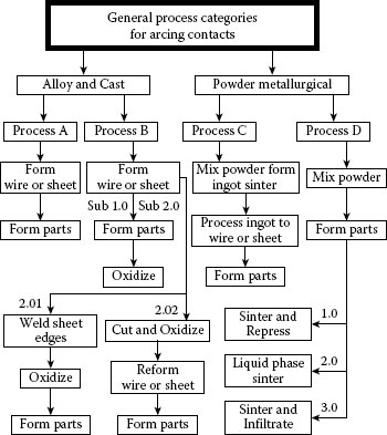
FIGURE 16.1
Processes used for making contact materials.
From the above examples the following deduction can be made. As opposed to materials such as steel and copper alloys where many generic classifications exist, many contact materials differ significantly although they are of the same general composition. As a result, it is not a recommended practice to substitute contact materials of the same composition made by different manufacturers without proper electrical testing of the material in the device for which its use is intended.
In the following sections of this chapter, some of the typical properties of the materials are listed in tables. A further listing of properties is given in Chapter 24. The properties listed in brochures of several manufacturers along with available standards were utilized to determine typical values for composition, density, hardness, and conductivity [2,3,4,5] For material hardness the Vickers scale is used although many companies list these values using the Rockwell scale. Most individual contacts are too small in size, however, for accurate measurement using the Rockwell scale. Vickers is therefore the better choice, because it allows comparison of hardness regardless of the contact size, and, more importantly, the Vickers values allow theoretical calculation of contact resistance using the following equation from Chapter 1 (see also Chapter 24, Section 24.2[f]):
(16.1) |
H is hardness in N (Newtons) mm−2, F is force expressed as N, ρ is resistivity in Ω mm. Note: Since many contact catalogs list properties in terms of Vickers, kg mm−2, you can convert these values to N mm−2 by multiplying the value by the factor 9.81, also most catalogs use conductivity (m Ω−1 mm−2) that can be converted to resistivity in terms of Ω mm by taking the reciprocal of the value and multiplying it by 10−3. For example if a silver cadmium oxide contact has hardness listed as 80 HV and a conductivity of 48 m Ω−1 mm−2. The constriction resistance for a 0.5 N contact force is estimated as follows:
Silver metal oxides represent one of the most popular and important categories of arcing contact materials. There are many types of these materials in terms of both chemical composition and material structure. Table 16.1 shows some typical compositions with hardness and conductivity values for comparison. Shen et al. [6] give an historic review of silver metal oxide evolution since its beginning in the late 1930s and show examples of over 50 different chemical compositional systems patented or investigated. Silver metal oxide materials are composite materials consisting of a silver matrix containing a dispersion of fine particulate composed of single oxides or multiple oxides. Since the metal oxide phase has little or no solubility in the silver, the particles strengthen the contact structure without reducing the matrix conductivity.
Today, silver–tin oxide type material is the most popular contact of the metal oxide type, and it has replaced silver cadmium oxide to a large extent. There are several driving forces for the change to silver–tin oxide from silver cadmium oxide. Cadmium has been identified as a hazardous material and restrictions have been placed on it for many applications. The European Union for RoHS (Restrictions of Hazardous Substances) standards more recently allowed the use of CdO in electrical contacts as a temporary exception until the development of substitute materials is complete. This makes the future unclear about the use of silver cadmium oxide and certainly legal battles are possible. Another factor driving the conversion is improved electrical erosion resistance in many applications using silver–tin oxide type materials compared to silver–cadmium oxide, thus saving precious metal material. By the beginning of 2012, most all European device manufacturers and Japanese device manufacturers have converted to silver–tin oxide type materials yet in North America many devices still use silver–cadmium oxide. For automotive applications cadmium oxide contacts are banned worldwide. As a result of these factors, less emphasis will be put on silver cadmium oxide and more on the replacement materials for silver cadmium oxide which have been successful in most applications. Since there are many types of silver–tin oxide materials the generic term, silver–tin oxide will be used to describe the whole family of silver–tin oxide types. Therefore, in this section reference to silver–tin oxide will include AgSnO2, AgSnO2/Bi2O3, AgSnO2/In2O3, AgSnO2/WO3 and other Ag-SnO2/XX combinations.
TABLE 16.1
Some Typical Silver Metal Oxide Contact Compositions and Properties and Additives
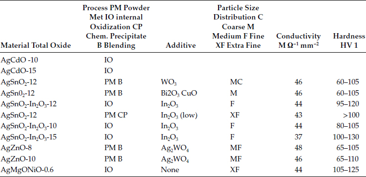
See Table 24.5 for a broader listing of properties [1,2,3,4].
For the indium oxide, the IO materials have greater than 2.5% indium oxide and the PM grades can have any level, the (low) statement means less than 1%.
16.2.2 Manufacturing Technology
Besides the differences in chemical compositions for silver metal oxides there are many differences in material structure owing to the many processing variations possible for manufacturing these materials. In order to have a good discussion of these materials it is important to understand the basics of the manufacturing technology. This section describes the general common processes used today. The processes for making silver metal oxide contacts can be first divided into two major categories: (1) internal oxidation (IO) (Process B), or (2) powder metallurgical (PM) (Processes C and D), see Figure 16.1.
Starting in the 1970s, different forms of silver–tin oxide materials were developed in Europe and Japan simultaneously. In Europe, most of the work was done using a PM approach. In Japan, all of the work was by IO as the manufacturing base. More recently, many variations of both processes are used around the world. Both processes have pros and cons with the PM approach being a little more flexible for additive additions.
Internal oxidation consists of heating a silver alloy to a temperature below the melting point and allowing oxygen to diffuse into the alloy and react with solute atoms to form metal oxide particles. Following is an example of an equation for the oxidation of silver–cadmium alloy to become silver–cadmium oxide. This shows a parabolic relationship between oxidation depth and oxidation time and the oxidation of silver–tin oxide also has a similar parabolic relationship. Wagner [7] and Freudiger et al. [8] developed Equation 16.2 for oxidation of silver–cadmium alloys in the range 700–900°C. Equation 16.2 below is corrected for a typo in the original paper and also has the constant changed to yield mm versus cm:
(16.2) |
where X = oxidation depth, mm, K = derived constant (8.96 10−4 cm2 s−1), A = activation constant (21,000 cal), R = gas constant (1.987 cal (°kg mole−1), T = absolute temperature, P = partial pressure of O2 (cm Hg) t = time, and NCd = mole fraction (atomic% Cd).
Example for Use of Equation 16.2: Compare the depth of oxidation for a silver–cadmium oxide alloy 10% by wt. CdO for oxidation at both 750°C and 850°C at atmospheric pressure for 10 h. An AgCdO 10 wt.% CdO needs a silver–cadmium alloy 9.55 wt.% Cd or by conversion 9.2 atomic% Cd. Use Equation 16.2 with the following values:
Other silver metal oxide systems also follow the same general parabolic oxidation depth versus time relationship, but some systems like silver–tin oxide are more difficult to oxidize as a result of the formation of a tin oxide scale on the surface which passivates the surface to further oxidation. In order to solve this problem, silver–tin alloys are doped or alloyed with several different additives to aid in oxidation. Grosse et al. show the influence of additions of Bi, Cu, and In on the kinetics of oxidation of silver–tin alloys [9]. The amount added can equal or exceed the tin content and these materials are considered to be double oxides.
Additives are also used for altering and controlling the distribution of oxide particles for both silver tin oxide and silver cadmium oxide materials. Numerous patents exist for such additives [6]. Some of these additives serve as nucleation agents by providing sites for particle formation and refinement of the particle size distribution.
16.2.2.2 Post-Oxidized Internally Oxidized Parts (Process B 1.0)
In the early days of internal oxidation, the most popular process was to oxidize individual parts after they had been formed. This process is commonly called post-oxidation. For this type of oxidation, oxygen is diffusing from the outside toward the center of the part and the solute element diffuses in the opposite direction. This combination of opposite directional diffusion results in a depletion zone, void of metal oxide, in the center of the part. For AgCd, this zone is about 4% of the material thickness for oxidation at 800°C [8] see Figure 16.2. Silver–tin oxide post oxidized parts show similar depletion zones.
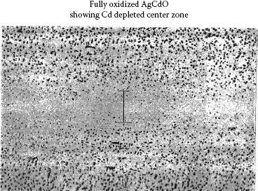
FIGURE 16.2
Post-oxidized internally oxidized silver–cadmium oxide cross section.
From Equation 16.2, it can be seen that the time of oxidation varies with the square of the depth of oxidation. As a result of this relationship, a particle size gradient is created during oxidation. As oxidation proceeds deeper into the part, particles become coarser since oxygen is arriving at the oxidation front at a slower rate relative to the solute atoms. Thick parts which require very long oxidation times can have excessive particle size growth if not oxidized under compensating conditions. From Equation 16.2, it also can be seen that the oxidation rate increases as a function of the partial pressure of oxygen, P1/2. Jost and Santale describe a process of gradually increasing the oxygen pressure as the oxidation front progresses deeper into the parts in order to increase the oxidation rate and keep the particle size uniform and in the desired size range [10]. Also, as had been mentioned above, additives are used for controlling the particle size distribution.
Another characteristic of internal oxidation is the potential for defects called thermal arrest lines. These are lines parallel to the contact surface containing high concentrations of oxide particles. The lines are caused by abrupt changes in the oxidation rate, usually as a result of furnace malfunction such as a temporary temperature drop. The slowing of the oxidation rate allows solute atoms to penetrate beyond the oxygen front and temporarily reverse the direction of oxidation. After equilibrium is re-established and the oxidation again proceeds deeper into the part, the area in which the reversal occurred is left with a high concentration of oxide particles. Since the oxide particles are brittle, if the particles are concentrated and contiguous, the thermal arrest area will be prone to cracking or delaminating from thermal stress created by the heat from high current arcs.
Today, far fewer parts are made by post oxidation which produces an expensive monolithic silver metal oxide structure as opposed to a bimetal structure. Most of the background work on this process was done on silver–cadmium oxide yet most of this is applicable to silver tin oxide materials. The following shows why depletion zones are not as problematic as once thought. For contacts with depletion zones only 0.05 mm or less thick, it is questionable that the depletion zone has a detrimental effect. By the time the contact has eroded to the depletion zone, the surface of the contact has developed a new microstructure that bears little resemblance to the original microstructure and consists of a heat-affected layer with deposits of arc debris. Kim and Peters show cross sections of arced silver–cadmium oxide contacts in attempting to relate this surface melt layer, the bulk material microstructure, and the erosion process [11]. Their work shows that after arcing, the surface consists of oxide aggregates and platelets much coarser than the original oxide particles that are fed into the surface to form this layer. Also since the heat of the arc allows segregation of the CdO from the silver, large areas depleted of CdO exist at and just below the surface. Similar surface structures are seen in silver tin oxide materials after extensive endurance switching see Figure 16.3 [12] and also Figure 10.48 in Chapter 10. Certainly the chemistry of the arced surface layer is related to the microstructure that feeds into this surface, but the transition is more gradual than would be expected. The erosion process, as discussed in Chapter 10, is not like a machining operation, just cutting off surface material and leaving the structure below as the new surface. The erosion process is much more complicated and involves melting of the surface, arc deposits and transfer of material between anode and cathode, a heat-affected zone deeper into the surface, the under melt zone, and more. As discussed later in this chapter, the surface-layer characteristics are affected by both electrical load and material variables. The point of this discussion is that, as a result of thin depletion zones, it is unlikely that a surface completely depleted of metal oxides will be formed by the erosion process, but instead a surface with a reduced oxide content.
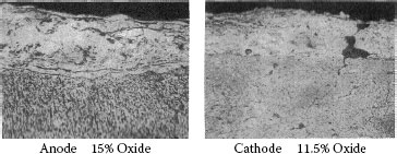
FIGURE 16.3
An illustration of how the microstructure of the equilibrium melt layer established on the surface of a contact during endurance testing can differ from the mictrostructure of the bulk material. Cross section of silver metal oxide contact surfaces after 300,000 operations at 30 A 12 V dc inductive load.
16.2.2.3 One-Sided Internally Oxidized Parts (Process B 2.01)
This once very popular method is rarely used and consisted of welding two sheets of alloy together and oxidizing from one side. This eliminated the depletion zone in the middle of the part. Associated with this and internal oxidation in general is a problem of getting a very thin silver layer on the surface of the contact as a result of the oxidation process. This problem is discussed by Pedder for Ag–CdO and by Shen and Lima for Ag–SnO2In2O3 [13,14]. This layer is more extensive for the silver–tin system. The extent of this problem also depends on the method of processing. The manufacturer of the contact must use special techniques to control this problem. Normally the cleaning process removes this layer.
16.2.2.4 Preoxidized Internally Oxidized Parts (Process B.2.02)
A very popular variation of the internally oxidized method for making silver metal oxides is to form small pieces of the alloy, internally oxidize the pieces, compact and extrude the pieces into wire or strip and form discrete parts from the wire or strip. Some manufacturers refer to this product as “preoxidized metal oxide parts,” referring to the fact that the material is oxidized before the part is formed. There are many variations in methods used to form the small pieces of alloy for oxidation; for example cut wire, cut strip, atomization of melt to form shot, and more. The preoxidized process produces a product that is more heterogeneous in metallurgical structure throughout the contact body than post-oxidized parts. The extrusion of internally oxidized materials after oxidation produces material that is more ductile than material in the oxidized state before extrusion. This difference is very great for silver–tin oxide type materials. The metallurgical structure of the material is much different after extrusion and the electrical performance of the material can also be changed. This process has become the most popular type of process for making IO silver tin oxide wire and preoxidized strip since it offers materials with a uniform microstructure and good formability compared to other silver tin oxide processes. The use of large amount of machine made composite rivets which can use preoxidized wire has significantly increased the use of this IO process.
16.2.2.5 Powder Metallurgical (PM) Silver Metal Oxides (Processes C and D)
A powder metallurgical process was the first method used for making silver metal oxide contacts. Today many types of powder metallurgical processes exist for making silver metal oxide materials. Processing among companies can differ significantly in techniques for powder production, pressing, sintering, and forming. Some of the more common options in manufacturing technology for powder metallurgical silver metal oxide contacts are reviewed in this section.
For powder metallurgical processes, the final properties of the materials are a product of many parameters including, powder size and characteristics, blending methods, pressing techniques, sintering processes, and methods of further consolidation [15,16,17]. For powder production, care must be taken to control contamination from retention of salt traces or chemicals used in production, as low levels of substances like alkali metals can cause electrical interruption problems, discussed later in this chapter.
16.2.2.5.2 PM/Blends of Elemental Silver and Metal Oxide
The simplest of the powder processes involves blending silver powder and metal oxide particles. The silver powder technology itself is complex and several different methods exist for making powder. Each technique, electrolytic, chemical precipitation produces powders with different particle size distributions and blending characteristics. Chemically precipitated powders in the low micron size ranges are common for this type of use. Metal oxide powders or compounds that break down during sintering to form metal oxides are used for blending with silver powders. For blending, there are sophisticated milling techniques for better intimate mixtures of the silver and metal oxides. Both the size and the degree of agglomeration of the powders are important for controlling the final microstructure in terms of metal oxide distribution in the silver matrix.
16.2.2.5.3 PM/Composite Powders
Today, many processes exist for producing composite silver tin oxide type powders. Most companies are very secretive about these types of processes. Chemical precipitation is one popular method where silver and metal oxides are precipitated from metal salts. These powders allow the formation of finer particle size distributions of the tin oxide and other oxides in the silver matrix. Another method that has been used is the internal oxidation of alloy powder (IOAP), for example fine atomized alloy particles containing silver, tin, and other additives. Pedder et al. used these types of processes for silver cadmium oxide powders [18]. Sometimes these methods produce particles so fine they are difficult to process and form without producing defects in the structure. The use of a process called Oswald ripening can coarsen the structure by heating pressed parts and allowing particle growth through fine particles dissolving and re-precipitating on larger particles [19].
16.2.2.5.4 PM/Processes/Press, Sinter, Repress (Process D 1.0)
This is one of the first basic metallurgical processes utilized for making silver metal oxide contacts. This process normally does not produce fully dense parts and is not used as much as the other PM processes discussed this section. Any of the above powder systems can be used with this process. The process consists of (1) compacting the powder in a die into the shape of the desired contact, (2) sintering the pressed compact to increase the strength, and (3) repressing the compact to increase the density. With this process significant porosity normally is left in the contact body after processing, with a range of 1–5% porosity being common.
If the pressing of the powders before sintering is done at too high a pressure, gas can be entrapped in the compact that affects the sintered structure. Gas can also be entrapped in the structures during repressing if there is a large change in density between sintering and repressing. On heating the structure after repressing it may expand if too much gas is entrapped. Electrical erosion tests were conducted by Lapinski for comparing silver–cadmium oxide contacts made both with and without excessive entrapped gas from processing variations [20]. The tests showed higher electrical erosion rates for the contacts with the entrapped gas.
16.2.2.5.5 PM/Wrought PM/Press Ingot Sinter, Extrude, Form (Process C)
This process is commonly referred to as wrought powder metallurgical for silver metal oxide material. As a result of the large amount of work put into the material the contacts made by this process are normally fully dense. The consolidation methods may vary with manufacturers, extrusion being the most common and other methods, such as swaging of ingots, also being used. The materials made by this process, depending on the characteristic of the starting powders and forming methods, can be anisotropic. Depending on the particle size and characteristics, the particles elongate and align parallel to the extrusion direction. Poniatowski and co-workers [21,22,23] studied anisotropic AgSnO2 extruded material and found electrical erosion resistance improved for contacts made with the face perpendicular to the oxide particle elongation than for contacts with the particle elongation parallel to the face, see Figure 16.4. As a result of economics, however, most products made by the wrought PM process are made with the contact face parallel to the particle elongation or extruded into wire which is later formed into both monolithic and bimetal rivets or other forms.
16.2.2.5.6 Summary of Metal Processing Differences
The basic processes of IO and PM contact metal oxide production are quite different. The structures produced by IO post oxidized material and PM press, sinter, and repress materials are very different in appearance and microstructure particle distribution. On the other side the extruded IO and PM processes can produce very similar metallurgical structures. For silver–tin oxide type materials the IO process normally needs some additive in order to allow efficient oxidation to take place. The PM system is more flexible and only uses additives to enhance the properties of the contact material. Both processes need good controls to insure consistent product is made. Years ago the PM process resulted in coarser oxide dispersions than those made by the IO process even in extruded wire. Today most of the European PM manufacturers have developed wet chemical precipitation processes for making composite powders, silver and metal oxides. These powders appear to be finer and more uniform than PM blended powders. As a result of this many PM materials now have particle size distributions similar to IO materials. It is important to understand the basic process that is being used to make a product and record the microstructure characteristics of any product that you are testing and evaluating. For electrical performance the chemistry is important but also the microstructure has a large influence.
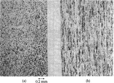
FIGURE 16.4
Silver–tin oxide materials: cross section (a) perpendicular to tin oxide fibers and (b) parallel to tin oxide fibers.
16.2.3 Electrical Performance Factors
A. Electrical switching parameters and load considerations
Before going into a discussion of the effects of different additives and chemistries for silver tin oxide materials a short discussion will be made about some major differences in erosion characteristics with different electrical loads and switching conditions. When you look at the results of some research on contact performance you must consider the electrical parameters that were used to reach the results, since the results, may not apply to the parameters used in another device.
For a single switching operation for opening the contacts there is a transition in the direction of material transfer as a function of the arc erosion going from anodic to cathodic transfer, [24,25]. In the initial opening stage when the gap between the contacts is small, less than ~5–10 microns, short arc, the anode is eroding and there is some transfer of material to the cathode. As the gap between the contacts becomes larger the transfer of material during arc erosion reverses. For low voltage DC applications like automotive switching at 13VDC depending on the type of electrical load the accumulated material transfer can be significant. In AC, since the polarity changes with each operation if the timing of switching is random there is no cumulative material transfer effect (see Chapter 10, Section 10.3).
16.2.3.2 High Current Inrush DC Automotive and AC Loads
A high current inrush load like a lamp load may have a current as high as ten times the normal current for the first few milliseconds after contact closure. Most times there is some contact bounce that takes place after initial contact closure. This bounce will be associated with a high current arc and electrical erosion as a result of the arc will take place. For an automotive type DC load the arc will be short and anodic burning a crater in the anode and depositing material transfer onto the cathode contact. Since the contact opening part of the switching cycle will be at normal current the net result of endurance switching in this case will result in material gain on the cathode and material loss on the anode. For AC switching the same current with the polarity per operation random the erosion should result in a material loss for both contacts and no buildup of transfer on either contact (see also Section 10.3.5).
16.2.3.3.1 DC Automotive Inductive Loads
For these types of loads the induction in the circuit will cause a lag of the current buildup of several milliseconds, 3–8 typical. This means for switching closure under this load little erosion takes place even with moderate switching bounce taking place. For opening it is a different story since the inductance will prolong the arcing time and length of the arc. For a long arc on opening the arc will start out as being anodic and later make a transition to being cathodic with the material transfer changing from anode loss and cathode gain to cathode loss and anode gain. Chen and Witter [26,27] showed that the contact opening velocity and maximum contact gap in a device also have a significant effect on the erosion results under these conditions. They show the erosion of a silver–tin indium oxide to go from being anodic erosion to cathodic erosion as the opening speed changes from 0.47 m/s. to 1.28 m/s. It also should be noted that much of the fundamental testing is done using model switches which allow gathering of information not possible in actual commercial devices like sticking and welding force and actual weight loss. Sometimes these devices open and close the contacts at very slow speeds that are far slower than commercial devices and thus the result may not apply to the real world of switching.
16.2.3.3.2 Resistive Loads with no Inrush
The resistive loads have results that are mainly in between the examples shown for lamp and inductive loads.
B. Additive factors
From the above examples it should be apparent that electrical test results on materials and additives in materials will be subject to the electrical parameters and load type used in the testing and that loads differing from the tests performed may not agree with the results of a specific research.
16.2.3.4 Silver–Tin Oxide Type Materials and Additives
Silver–tin oxide type materials have become the most popular arcing materials for relays and contactors worldwide. Besides the many different variations in process for making the materials there is a large variety of additives used to adjust the properties of the materials. In this section we will discuss the most popular additives for silver–tin oxide materials: indium oxide, bismuth oxide, copper oxide, tellurium oxide, and tungsten oxide. The effect of the additives is a complex subject, since not only are the effects influenced by the manufacturing process and electrical application but also some of the additives interact with each other which change the effects. A complex study on combinations of CuO, Bi2O3, and WO3 show the effects on ductility, arc erosion resistance, and contact resistance change significantly with different ratios combinations of these three additives, [28]. This means one must take into account the total package of additives being used.
16.2.3.4.1 Indium Oxide Additions and Tellurium Oxide
Indium oxide did not start out as an additive to silver tin oxide for the purpose of improving properties but instead as an aid to the oxidation process. The addition of indium to silver tin alloy prevents the formation of an imperious oxide wall from forming during the oxidation process. Silver tin indium oxides are still the most popular type of silver tin oxide type materials manufactured in Japan and China.
For AC contactors most manufacturers in Japan switched to silver tin indium oxide contacts in the late 1970s and 1980s. Since these contacts had a little higher contact resistance than silver cadmium oxide the companies increased the contact force in the contactors to compensate for the higher resistance. Besides for replacing cadmium as a black-listed element the companies were able to use smaller contacts and save on silver since the silver tin indium oxide material had a lower erosion rate. In 1992, Hetzmannseder and Rieder [29] did a study comparing erosion of silver tin indium oxide contacts and European silver tin oxide contacts that did not contain indium in a test device that simulated contactors operating in an AC-3 mode, high inrush, 6×, with normal break. The amount of erosion that take place in AC-3 testing is related to the amount of make bounce that takes place in closing of the contacts. Their testing controlled the bounce so a good comparison could be made for different materials. They showed a much lower erosion rate for the silver–tin indium contact than the European silver–tin oxide without indium and made by powder metallurgy. It should be noted that for bounce erosion the arc is short and the efficiency of material transfer between the contacts becomes a factor in determination of the actual erosion loss. This showed an advantage for the indium oxide addition for promoting a lower erosion rate in AC switch owing to good transfer characteristics. Much more recently Mützel and Niederreuther [30] did a comparison of some newer and older PM materials and included IO silver tin indium oxide. For erosion they did testing using an automotive inductive load and showed that the erosion rate of the silver tin indium oxide IO materials was much lower than the old PM material and similar to newer materials with other additives. Although this testing was DC testing the inductive load used had material transferring in both directions, from anode to cathode and as the contact gap widened from cathode to anode.
Although the indium oxide seemed to give an advantage for erosion on AC loads and certain DC loads it became somewhat problematic for high inrush DC loads. For lamp loads in DC automotive circuits the erosion of the contacts was mainly involved with contact bounce on closing since you had a large current on closing and normal current on opening. In this case, the material transfer that took place was always from the anode to the cathode and since the polarity stayed the same you had a buildup of material on the cathode. If the material had a high efficiency for transfer (i.e., good sticking of transfer material to the cathode), there was a higher probability of developing a condition called pip and crater erosion. In 1996, Witter and Polevoy [31] tested automotive relays with silver tin indium oxide contacts using a lamp load. Tests were run on the same batch of relays with some relay having a cover on enclosing the contacts and other relays with no covers just exposed to open air. These tests were done since some tests using a model switch were not duplicating the life results seen in the relays. The results of the testing were dramatic with regard to tests with and without relay covers. The relays with covers had long endurance life and those without covers failed very early as a result of severe pip and crater erosion. The relays with covers did not form pip and crater erosion as a result of organic outgassing from the plastic which activated the contact surface from carbon deposits of the organic gas and the arc. This phenomenon will be explained later in this chapter in the section on material transfer and in Chapter 19. The point learned from this work was that silver tin indium oxide had a high potential for forming pip and crater erosion which is very detrimental for DC high inrush loads.
Some companies in Japan that made silver tin indium oxide also discovered that a problem existed under certain applications with silver tin indium oxide. Work began on additives for improving this condition. In the early 1990s, several patents came out for adding tellurium to silver tin indium alloys for improving the performance of silver tin indium oxide materials. Some of the patents have expired and little has been published or explained about the actual phenomena. Witter and Chen [32] did an investigation using a model switch with a lamp load for comparing the performance of silver tin indium oxide materials with and without an additive of <0.5% Te which forms an oxide during the oxidation. The results showed much less pip and crater erosion for the silver tin indium oxide with the tellurium oxide for the 10.5 oxide materials and much less differences for higher level oxide materials, 14.3%, see Figure 16.5. Tellurium is an extremely toxic material and must be handled with care. The results for Te look similar to contact activation for moving the arc spot as discussed above for carbon deposits from organic vapors.

FIGURE 16.5
Silver tin indium oxide 10.5% after lamp load switching, C1 without additive, CX with Te additive.
Chen and Witter [33] did further research on silver tin indium oxide materials by testing this material made by PM and made by IO. At the time the results were published in 2009, they were of the opinion that the PM and IO materials had the same level of indium oxide. It was found later by chemical analysis that the PM material had only 0.75% indium oxide compared to 3.5% in the IO material. The PM material was made by a separate company that made a composite powder by chemical precipitation. By this it was possible to make the PM material with a particle size distribution that was as fine as the IO particle size distribution. This is normally not possible by straight PM blending of components. A comparison of the IO and PM particle size distributions using automated scanning showed a mean average oxide particle size of 0.6 microns for both materials. Both materials were also fully dense being processed into wire by high pressure extrusion. The materials were tested using both a DC inductive load and a DC lamp load. The results for the inductive load showed similar results for both materials with a slightly less erosion rate for the PM material. For the lamp load testing, the IO material had over double the anode erosion and cathode material transfer than the PM material. At the time the paper was written, we concluded that more work had to be done to explain the lamp load results. After finding out the true difference in the indium oxide levels of the two materials, it is felt that the higher indium levels were the root cause for the higher level of material transfer. In this case, the higher indium level material had much more severe pip and crater erosion present. As the pip and crater formed the erosion rate was seen to increase dramatically from the concentration of the arc to a smaller area of the contact surfaces. Thus, in DC a material with less than 1% indium performs much better than one with over 3% indium. Under AC testing the materials were similar.
One more point found about silver tin indium oxide concerns contact structures that have the silver tin indium oxide attached directly to a copper backing. This is a common design for machine made composite rivets discuss in Chapter 17. In testing conducted by Chen and Witter, it was found that if the erosion level gets close to the interface level between the silver tin indium oxide and copper a phenomena called liquid metal embrittlement which can break up the contact structure [34]. This is from a low melting phase 110 to 120 C, recently found that form from copper and indium solders [35]. If the erosion actually reaches this level the contact’s life is almost over. Up to this date there does not seem to be any other silver tin indium oxide failures by liquid phase embrittlement. From the above it can been seen that silver–tin indium oxide is complex and good or bad results can happen depending on the application and the level of indium oxide used. The use of Te will lessen the formation of pip and crater for high indium levels. It is believed that more work will continue on this material in the future since its erosion rate is low.
16.2.3.4.2 PM Silver–Tin Oxide Material with Different Additives
For powder metallurgical grades of silver–tin oxide there are several different additives being used and also combinations of these additives as described above which can result in interactions among the additives
16.2.3.4.3 Refractory Metal Oxide Additions
Both WO3 and MoO3 have been used as additives in PM silver tin oxide for many years. The main purpose of these additives is to minimize the buildup of tin oxide slags on the surface of the contact face during switching erosion. These were some of the first PM materials used to replace silver–cadmium oxide. In order to replace silver–cadmium oxide contacts as a retrofit in contactors the tungstate was added to the silver tin oxide to keep the temperature rise of the contacts lower during soak tests performed at intervals of endurance switching trials. These additives became popular mainly in Europe.
Today the PM metal processing is much more refined by use of newer powder processes like chemical precipitated powder which are as fine as or finer than IO materials. The tungstate additives are still used today for different grades of PM powders and many times with other additives. Mützel et al. [30] shows some recent results for DC testing with just tungstate additive alone compared to other materials. Kratzschmar et al. [36] shows results for tungstate additive with Bi for different levels of AC testing. The tungstate itself does not seem to have a large effect the erosion.
16.2.3.4.4 Bismuth as an Additive
Bismuth is an additive used in both PM and IO silver tin oxide materials. It is used most extensively in the PM materials in the form of Bi2O3. Kratzschmar et al. [36] show Bi additives to improve the erosion resistance when added alone or with tungsten additives for various levels of AC testing. Other testing [30] in DC shows it in combination with CuO and shows relatively low erosion and weld break force even with a coarse micro-structure. The problem is that there are too many combinations to get a good comparison on Bi. Hauner et al. [37] added 2% Bi2O3 to a number of chemically precipitated composite powders and show improved erosion and over temperature compared to conventionally blended silver tin oxide for AC endurance testing. In this case the effect of the microstructure and Bi are mixed together. Bismuth is compatible with both the IO and PM processes and more work is expected on using bismuth. The overall results indicate an improvement in erosion resistance and welding resistance with some addition of bismuth.
16.2.3.4.5 Copper Oxide Additions
Copper oxide, CuO, additions also have been used in PM silver tin oxide. Francisco et al. [38] tested a range, 0.25%–0.96%, of CuO additions in PM silver tin oxide and found a lower erosion rate in the range of 0.4% CuO. The testing was done using a 0.5 HP AC motor load. Most other testing was combined with other additives. For combined tests of Bi2O3, CuO, and WO3 [28], it is indicated that CuO offers an improvement for this combination. The case for CuO improving erosion resistance seems to be true under certain conditions.
16.2.3.5.1 Silver–Cadmium Oxide Materials
As discussed earlier in this chapter, less emphasis is being put on this material since it has declined in use as a result of ecological concerns with cadmium. Although it is still used and manufactured in some areas of the world, pressure is present for eliminating it as an approved RoHS material by the European Union. As a metal oxide material silver cadmium oxide has some similar characteristics to silver tin oxide materials in types of processes used for manufacturing and physical structure. As a result of this some of the work done in development of silver cadmium oxide materials was also applicable to silver tin oxide.
16.2.3.5.2 Silver–Cadmium Oxide Versus Silver–Tin Oxide
Beginning in the late 1970s and through the 1990s a significant amount of work was done for development of new silver–tin oxide type materials. Many early papers were written comparing newly developed silver–tin oxide materials to silver–cadmium oxide and other contacts [21,23,39,40,41]. Most of the comparisons were for high current interruption duty and the AgSnO2 materials showed low erosion compared to AgCdO. In 1984 Gengenbach et al. showed that for AC-4 testing, 320A make and 320A break, the AgSnO2 showed much less erosion that the AgCdO, but for AC-3 testing, mainly bounce erosion, 660A make and 110A break, the AgCdO was better [42]. The testing was done on wrought powder metallurgical AgSnO2. For a long period of time a general belief existed that AgSnO2 was inferior to AgCdO for make arc erosion applications. In 1992, Hetzmannseder and Rieder presented testing done for make arc testing only in a device that simulated bounce in a contactor [29]. The work contained testing at different bounce times and at different currents. The testing included both wrought powder metallurgical type silver–tin oxide, wrought powder metallurgical AgCdO, and internally oxidized AgSnO2 with additives. The results of this testing showed the internally oxidized AgSnO2 materials with additives had significantly lower erosion than the AgCdO material and that the powder metallurgical AgSnO2 remained higher in erosion as previous testing had shown.
As described in the previous section on silver tin oxide materials many types of silver tin oxides have been developed and refined in the last few decades. As a general statement it can be said that most silver tin oxides types have better erosion resistance and welding resistance than silver cadmium oxide materials. With regard to contact resistance after endurance testing some grades still have higher resistance and some materials have been developed that have similar resistance. Some device manufacturers have solved the higher resistance problem by using higher contact force. For the question about being able to replace silver cadmium oxide, the evidence of all the testing and success for silver tin oxide and other metal oxides that have replaced it, demonstrate that it would be rare to find an application for which there is no substitute. Besides the ecological incentive for replacing silver cadmium oxide the testing has shown that in most cases a smaller silver tin oxide contact can be used to replace a silver cadmium oxide contact as a result of the better erosion resistance.
16.2.3.6 Interpreting Material Research, Example from Old Silver Cadmium Oxide Research
The purpose of this section is to provide an interesting example that shows how many times the results of materials research is limited in scope as a result of how the material was manufactured, how the material was tested, and other variables involved in the research work. This example shows work by five independent groups doing similar studies on the effect of Li on the erosion characteristics of silver cadmium oxide. The main question was: Are Li additions to silver cadmium oxide beneficial or not.
For silver–cadmium oxide significant work on additives for powder metallurgical grades was done by several companies. Some of the results from the different companies are contradictory but the discussion of this serves as a good lesson for factors which must be considered in making material comparisons.
In the late 1970s two separate research groups reported significant improvements in erosion resistance for additions of Li to AgCdO [43]. Kim and Reid made the materials from a blend of silver powder and cadmium oxide powder and the contacts made by a press–sinter–repress process. Improved sintered properties were credited with a large improvement in erosion resistance. Brugner made materials with the IOAP powder technique [44] and a press–sinter–repress process. The densities of the material with and without the lithium were the same. IEC contactor AC-3 erosion tests [45], with six times normal inrush current and normal break current, showed about a 50% improvement for a 50 p.p.m. addition of lithium over no lithium. For greater or smaller amounts the erosion rate increased. Brugner attempted to explain the improvement in terms of interaction of the arc with lithium sites on the surface spreading the erosion more uniformly over the contact face, but admitted problems with support of this theory. Lindmayer and Bohm, a third team, conducted separate erosion tests on contacts with 0, 50, and 500 p.p.m. lithium [46]. The contact materials were made by wrought powder metallurgical process, hot extrusion, and, as a result, all materials were fully dense. No erosion resistance differences were seen for break arc tests run at 350, 700, 1000 and 1300 A for any of the materials. A fourth team, Jager et al. [47], investigated lithium additions for blend, press, sinter, and hot repressed AgCdO contacts. Testing was done in a contactor under IEC AC-testing [48], both six times rated current for make and break. The authors reported improved sintered densities with the lithium parts. Results showed lower erosion for lithium-containing contacts and improved arc mobility for up to 100 ppm. lithium and no improvement in arc mobility for lithium above 100 ppm.
Spectrographic analysis of the arc between AgCdO contacts by Kossowsky and Slade on materials made by internal oxidation showed a much higher cadmium content than silver, although the cadmium content in the bulk material is much less than silver content [49]. This dominance of cadmium in the arc is the result of sublimation of the CdO. They also observed that as the cathode surface became depleted in CdO the ratio of cadmium to silver in the arc decreased, as evident from alternating ratios of cadmium and silver deposits on the anode. Thus the arc chemistry is controlled by the chemistry of the melted surface layer which cycles in composition as a result of previous arc heating that causes both vaporization losses of material and gains in material from melting and diffusion of this layer with the sub-layer bulk material. Brecher and co-workers conducted similar spectrographic tests on powder metallurgical contacts with and without lithium [50,51]. The first tests they ran on new contact surfaces showed little difference between lithium-containing contacts and non-lithium-containing contacts. Further work on contacts taken from a contactor after 50,000 operations showed a higher ratio of cadmium to silver for non-lithium-containing contacts than contacts with lithium. The arc temperature was also calculated to be about 200–300 K cooler for lithium-containing materials. The arc chemistry alone would be difficult to use for supporting lithium having an effect on the arc since from the above work it was shown that the arc chemistry will vary with the contact surface chemistry. The arc temperature difference with the chemistry difference adds strength to this work. The results seem to support Brugner’s speculation.
Several years later a fifth team, Witter and Lu, made samples with and without lithium using a multiple coining and resintering powder metallurgical process to obtain similar densities with 0 and 30 ppm. lithium [52]. Both make only and break only tests were done to measure electrical erosion. Samples were tested that had both 98% and 99% densities for all three lithium compositions. Break only tests showed lower erosion for higher densities but no differences for lithium content. Make only tests also showed lower erosion for higher densities but also significantly lower erosion for the lithium-containing materials. Arc retention time for break arc tests showed no effect for lithium.
From this example, the reader can obtain an idea of the complexity involved in predicting how materials made by different processes are going to compare when tested in different devices. For the above case we have five sets of testing, some supporting an improvement for lithium additions and some showing no effect. The five sets of materials were all made by different processing, some were close but none were the same. The testing was also done in five different devices and testing conditions varied. In addition to the testing, we have arc analysis data that suggests lithium has some effect on the arc. In order to get a better feeling for the facts Table 16.2 is put together to summarize the five tests.
For this example case, we can make the following comments on Table 16.2:
1. With four positive tests out of six we can believe that lithium is beneficial under some conditions for certain materials. This result is actually very typical of what is seen for materials in the contact field. Results are rarely universal because of the many variables involved with the material technology and differences in devices.
2. Since there are many variables, there may be more than one factor affecting the results and in this case this appears to be true.
3. For powder metallurgical products, the density effects should always be considered. Erosion is almost always increased from structural defects like porosity. In this case, there may be significant density effects for tests 1 and 4, so interpretation of lithium effects is difficult. For any testing investment in these types of contacts, the supplier should be willing to supply density information for the test record.
4. The kind of predominant arcing that the contacts will see should always be considered, lamp load versus inductive load, make arc versus break arc, dc versus ac, and more. The erosion mechanisms for make and break arcs are normally different since make arcs usually involve contact bounce, with mechanical splatter and short metallic arc erosion compared to a break arc which normally involves no mechanical splatter and a transition from a short metallic arc to a longer gaseous arc (see Section 10.3.5). The density effects for lithium can be eliminated from tests 3 and 5a which both show no effect for lithium. In this case it appears that the effect of lithium additives for break arcs is questionable.
5. Two tests for make erosion can be separated from density effects, tests 2 and 5b. Both of these tests show large improvements for lithium additions. Since contact make involves only short arcs in duration and length, it is unlikely that arc mobility has much influence as it does on break arcs. The erosion primarily results from the short arc during contact bounce and also liquid metal splatter on re-closure of the contacts. For bounce arcs the wetting characteristics of the liquid metal melt on the contact surface will have an effect on the amount of splatter, therefore if lithium improves wetting the erosion will be less. This finding shows it is always important to look at both make and break separately to better understand a material’s erosion for specific applications.
6. Arc analysis data supporting lithium influence on arc temperature and chemistry are not supported by the data for break arc erosion. A possible reason for this is that the spectrographic analysis was done for a long, 4 mm, fixed contact gap arc that does not represent the plasma composition generated during the initial stages of interruption of the arc in a device like a contactor. Much work remains to be done relating this type of data to practical results although contact technology is a mature science. There still is much to be learned regarding contact and erosion technology.
TABLE 16.2
Testing Parameters and Results for Erosion Tests for Lithium in AgCdO
Test no. |
Lithium Density Influence |
Make Arc |
Break Arc |
Lithium Improvement |
1 |
Yes |
Yes |
Yes |
Yes |
2 |
No |
Large |
Small |
Yes |
3 |
No |
No |
Yes |
No |
4 |
Yes |
Yes |
Yes |
Yes |
5a |
No |
No |
Yes |
No |
5b |
No |
Yes |
No |
Yes |
From this example, it can be seen that it would be difficult to generalize widely about the application of lithium additives for different silver cadmium oxide materials and electrical devices without more information. Even with more information it is unlikely that absolute predictions of performance can be made for any material in different contact devices. For this reason, extensive testing of contacts in the actual devices for which they are going to be used is always recommended before a specific contact is approved for use in a device. The variables tend to be more complicated than what we interpret.
16.2.3.6.1 Silver Zinc Oxide Materials
Silver zinc oxide has become the second most popular metal oxide for replacing silver cadmium oxide next to silver tin oxide. It is used in Europe for lower current switches, relays, and contactors. Schoepf et al. compared silver ZnO to other oxide systems with 92% silver and showed that silver zinc oxide without additives had a problem with high current inrush applications [53]. Chen and Witter also did testing using wall switches and a lamp load [54] and found strong welding for switches that had high bounce time, >0.5 ms. Work done that included the use of additives in the silver zinc oxide [53,55] showed a large improvement in service life of the silver zinc when silver tungstate, Ag2WO4 was added to the silver zinc oxide. The tests for high inrush loads showed 0.25% WO4 gave the best results and for inductive loads a little higher level was best. This work showed a better performance with the silver zinc oxide with the additive than for silver cadmium oxide in these applications. Many of the tests comparing the silver zinc oxide contacts to the silver cadmium oxide contacts also showed a lower resistance after switching with silver zinc oxide.
Behrens et al. [55] also noted contact sticking for silver zinc oxide without additives and much less sticking with silver tungstate additions. In comparing the microstructures of the two silver zinc oxides it was noted that there was much less zinc oxide and silver segregation during switching endurance with the tungstate additive which probably explains the improvement in welding resistance with the additive. It was also reported that finer particle size distributions of the tungstate were more effective that coarse distributions.
Another additive, silver molybdate, has also shown improvements for silver zinc oxide but a little less improvement than the silver tungstate. The silver zinc oxide with silver tungstate additives has proven to be a good substitute for silver cadmium oxide in the lower current range especially when low contact resistance is a concern.
Besides the three metal oxide systems discussed above there are some other potential oxides. Rare earth metals have a few papers [56] but don’t have much appeal since they pose a supply problem. There also does not seem to be much advantage over the current materials.
There is some small use of silver iron oxide, Fe2O3, but not much is published on this material. The material, AgMgONiO (0.3wt%MgO) (0.3wt%NiO), is used with some relay applications. This material is internally oxidized and has oxide particles that are extremely small. The small amount of oxide is effective in reducing transfer of silver in dc applications. This material shows very flat erosion even under high inrush DC since the oxides act as activation sites for new arcs and this keeps the erosion even.
16.2.4 Material Considerations Based on Electrical Switching Characteristics
16.2.4.1 Erosion/Materials Transfer/Welding
The material transfer that takes place with DC switching was explained earlier in the silver metal oxide sections of this chapter showing erosion transfer first going from the anode to the cathode and reversing as the contact gap increased, also see Chapter 10. A discussion of welding and sticking of contacts is also included in this section as related to a detrimental form of transfer called pip and crater erosion, also see Chapter 10.
Leung and Lee conducted work on silver alloys in automotive relays [57,58,59]. The relationship for anode and cathode erosion was shown for 0.5 mm gap switching at 12 V dc and resistive, lamp, and inductive loads. For short arcs like bounce arcs anodic erosion predominated and for interruption the erosion became more cathodic. They compared a combination of AgSnO2 (10 and 12 wt.%) contact materials to a metal alloy contact material, AgCu (2 wt.% Cu) and a powder metallurgical material AgNi (20 wt.%). The results of comparisons were very dependent on the load type and current level. In general the silver–tin oxide material did much better compared to the other two materials for high inrush closure, lamp loads, since it exhibited much less transfer and contact welding [58]. The AgCu and AgNi materials welded early in life for the lamp load, 63 A peak current, with less than 40,000 operations compared to over 120,000 operations for the AgSnO2 materials. For lower-current resistive and motor loads the results were different with severe pip and crater formation on erosion being a problem for the silver–tin oxide material. Cathodic pip and anodic crater formation is common for short arc dc loads and from this work it was shown that all three types of materials exhibited this type of erosion on low-current make. Further work done by Leung and Lee on silver–tin oxide materials showed that one of the advantages of a silver metal oxide material like silver–tin oxide is that the bonding of anodic material deposited on the cathode is weak [59]. They showed evidence of pips delaminating from the cathode and refilling the anodic crater, resulting in a low net transfer. It was also shown that for switching of asymmetric contact materials, silver–tin oxide mating with silver–copper, it was an advantage to use the silver–tin oxide material as an anode rather than a cathode. With the silver–tin oxide material as an anode a thin brittle melt layer containing silver and tin oxide material deposited on the cathode. This resulted in low transfer as a result of poor bonding to this surface by eroded anode material and good resistance to contact welding. For the opposite polarity, the silver–copper alloy transferred onto the silver–tin oxide cathode and resulted in a large amount of transfer forming a huge mound of silver copper over the silver–tin oxide original surface. This also resulted in poor contact welding resistance since the bonding of the silver–copper alloy to itself was strong.
From the above, it can be seen that the transfer characteristics vary with materials. As pointed out earlier in this chapter when discussing silver tin indium oxide material good wetting and thus efficient sticking characteristics of anode transfer to the cathode makes a material more prone to pip and crater erosion. Another important variable is the switching characteristics of the switching device in which the contacts are being used, in terms of contact bounce during contact closure (see Chapter 13). Witter and Polevoy studied material transfer for silver–tin–indium oxide materials in automotive relays [31]. They found that pip and crater type transfer was more severe as bounce frequency increased as opposed to increases in total bounce arc time. Figure 16.6 shows a comparison of pip and crater formation for two different conditions of bounce. The reason for the increased pip and crater transfer with increasing bounce frequency can be rationalized as follows. As the bounce frequency increases two changes take place: (1) the number of bounces per operation increases thus the ratio of short anodic arcs increases compared to longer opening arcs per operation increasing net anodic transfer. (2) the amplitude of the bounce decreases, thus the contact gap during arcing is smaller which increases transfer efficiency from anode to cathode and reduces splatter For a device that both makes and breaks a dc circuit the ratio of the magnitude of anodic transfer on make to the magnitude of anodic and cathodic erosion that takes place on break has a major influence on the type of transfer that takes place. If only make and no break erosion takes place, pip and crater type erosion is normally present [57,58]. If the break erosion is much more severe than make, for example as with an inductive load, cathodic erosion that takes place during break is usually strong enough to prevent a pip build-up on the cathode. For the present discussion on the effects of increased bounce frequency it can be seen that as the number of closures per operation increases compared to the single break per operation, a point will be reached where the break erosion is not sufficient to prevent pip formation. This point, coupled with the reasons given above for increased concentration and efficiency of transfer, gives some of the reasons for seeing higher transfer with increased bounce frequency.
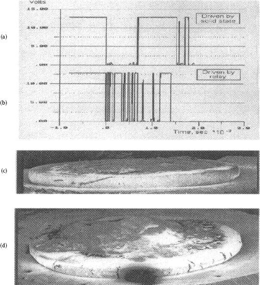
FIGURE 16.6
An illustration of transfer variation as a result of contact bounce frequency. Bounce trace (a) for contact (c) has a relatively low frequency compared to trace (b) for contact (d), but both have about the same bounce arc duration. Both silver–tin-indium oxide contacts saw the same lamp loads for 16,000 operations [31].
Another factor that influences material transfer and formation of pip and crater formation is contact activation, see Chapters 10 and 19. Witter and Polevoy showed that organic vapors given off by plastic components in the relay had a beneficial effect for preventing pip and crater formation [31]. Germer showed that as a result of contact activation by a substance such as carbon, the arc spot moves from one operation to another and pip and crater formation is prevented [60]. In addition to this it was shown by Germer et al. that contacts can be activated by non-organic materials such as minerals, silica, alumina, and others. A special silver metal oxide material that has been used for many years is AgMgO (0.3wt%)NiO(0.3wt%). The microstructure of this material is an extremely fine submicron random dispersion of oxide particles in the silver matrix. This microstructure continually produces an activated surface and as a result this small amount of oxide is effective in reducing transfer for dc switching.
From what has been discussed, it can be seen that many factors influence the transfer that results from a silver metal oxide material including circuit parameters, device parameters, and factors influencing contact activation. A material may show good transfer resistance at one level of current and high transfer at another as demonstrated above. The erosion characteristics and the sticking coefficient for anode transfer onto the cathode is important in influencing transfer build up. In testing relays with different silver–tin oxide type materials under severe bounce conditions, a material with a low arc erosion resistance formed no pip and crater type erosion but had very high anode material loss; another material with moderate erosion resistance had significant pip and crater formation under the same conditions, and yet another silver–tin oxide material with much better erosion resistance showed a low erosion rate with no pip and crater erosion [12]. Thus in this case a material with an erosion rate intermediate to two other materials, showed much more anodic transfer than materials above and below it in erosion rate. These results are not surprising considering the many factors that have been discussed that can influence transfer and pip and crater formation. For purpose of discussion and illustration let us focus on the fact that for this type of bounce erosion, the resulting short arc resulted in mainly metallic erosion. If a pip was prevented from forming on the cathode no pip and crater would form. This was a make and break application. We knew that if it had been only make erosion, pip and crater erosion would have been probable. Some of the factors that could have affected these results are as follows:
1. If the material with the high erosion rate had a low tendency for the anodic transfer material to stick onto the cathode surface and at the same time exhibited enough cathodic erosion, there would be a low probability of a pip forming.
2. Again for their material with the high erosion rate, owing to the large amount of erosion from the anode the position of the arcing will drift more from operation to operation, and that also will lower the probability for forming a pip.
3. For the medium erosion rate material, if the factors opposite to the above are true, good wetting of the anodic transfer material to the cathode and stability of the arc spot, a pip will probably form.
4. For the low erosion rate material there was a higher metal oxide content. This also decreased the anode transfer sticking efficiency and with some cathode erosion present there was no pip buildup.
5. If, for the low erosion rate material, there is some degree of activation from additives or external factors, the arc will tend to move from operation to operation as a result of the activation sites and this with even low cathode erosion rate will make pip and crater erosion a low probability. Activation can come from gases given off by the plastic components of a relay.
The above of course is only for illustrations of possible reasons for the transfer behavior. It should be kept in mind that regardless of the material, high frequency bounce will increase the probability of pip and crater formation.
The welding resistance of silver metal oxide materials is affected by the surface micro-structure and surface geometry developed and as a result of contact arcing and material transfer. There are two types of welding that should be considered, static welding and dynamic welding (see Chapter 10). Static welding involves welding which takes place with the contacts in a closed position under force. Static welding resistance relates to contact conductivity and surface resistance. Materials with lower contact resistance have a higher resistance to welding. For silver metal oxide types there is little difference among the various materials to resistance to this type of welding.
For dynamic welding, the condition of the contact surface after some switching duty determines the welding tendency. One of the largest causes of dynamic welding for dc devices is from formation of pip and crater geometry on the contact surface as discussed above. For this type of weld, the classic welding as a result of melting and solidification may or may not occur. Many times the pip and crater form mechanical latching that prevents the contacts from opening. Once pip and crater geometry is established the life of the contact is usually limited since all erosion is taking place in a limited area which increases the extent of melting and alteration of the material in that area, including oxide depletion, segregation, and surface roughness. In Chapter 10, there is a theoretical discussion of both static and dynamic welding with equations showing the relationship of maximum weld force, contact force, contact melting temperature, material hardness, switching current, constriction resistance and the total energy into the weld spot. It also has data on weld force measurements on several different materials.
In this section, some different kinds of dynamic welding will be discussed on the basis of experimentation using some model switches. By use of a special model switch that simulated NC (Normally closed) contact operation in a DC relay Chen and Witter studied contact welding characteristics of several materials under different conditions [61–63]. They found two types of dynamic welding or sticking. One was a very weak weld, cold adhesion that occurred after contacts were subjected to a switching operation that was mainly in the metallic arc state. Once the very clean arced surface had formed, this adhesion continued for a number of operations even without current present. Figure 16.7 [63] shows a switching sequence with a combination of no electrical load, resistive load, and inductive load. The resistive load promoted the adhesion by cleaning and annealing the surface and the inductive load left a thin layer of silver oxide or carbonate on the surface which reduced the adhesion. It was found that strong welds above the adhesion level strength, >35 cN, occurred infrequently. It was also found that strong welds were always associated with very short bounce or skip arcs, <50 μsec. These welds also could occur on contact make or break. For arcs with long bounce, strong welds were never seen. For very short bounce the contact gap is very small and is associated with a high concentration of arc heat and low impact closing which left more liquid metal to solidify between the contacts. Similar findings were made by Morin et al. [24] and Neuhaus et al. [64].
Considering the findings sited above on strong welds it should be kept in mind the important role contact force and over-travel of contacts on closure play in preventing contact welding. Figure 16.8 shows a typical weld strength distribution as a function of switching endurance life for a normally closed DC relay. In this case the beginning of the switching life has no strong welds but as erosion takes place and the contact over-travel decreases the conditions that favor the formation of strong welds.
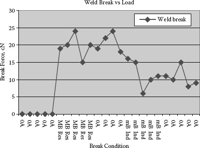
FIGURE 16.7
Weld break force with different sequential loads as follows: 0A current, 80A resistance, 0A current, 50A inductive, and 0A current.
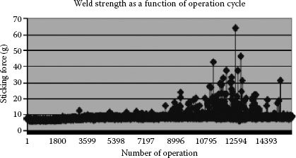
FIGURE 16.8
Typical weld strength distribution as a function of switching life [12].
There is another variation of dynamic welding that can occur if the current level is extremely high or the arcing time is very long. For example in doing some automotive DC testing of silver tin oxide composite rivets the test voltage was raised in increments to see the effect on arcing time. At 19VDC the tests showed normal erosion for about 15,000 operations and then a hard weld would occur that was completely across the face of the contacts. What was happening in these cases was the surface of the rivet was curling up from stresses created from the arcing, see Chapter 17 for curling effects. The contact gap which was marginal to start with for this voltage became too small to allow the arc to extinguish and the arc time went from less than one msec. to hundreds of msec. The movable contact in this case was a thin contact spring that could not transfer the heat out fast enough which resulted in a large portion of the contact melting and forming a large weld area on contact closing. For this type of extreme heating almost all non-refractory contact materials will form a strong bond.
Silver metal oxide materials are known to be much better than non-oxide-containing silver alloys for being resistant to dynamic welding. The characteristics of the surface layers of the materials after switching determine the welding tendency. Erk and Finke showed threshold weld currents for silver metal oxides to be over three times higher than those for silver and silver alloys [65]. One important factor to keep in mind on silver metal oxides is the effect for the metal oxide level on welding resistance. Chen and Witter show a huge benefit for higher tin oxide levels in lowering weld break force. This trend holds true for almost all silver metal oxide combinations. So here you must weigh between welding resistance and contact resistance. Another alternative is increasing the contact force which will improve both contact resistance and welding resistance. The mechanical design of the switch is also critical. For example, impactive opening will break contact welds easier than a slow pull force. Applying an opening torque can also assist in breaking a contact weld.
16.2.6 Erosion/Mechanisms/Cracking
Like other contact materials, the erosion of silver–metal oxide materials involves evaporation of metal vapors and can involve metal liquid splatter and expulsion of particulate and chunks of materials. Unlike true silver alloys such as fine silver, silver copper, and silver palladium, some silver metal oxides are susceptible to crack formation as an erosion mechanism. At higher currents, hundreds of amperes, most materials can develop surface cracking and fissures from thermal stresses from rapid heating and arc root erosion on the surface. For more ductile materials the tips of the fissure of surface cracks are rounded or blunted off. For very brittle materials the crack tips are very sharp and extend well beyond the surface into material that has not been heat affected. In the next section of this chapter under silver refractory metals the subject of brittle fracture will be discussed in more detail. Normally brittle fracture mechanisms are considered impossible in ductile materials, that is materials which have face centered cubic structures. Although silver metal oxides are in the range of about 80% silver by volume, being composite materials, weak paths made up of contiguous brittle phases can exist. For example thermal arrest lines in internally oxidized materials have been reported to cause delamination of contacts. Here the oxide particles are so concentrated that a continuous plane of particles exists which allows the crack to propagate without going through the more ductile silver phase. For silver metal oxide materials, both internally oxidized grades and powder metallurgical grades, there is potential for creation of brittle paths in the materials by somewhat different mechanisms. For both types of material extruded material are less likely to present brittle cracking problems than material made without extrusion since the metal working will tend to break up the brittle phases.
For PM grades made by press sinter and repress some additives could create brittle paths through fine grain boundaries in these types of materials. An example of this type of defect is shown in (Figure 16.9) for Li additives for silver cadmium oxide [52]. For internally oxidized silver metal oxides brittle phases can form in the grain boundaries of the materials during oxidation as a result of certain additives. For some of the post-oxidized materials these brittle compounds in the grain boundaries limit the amount of plastic deformation that can be done on the materials after oxidation. Yet some of these materials withstand arcing without any major cracking. The grains in internally oxidized silver metal oxides are much larger than the grains of the brittle press, sinter and repress metal oxides. This may account for the better resistance to cracking from arcing thermal stress. Internally oxidized materials that are made from process 2.02, see Figure 16.1, wire or strip extruded after oxidation, have no problem since the metal working destroys the continuity of the brittle phases. Another variation of internally oxidized silver metal oxides that have appeared in the 1990s are ultra-fine materials made by high-pressure oxidation, they contain dispersions of oxide particles less than 100 nm in size [66]. These materials are over one order of magnitude finer than the general silver metal oxide grades. It is worth mentioning these materials in this section on cracking since as the particles become finer the materials become more brittle from restriction of dislocation movement by the ultra-fine particles and thus more susceptible to cracking.
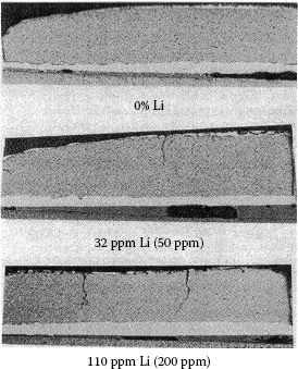
FIGURE 16.9
Examples of brittle cracks going through an Ag/CdO 10wt% CdO with different levels of lithium as an additive, lithium levels shown both after sintering and before [52].
For break erosion in devices designed to move the arc from the contact onto arc runners and arc chutes (see Chapters 14 and 15), arc mobility is a factor affecting the amount of erosion that takes place. Composite materials like silver metal oxides have lower arc mobility than pure silver and homogeneous silver alloys [67]. Little difference in arc mobility has been found among the various silver metal oxide compositions by Schroder [68,69]. He also has found that the manufacturing process has more effect than the chemistry with the internally oxidized grades showing faster arc mobility than those grades made by powder metallurgy. The effect is thought to be associated with differences in the silver grain boundaries between the two types of materials. Manhart et al. have shown that the arc running velocity is a function of contact gap and independent of metal oxide type, but that silver–tin oxides tend to begin movement at shorter gaps [70].
16.2.8 interruption Characteristics
The ability to interrupt a circuit is an important characteristic for silver metal oxide materials, especially for use in devices like contactors. The tendency for arc retention after current zero in some ac switching devices owing to alkaline impurities in some new silver–cadmium oxide materials had been seen in the 1970s [71]. Some companies making silver–cadmium oxide materials by powder metallurgy at that time were experimenting with new processes for making silver powders and as a result unintentional increases in alkaline impurities, less than 100 p.p.m., ended up in the finished silver–cadmium oxide contacts. The example illustrates how careful companies must be in insuring that production processes for making contacts are not altered without extensive electrical testing of the contacts. At the same time some companies were experimenting with lithium as an additive to silver–cadmium oxide for improving the erosion life. The ability for a device to interrupt an ac circuit, reduction of reignition voltage, after current zero can be degraded by contacts containing small amounts of elements that have low work functions and low ionization potentials (see Chapter 9). As a result of this several separate groups ran tests and published the results for the effects of retained traces of sodium, potassium, and lithium in silver–cadmium oxide [71,72,73]. In general similar results were found by all groups. Lindmayer ran tests at 350 and 700 A and at 12 and 35 kHz. His conclusion was that potassium should be kept <20 ppm and sodium and lithium <50 ppm All three of these elements had a low work function and a low ionization potential, potassium being the worst. Braumann and Schroder ran comparisons between AgCdO and AgSnO2 materials containing no alkali metals and found similar results for both, that is, good extinction properties of both materials in comparison to non-silver metal oxide materials like fine silver and silver refractory metals [67,74]. Gengenbach et al. compared interruption times and maximum arc voltage just before interruption for several types of silver–cadmium oxide and for one type of silver–tin oxide in a dc contactor at 200 A and 12 V [75]. No significant differences were found among the materials for arc interruption duration.
The contact resistance for silver metal oxide materials before switching duty is like other silver alloys dependent on the bulk resistivity, hardness of the material, surface geometry, and presence of oxide and/or corrosion films. As shown in this chapter’s section on welding, contact arcing using a resistive load, metallic arc, cleans the contact surface and besides increasing adhesion between the contact pairs will lower the resistance. This is because silver oxide is not stable over 300 C. In general the initial contact resistance variations for clean un-arced contacts among the various types of silver metal oxides differ little and the values for resistance are low.
After contacts are subjected to switching duty the surfaces change mainly as a result of reactions between the contact surface and the electrical arc. As a result of arcing silver metal oxide contacts build up a surface layer that contains a mixture of metal and slag; that is, fused metal oxide aggregates. Like erosion characteristics, the microstructure of this layer will vary as a result of many factors including contact chemical composition, contact metallurgical characteristics, and switching load. The characteristics of this layer will determine many performance aspects of the contact and in particular both contact resistance and welding resistance. If the surface layer becomes depleted of oxide material the surface will react more like fine silver contacts, that is, low electrical resistance but high tendency for dynamic welding. If, on the other hand, the oxides build up to higher concentrations the contact will be more refractory in characteristic and the contact resistance will be high but the tendency for dynamic welding will be lower. This is an over-simplification for purpose of illustration.
Silver–tin oxide generally has higher contact resistance after switching duty than silver–cadmium oxide. In previous sections of this chapter it was shown that there are a large variety of silver tin oxide materials. Both the research on processes and additives has created materials more sophisticated than the materials developed in the past. Many times combinations of additive are used to reduce resistance and improve erosion resistance. Mutzel et al. [30] tested a variety of advanced materials which were both PM and IO with additives using a DC automotive load. Figure 16.10 shows a resistance comparison of six materials after endurance. The biggest difference in results is for higher resistance as the oxide level increases. The IO material is a little higher in resistance than the PM.
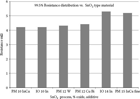
FIGURE 16.10
A comparison of contact resistance values of different silver tin oxide materials tested at 40 amperes inductive load at 13 VDC for 50,000 operations [30].
Work will continue on silver tin oxide and silver zinc oxides systems with use of additives. Significant improvements have been made for both IO and PM grades. The use of composite powders with chemical precipitation has allowed the PM grades to improve significantly in erosion to compete with IO product. More so than ever, it can be said that there is no generic type of silver metal oxide material. This means it is very important that the user understand and test the material chosen for an application.
Silver refractory metals are a special category of arcing contact materials for use in high fault current applications. These applications include residential circuit breakers, industrial breakers and high current switchgear used by utilities. A volume of silver-refractory metals are used in North America as a result of the high current level fault protection required by UL even for residential homes. It also should be noted that the requirements for fault current devices are different in different parts of the world so the material requirements also differ. The research level being done on these materials is continuing but not at the pace of work in the silver metal oxide field.
Silver refractory metals are mixtures or composite structures as opposed to true alloys since there is no or very limited solubility of the silver with the refractory metal. Since there is no alloying with the silver, the silver phase of the composite metal retains its high electrical and thermal conductivities. Since copper refractory composite metals which are discussed in the next section of this chapter are very similar in structure to silver refractory metals, points on those materials will also be made in this section. The silver refractory metal category includes combinations of silver with both the elemental refractory metals and also carbides of refractory metals. Much of the past work has been on silver tungsten, silver tungsten carbide, and some on silver molybdenum. More recently there is new work on mixtures of silver tungsten and silver tungsten carbide with additions of graphite. Some of these grades of materials are also paired with other contact material like silver graphite and silver nickel. Since these composite materials are made by different processes it is important to have a basic understanding of the technology in making choices on these types of materials.
In this section there will be a discussion of the basic manufacturing processes being used and some characteristics of those processes, metallographic methods for evaluation of the microstructure of the materials, physical material properties as related to the microstructure, and electrical performance properties. Table 16.3 lists some common compositions of W/Ag, WC/Ag, Mo/Ag, Mo/Ag, and W/Cu. Tables 24.4 and 24.8 in Chapter 24 have a more complete listing of different properties for these materials. The density, hardness, and electrical conductivity are listed as typical values, approximate mean value for several brochures and other tabulations for the various materials [2,3,4,5]. The volume percentage of the soft phase is also shown in Table 16.3 since there is a large density difference in silver, copper, and tungsten and the properties relate to volume percentage not weight percentage (see Chapter 24, Section 24.2[h]). The tungsten copper materials are for the infiltrated grades only and this will be explained in the following sections.
TABLE 16.3
Typical Refractory Metal Contact Compositions Including Hardness and Conductivity Values
Material |
Ag or Cu (wt.%) |
Ag or Cu (Vol.%) |
Hardness HV (kg mm−2) |
Conductivity (m Ω−1 mm−2) |
W/Ag-20 |
20 |
32 |
200 |
23 |
W/Ag-25 |
25 |
38 |
185 |
25 |
W/Ag-35 |
35 |
50 |
165 |
28 |
W/Ag-50 |
50 |
65 |
130 |
36 |
WC/Ag35 |
35 |
45 |
175 |
23 |
W/CAg-50 |
50 |
60 |
155 |
29 |
WCAg-60 |
60 |
69 |
145 |
32 |
Mo/Ag-35 |
35 |
34 |
155 |
24 |
Mo/Ag-50 |
50 |
49 |
140 |
29 |
W/Cu-25 |
25 |
42 |
200 |
23 |
W/Cu-50 |
50 |
68 |
125 |
29 |
Source: Adapted from G Rolland et al., Proc. 26th Int'l Conference on Electrical Contacts, 2012, pp 338–345 [1]; Chugai USA Brochure, Chugai USA Inc., Waukegan, II, 1995 [3]; American Society for Testing and Materials. ASTM Standards, Section 3, Metals Test Methods and Analytical Procedures, Vol. 03.04, 1987; K Schroder. Dissertation, TH Braunschweig, 1969.
16.3.1 Manufacturing Technology
The silver refractory metal contact materials can be made by a wide variety of powder metallurgical techniques. Since the vast majority of the materials are made by one of three basic processes, the manufacturing technology discussion will be limited to the basic differences and characteristics for these three methods. The three methods are shown in Figure 16.1, all under Process D; (1.0) press sinter repress (PRS), (2.0) liquid phase sintering (LPS), and (3.0) infiltration. More recently a fourth process, hot isostatic pressing (HIP), is being used in combination with the basic three processes to increase density. For more detailed information on general powder metallurgy techniques including, HIP, liquid phase sintering, and infiltration, “Powder Metallurgical Science” by R. German may be useful [76]. It should be understood that saying that only three general processing techniques are used does not imply that the individual processes are the same for different companies. Although two companies, for example, have processes that fit the general description for infiltration, the process steps and controls for the individual steps may vary significantly. In order to make the discussion of the three processes easier, a description of the general processing for silver tungsten will be discussed for the three techniques.
16.3.1.1 Manufacturing Technology/Press Sinter Repress (Process D 1.0)
This, like other powder metallurgical processes, starts with powder manufacturing and blending. The starting powder particle size distributions will be the main factor for determining the possible finished microstructure and also have a large effect on pressing and sintering results. For silver tungsten, one or more silver powders and tungsten powders would be selected on the basis of particle size distribution. The powders are then blended with or without additives, pressed into the contact shape, sintered, and repressed to final density. The sintering is done in the solid state, under the melting point for silver, and in a reducing atmosphere such as hydrogen. The process is normally used only for grades with higher percentages of silver, >50% by weight, since coining is not possible when the percentage of tungsten in the material is large. This process is the main process for making silver tungsten with 75% or more silver as the other two processes will not work for high levels of silver since there is not enough tungsten in the contact body to hold it together for sintering above the melting point of silver. Contacts made by this process can have considerable porosity and entrapped gases. This process has become more popular for grades that add graphite powder to silver tungsten and silver tungsten carbide. Some of these grades have a high amount of silver and also a good volume of graphite so sintering and repressing is a way to increase the density.
16.3.2 Material Technology/Extruded Material
Some of the materials that use the PSR process can also be extruded. This will produce materials with higher densities and hardness. This does not mean that the material will have better electrical performance since at least hardness does not usually correlate with things like electrical erosion resistance.
16.3.2.1 Material Technology/Liquid Phase Sintering (Process D 2.0)
For this process powder is selected and blended to the final composition desired as was done with the press–sinter–repress method. The difference with this process is that the part is sintered to density and not dependent on coining or repressing to attain a high density. This means that the parts are pressed oversize, for example 5–15% linearly, and then shrunk to final size during sintering. The sintering is done at temperatures above the melting point of the silver in a reducing atmosphere, containing H2, thus there is both a liquid and solid phase during the sintering operation. There are some important mechanisms that take place during the sintering with this process that influence the tungsten distribution which will be discussed later. The liquid-phase sintering process is composed of three stages: the first stage involves the flowing of the liquid phase into pores followed by rearrangement of the solid particles to form a denser packing; the second stage involves further densification and particle growth from liquid transport of solid phase through the liquid phase; and the third phase involves further densification by solid-state sintering of the solid phase [77,78]. Since silver and tungsten show no solubility even in the liquid state, for liquid-phase sintering to be effective in increasing the density of silver tungsten, additives, for example nickel or cobalt, are used for activation of the liquid-state sintering process [79]. Nickel is a very common additive since it has a very slight solubility in tungsten and silver in the 1000°C range, and nickel increases the self-diffusivity of tungsten by two orders of magnitude [80].
The liquid-phase sintering process can produce very high-density parts, 99%, for some silver or copper refractory systems. For metal carbides it is more difficult to obtain high-density parts with this process; therefore the process is limited in application. Some noteworthy characteristics of this process are as follows:
1. Additives for sintering are normally utilized in order to obtain density. Most additives have an effect on the conductivity of the tungsten phase. Nickel in the same composition range of these additives lowers the tungsten phase conductivity of heavy metals about 30%. This calculated out to be about a 10% decrease in conductivity for a 50 wt.% Ag and W composite that is about what is seen for composites with and without the Ni addition [81] should be noted that nickel does not decrease the conductivity of the silver phase of silver tungsten since it is not soluble in silver.
2. For the CuW system the use of additives not only lowers the conductivity of the tungsten phase but also lowers the copper phase conductivity, since copper forms a solid solution with nickel. Published data for 50 wt.% Cu/W show a reduction of 30% for liquid-phase sintered versus infiltrated grades without additives [81].
3. The first stage of liquid-phase sintering as described above involves the tungsten particle consolidation through lowering of surface free energy with the liquid phase. This phase of sintering has a major effect in increasing the contiguity of the tungsten particles, and it will be shown later in this section that, as the contiguity increases, the resistance of the material to crack propagation decreases.
This process requires less labor than the infiltration process that follows but the material toughness must be controlled to insure that the material resists cracking from the thermal shock of arc erosion.
16.3.2.2 Material Technology/Press Sinter Infiltration (Process D 3.0)
The infiltration process for making silver–tungsten material differs from the liquid-phase sintering process in that attainment of density is not dependent on shrinkage or consolidation of a pressed compact, but on filling the pores of a sintered tungsten skeleton with molten silver. The process basically consists of pressing a porous tungsten compact that contains a little silver or none at all, sintering the compact to weld the tungsten particles together, and then placing the tungsten skeleton in contact with silver and heating the combination in a reducing atmosphere to a temperature above the melting point of silver. The pores in the tungsten skeleton then suck the molten silver into them. Additives are not required as the process requires minimal tungsten sintering to attain density. There are many variations of this process both with and without additives and with different blending, pressing, sintering, and infiltration techniques. The strength of the tungsten skeleton can vary considerably with processing: for example, variations occur in the activation additives for sintering, sintering time and temperature, the starting powder mix, and both particle size and amount of silver in the powder blend. Some noteworthy characteristics of this process are as follows:
1. Good control of the infiltration process is required to insure a uniform and porous free contact structure. Several factors can cause sections of the tungsten skeleton to be void of the filler metal, such as the furnacing technique utilized and the matching of the silver weight needed to fill the tungsten skeleton. Too much silver may produce excess silver layers on the contact surface and too little will leave voids in the contact body. Metallography on cross sections of the contact and or fractures of samples can test for the quality of infiltration.
2. As a result of the sintering step for this process in which the refractory particles are welded together before the liquid phase is added, refractory particle alignment is prevented and therefore product made by the process has significantly lower contiguity of the refractory phase. This is a good property of this process which will be discussed later in the section.
3. The strength of the refractory skeleton can be varied significantly with processing and it, in turn, can affect performance results. This variable is difficult to check as an incoming property so controls in the manufacturing should monitor this property, for example checking for the extent of shrinkage (normally very small) that takes place during the sintering step.
16.3.3 Metallurgical/Metallographic Methods
The following sections relating microstructure to material properties for tungsten–silver also in principle will relate to tungsten copper, tungsten carbide–silver and other composite refractory metal systems. Since the metallographic structure plays a large role in electrical performance and metallographic preparation is unique for these materials, this section on metallographic techniques for preparation and measurements is included.
16.3.3.1 Metallurgical/Metallographic Methods/Preparation
This procedure is for tungsten–silver, but can be used for tungsten–copper and tungsten carbides–silver grades. Hand polishing of tungsten–silver alloys is difficult, especially in the case of very fine dispersions of silver and tungsten. The main problem which must be avoided is the development of relief between the hard phase and soft silver. If cloths with heavy nap are utilized the polishing grit erodes the silver at a higher rate than the tungsten. As the relief gets large the tungsten phase tends to smear over the silver phase and cover up porosity and grain structure detail. In order to avoid this, use of a no nap cloth, such as silk or some other commercial no nap cloth, is recommended, especially for the last stages of polishing. A good combination that works is the use of 0.25 alpha and 0.05 beta Al2O3 as the last two polishing stages. There may be some scratches with this technique but the structure will not have a distorted layer covering up true structure.
In order to see the tungsten grain boundaries an etchant must be used. Both modified and standard Murakami’s reagent as listed in the Metals Handbook is too active [82]. Also, the ratio of K3Fe(CN)6/Na(OH) is found to be important for attainment of preferential grain boundary etching versus total grain etching, see Figure 16.11. A dilution of 50/1 of the standard strength, a ratio of 8/1, and an etching time of 15–25 seconds has been found to provide good results [83]. The formulation is given below. The undiluted reagent over-etches the tungsten phase and makes rendition of the grain boundaries more difficult:
Na(OH) (g) |
K3Fe(CN)6 (g) |
H2O (ml) |
0.04 |
0.3 |
100 |
16.3.3.2 Metallurgical/Metallography/Quantitative Analysis
Currently there are many options in both software and hardware for doing image analysis. As long as some color or gray level exists between phases the systems can give you a multitude of statistics regarding size and distributions of the phases. This section will not cover the subject of modern image analysis, but will cover some fundamental formulas that have been used for analyzing composite materials. Most modern image analysis equipment should be able to measure the parameters which will be discussed.
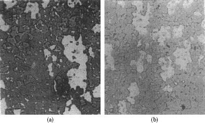
FIGURE 16.11
A comparison of polished tungsten silver etched with (a) modified Murakami’s reagent and (b) diluted 8/1 Murakami’s reagent [83].
A very commonly used composite material metallographic parameter that can be measured even by hand is λ, the mean phase intercept size. This is defined by Underwood [84] as follows:
(16.3) |
where is the volume fraction of the phase you want to measure and refers to the number of areas of that phase intercepted per unit length.
Figure 16.12 illustrates the measurement of λ for both silver as a phase and tungsten as a grain. If you know the composition, you can calculate the volume fractions and use that number to get a rough idea of the λ value. Since grain size and phase size distributions are often widely varying throughout silver refractory contacts, accuracy depends on sampling technique and the number of measurements. Automatic systems will calculate the volume fraction of the phase of interest for each area measured.
The mean intercept technique provides a relative easy size measurement technique for comparing phases, grains, and particles in silver refractory metals, copper refractory metals, and even silver metal oxides. Below an example is provided for measuring tungsten grain size using the simulated drawing of a tungsten–silver microstructure in Figure 16.12.
Example: Measure the mean grain size of the tungsten particles, dark phase, in Figure 16.12 using Equation 16.3. . The volume fraction of a phase is normally known from the chemistry or it can be calculated from the cross section using other quantitative techniques: in this case .
Another important metallographic measurement that can be made to silver and copper refractory metals is contiguity, C. The property of contiguity is defined by Gurland [85] as the ratio of grain boundary surface of a phase with itself to the total surface of that phase. The following formula, derived by Stjernberg [86] is convenient to use, and has been set up for W contiguity of AgW:
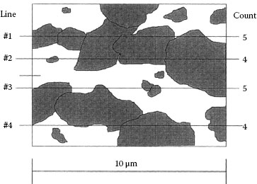
FIGURE 16.12
Illustration of the measurement of λw, mean W particle size, for a W/Ag 60 vol.%W composite material.
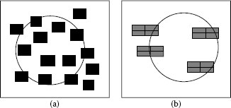
FIGURE 16.13
Illustration of contiguity for (a) particles having 0% contiguity and (b) particles having 50% contiguity.
(16.4) |
The above formula allows contiguity to be measured without needing to know the size of any particle of the phase. A straight line or, better, a full circular line, can be used to count the particles intercepted, NWG, tungsten grains and NAg, silver phase areas with the line. See Figure 16.13 for examples of measurement. Figure 16.13a is for a sample with 0% contiguity for the tungsten grains and Figure 16.13b has 50% contiguity for the tungsten grains. For the illustration a small sampling rate is used which can cause some error; it is best to use a particle count of 50 or more grains.
The contiguity parameter is mainly useful for the silver and copper refractory metal systems of contacts; it allows measurement of how continuous a phase or grain structure is with itself.
Example: Measure the contiguity of the particles in Figure 16.13 using Equation 16.4. Case a. Ndg = intercepts dark grains = 7, NLp = intercepts light phase = 7Cdg = (7–7)/7 = 0 Case b. Ndg = 8, NLp = 4, Cdg = (8 – 4)/8 = 0.5.
16.3.4 Metallurgical/Structure/Strength and Toughness
For composite electrical arcing contacts, metallurgical structure along with chemical composition determines the performance capability of the contact. Metallurgical parameters like tensile strength, shear strength, fracture toughness, and hardness are useful for composite materials used as structural components or parts for mechanical wear. For the life of electrical contacts the interest is for electrical arc erosion resistance, contact resistance, welding resistance, material transfer and other arc-related wear phenomenon. The silver and copper refractory metal contact materials, as a result of the refractory metal content, have in general a high resistance to electrical erosion compared to other types of contact materials. As a result of this they are normally used in applications where they must switch high fault currents, thousands of amperes, and are subjected to high current density arcs and thermal stress. No simple direct relationship of mechanical properties like tensile strength or hardness to arc erosion wear or resistance has been found for composite contact materials. This is the result of the many parameters influencing testing results, both in terms of the material (structural, physical, and chemical); and electrical testing (contact size, current level, chamber, device, etc.) (see Chapter 10).
An important distinction of refractory metal composites compared to most metal alloys is that they are relatively more hard and brittle owing to their content of high melting refractory metals. An important attribute to measure on brittle materials is toughness which is the resistance the material has to crack propagation. Although the high melting point refractory metal component of these composites give them good arc erosion and welding resistance, they also lower the cracking resistance of these materials. Table 16.4 is shown to help illustrate the relationship of material toughness to three well know materials and also material strength and hardness.
The electrical erosion process for contact materials involves arc reactions with the contact surface that result in material melting, vaporization, ionization, materials transfer and rapid heating and cooling. The melting, re-solidification, rapid expansion on heating follow by cooling all leave residual stresses in the material. Most of the composite refractory metals are brittle and the degree varies depending on the composition, phase interface boundaries and particle size distributions. Depending on the degree of brittleness and the amount of stress generated from the electrical cycling small cracks can be generated that contribute to the erosion or large cracks can form that penetrate deep into the material. An important factor that must be considered in predicting electrical life of composite refractory metals is an understanding of the relationship of material structure and cracking resistance, toughness.
In the last section of this chapter it was shown how to measure metallographic parameters of the structure of composite refractory metal systems. In order to better understand and predict potential cracking problems with composite refractory metal materials like tungsten silver Witter and Warke [87] conducted a study on a matrix of tungsten silver materials that differed in composition and particle size distribution of the of the tungsten and silver phases. The matrix is shown in Figure 16.14. Besides having materials of different composition and particle size distribution the matrix includes a material made by a different process, infiltration.
In order to measure the brittleness of the material and potential for cracking a fracture mechanics technique was used to measure toughness of the material in terms of GIC the critical energy release rate. This is the energy required to extend an existing defect or crack in the material under plain strain as shown for the following formula:
TABLE 16.4
Relative Relationship of Mechanical Parameters
Material |
Strength |
Hardness |
Toughness |
Copper |
Low |
Low |
High |
Tool steel |
High |
High |
Medium |
Ceramic |
High |
Very high |
Low |
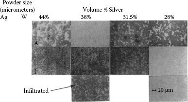
FIGURE 16.14
Microstructure of three coarse and three fine liquid phase sintered tungsten silver materials and one infiltrated material [87]. All materials were 97% of theoretical density or better.
(16.5) |
where Pc is the critical load for crack growth, tn is the material thickness at the crack area, c is compliance (deflection per unit load), and a is crack length [88]. For more details on the actual technique used and apparatus please see reference [87] and for more information on fracture mechanic techniques see references [88,89]. In Figure 16.15 the results of the GIC measurements on the various materials are compared to results of transverse rupture strength (TRS) measurements and Vickers hardness measurements made on the same matrix of material. For the hardness measurements it shows a higher hardness for the finer materials and a higher hardness with an increase in tungsten content but there is little difference for infiltrated and liquid face sintered materials. The TRS measurements show slightly higher strength for finer materials but little difference with tungsten content. The GI, critical energy release rate measurements show a clear large distinction for both phase size distribution and volume percentage of tungsten. It also shows a large increase in toughness for the infiltrated product compared to the liquid phase sintered product of the same composition. Arc erosion testing conducted at 8,000 amperes on the same matrix correlated well for prediction of cracking and showed the 69% tungsten fine grained material to have severe cracking.
Further work was done on this project to see if the measured metallographic parameters and the volume fraction parameters could be used to relate to the relative toughness of the materials in the matrix. A crack in one of the contacts was sectioned and studied and is shown in Figure 16.16. The cracks in these materials will try and follow the weakest phase interface in the structure. In this case there are tungsten to silver interfaces, silver to silver grain boundary interfaces, and tungsten to tungsten grain boundaries. The tungsten to tungsten grain boundaries are by far the weakest. So a crack that starts out in a fractured tungsten grain boundary will try to continue to grow by following and fracturing more tungsten grain boundaries which in this case is the path of least resistance. The obstacles to this path are the silver phase areas that separate the tungsten grain aggregates. So both the volume percent of silver and also the coarseness of the silver phase areas have an effect on the amount of energy it takes to either rupture and go through them or go around them. The other important factor is the contiguity of the tungsten phase as discussed in the metallographic section. The more contiguous the tungsten phase is the easier it is to go around the silver phase. From empirical work, Witter and Warke developed Equation 16.6 for the silver tungsten system relating metallographic and phase volume fraction data to fracture toughness:
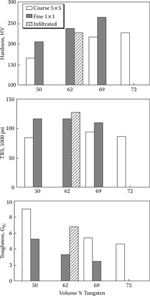
FIGURE 16.15
A comparison of strength, hardness, and toughness as a fundction of composition and phase-size distribution of tungsten-silver materials, including six liquid-phase sintered materials and one infiltrated material [83].
(16.6) |
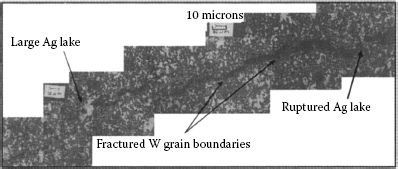
FIGURE 16.16
Cross section of a brittle fracture in an arc-eroded liquid-phase sintered sungsten–silver contact. The crack is perpendicular to the contact face.
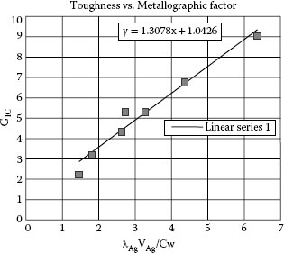
FIGURE 16.17
For tungsten-silver contacts: a correlation of the factor, with fracture toughness [83].
Where λAg is the size of the silver phase areas, VAg is the volume fraction of the silver phase, and Cw is the contiguity of the tungsten phase and k and € are constants for the material system being tested. Figure 16.17 shows a plot of the data using this equation and constants.
16.3.5 Electrical Properties (EP)
Above the relationship of mechanical, compositional, and microstructural properties of refractory metal contacts was discussed mainly with data on the basis of the tungsten–silver system. It was seen that the relationships are complex and that the mechanical properties are significantly affected by the composition, particle size distributions of the phases, phase and grain interface properties and distribution, and method of fabrication. In this section if it will be seen that although the erosion properties of these materials are affected by the same structural variables as the mechanical properties, clear quantitative relationships do not exist between the mechanical properties and the erosion behavior of these types of materials. Another difficulty in studying the electrical erosion properties of these materials is that although a significant amount of work has been published on erosion of refractory metal electrical contacts, it is difficult to make comparisons since the results are also influenced by numerous device and testing variables as discussed in Chapter 10. In 1986 Slade [90] published a review of prior work for erosion of both silver and copper refractory metals which provides references to most of the significant work done at that time.
As mentioned earlier composite refractory metal contacts are mainly used in high current devices that provide fault current protection. Most of these materials are not suited for lower current repetitive switching devices since they develop high resistant films as a result of switching low and medium currents. This subject will be discussed in detail in a section later in this chapter. As a result of this the main interest in these materials is for switching currents of about 1000 A or more. It is generally agreed among researchers that at these higher currents the composite refractory metals offer superior erosion resistance compared to other silver-based alloys, including silver metal oxides. For electrical erosion the discussion will therefore be based on examples and work which involve only higher currents. This does not imply that these materials are not switched at low currents in some device applications but only that the device life is normally limited as a result of contact resistance. The discussion in this section will start with a discussion applicable to all of the composite refractory metal types looking at the correlation of erosion with mechanical and microstructural properties. The discussion will then be divided between specific work on the silver-based and copper-based materials. The copper-based materials are limited to devices offering oxidation protection such as oil interrupters, SF6 devices, and vacuum switches.
16.3.5.1 EP/Arc Erosion/Microstructure and Properties
In Section 16.3.3, the relationship was discussed of mechanical properties and microstructure for composite refractory metal contacts using a matrix of tungsten–silver materials for demonstrating examples of various relationships. The same material matrix will now be used for discussing the relationship of mechanical and microstructural properties to arc erosion characteristics of these materials.
The same materials that were mechanically tested were subjected to arc erosion testing. The arc erosion testing was performed on 10.2 mm diameter by 2.0 mm thick disks brazed onto a copper carrier. The current source was a capacitor bank discharged through a transformer yielding a current of 8000 amperes peak of 60 Hz dc with a duration of 0.5 cycles. With a fixed contact gap of 3.2 mm, the arc was triggered by discharging the current through a very fine pure silver wire, 0.025 mm in diameter, placed between the contacts. Each contact pair was subjected to ten half-cycles of arcing. It should be noted that this testing involved no contact closure, so there was no contact bounce and no splatter from closing contacts coming together under arcing conditions, and also since the gap is fixed, the contacts do not see normal interruption conditions of a transition from a molten bridge to a metallic arc followed by a gaseous arc.
The erosion was measured in terms of total erosion from the contact pair in terms of volume of material lost versus weight loss that allows erosion comparisons for different material compositions. At high current levels the erosion process involves material evaporation, molten metal droplets being spattered from the contact surface, and chunks of composite material being broken off by thermal stress and oxidation and being ejected by the arc forces from the contact surface. Distortion of the contact can also take place without volume loss for softer materials, resulting in the contact material near the face surface increasing in diameter, mushrooming, compared to cooler layers of material under the surface. The materials picked for this study all had relatively high tungsten contents and thus were more prone to brittle behavior rather than distortion.
The results of the fault current level erosion versus mechanical properties for the material matrix are shown in Figure 16.18. The transverse rupture strength versus erosion shows very little correlation. The hardness plot versus erosion shows some trend with high hardness materials having high erosion rates. This would relate to brittleness of harder materials. The toughness plot versus erosion rate shows that materials with high toughness have much better erosion rates than those with low toughness readings. This clearly shows that for composite refractory metals there is a big influence in the erosion rate from thermal shock damage which results in cracking the surface and breaking off particles. The factor visible in these plots is the result of the infiltrated material compared to the liquid phase sintered materials. This material is a medium fine material and had the lowest erosion rate of all the materials. As a result of the low tungsten contiguity this material has a high resistance to cracking under the stress created by the arcing. This is a very significant factor for consideration of this manufacturing process.

FIGURE 16.18
The arc erosion resistance of tungsten–silver materials as functions of mechanical properties, including 11 liquid-phase sintered materials and one infiltrated grade which is encircled [83].
16.3.5.2 EP/Arc Erosion/Silver Refractory
Walczuk tested tungsten-silver materials made to two compositions 50/50 and 65/35 by wt% W/Ag made by similar infiltration processes by four different suppliers [91]. He tested at 4 kA and 8 kA and found the erosion to be at least doubled at 8 kA. There were significant differences among the materials from the different sources despite the fact that similar processes were utilized. All of the 65/35 materials had more anodic than cathodic erosion (see Chapter 10 for definition), up to five times the amount. Walczuk attributed the high anodic erosion to the effects of the plasma jet of the cathode on the anode at the high currents. The 50/50 materials were mixed with regard to erosion being predominantly anodic or cathodic and were in general lower in total erosion than the 65/35 materials. No explanation was given but the data suggests some influence from the manufacturing method. SEM photographs of fractures for two of the materials studied show significant amounts of plastic deformation, indicating that these materials were much more ductile than the matrix of materials studied in the previous section. This would suggest more erosion from evaporation and droplet expulsion than brittle chunk expulsion.
Leung and Kim compared the erosion characteristics of infiltrated grades of Ag/W, AgWC, and Ag/Mo all with 50% by volume silver [92]. The materials were 98.5% dense or better. The testing of 4.7 mm diameter contacts was at 1600 A r.m.s. at 220 V ac with a long arc duration of two cycles at 60 Hz. The volume erosion rate differences found among the three types of materials were within a total spread of 7%. Although the erosion rates were very close significant differences were reported for the erosion mechanisms. The tungsten–silver eroded surface was reported to have many tungsten-rich cones and shows erosion of silver on the surface from capillaries or fissures which go below the surface followed by erosion of the tungsten-rich surface. The WC/Ag showed more even erosion with more composite chunk ejection from the surface as a result of the very weak WC/WC bonding and poor wetting of Ag to WC. The lower conductivity of the WC/Ag material also was thought to increase loss of Ag from the surface evaporation. The Mo/Ag showed an eroded surface with segregated silver and molybdenum droplets. There was less evidence of cracking but more evidence of silver being ejected as droplets as a result of poor wetting with the molybdenum.
Lindmayer and Roth also made comparisons of several types of tungsten–silver, both liquid-phase sintered and infiltrated, and also several types of tungsten carbide–silver, at currents of 350, 700, and 1000 A, and found that the erosion rates overlapped for the tungsten versus the tungsten carbide grades and that the tungsten–silver grades had a very wide spread at the 1000 A level [93]. They also ran tests on different sizes of tungsten–silver contacts and showed that at low currents the erosion increased linearly with current independent of size and, at higher current levels, depending on the size of the contact, the rate of erosion as a function of current level increases significantly. This bend in the erosion–current plot is stated to take place when the arc reacts with the major part of the surface area [94]. The bend point occurs at higher currents as the contact becomes larger.
Besides the refractory metal and silver, the chemistry of the composite materials can vary for various additives utilized during the material processing. Two commonly used additives for these types of materials are nickel and cobalt. Witter found that increasing the nickel content of liquid-phase sintered tungsten–silver increased the erosion rate significantly [95]. Kabayama et al. found the same thing true for cobalt additions to tungsten–silver [96]. Walczuk investigated the additions of 0.5, 1, 2, and 5% rhenium by wt. to tungsten–silver 50/50 [97]. He found that the erosion rate decreased for additions up to 2% and then increased. There is no explanation of the reason why the erosion rate drops and then increases, but the porosity level of the material increased as the rhenium level increased, which indicates an effect on the sintered structure.
16.3.5.3 EP/Graphite Additions to Silver Tungsten and Silver Tungsten Carbide
In some molded case circuit breaker, MCCB, applications asymmetrical contacts have been used. On the movable side a high erosion resistant material like silver tungsten carbide could be used and on the stationary side a low electrical resistance material like silver graphite may be used. Since the erosion rate for silver graphite is high, work is being done for replacing it with a material with more erosion resistance. Leung et al. [98] conducted comparisons of AgWC with graphite additions of 3% to AgC 5% made by different processes. Earlier work had been done by Allen et al. [99] on similar material with graphite additions that included both silver tungsten and silver tungsten carbide. The new results showed better erosion life with the AgWC + graphite made by the same process, press sinter repress. The anti-welding was not quite as good as AgC but the resistance to re-ignition was better. For these types of materials it was found that increasing the graphite amount increases the erosion rate. Decreasing the graphite particle size also increases the erosion rate a little but also improves the welding resistance. The materials in this work were made by press, sinter, and repress. The sintering must be done in the solid state. Some of these materials can be made by sintering and extrusion as an alternate process. The processing may be difficult because of the brittle nature of this type of material.
16.3.5.4 EP/Copper Refractory Metals
The structure of tungsten–copper composite contacts is very similar to tungsten–silver, a soft, ductile, high-conductivity metal phase mixed with a tungsten phase. The main difference between the two materials is that the oxides of silver are not stable at high temperatures and therefore is oxide free after arcing, as opposed to copper, which forms stable oxides at high temperatures. As a result, tungsten–copper can only be used in applications where it is protected from oxidation. These devices include, oil, SF6, and vacuum interrupters, all of which are somewhat different and involve specialized technology. Some references for these types of devices are, “Circuit Interruption, Theory and Design,” by Browne, and a review of material development for vacuum interrupters by Slade [100–101]. Another difference of tungsten–copper alloys from tungsten–silver is that some of the materials used as minor additives for activation and improving wetting characteristics of tungsten are not soluble in silver but are soluble in copper, and therefore significantly reduce the electrical conductivity of the copper. Figure 16.19 shows the effect of minor nickel additions on the conductivity of tungsten copper [81].
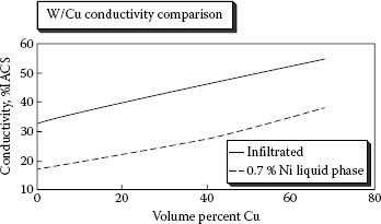
FIGURE 16.19
A comparison of conductivity for Cu/W materials with and without Ni additives.
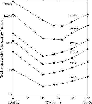
FIGURE 16.20
A comparison of erosion rate for various tungsten–copper compositions at different current levels in oil [104].
Several groups of researchers have investigated the erosion characteristics of tungsten–copper over the total composition range from pure copper to pure tungsten [102,103,104]. Both Haufe and Abdel-Asis show similar erosion rates in air and oil for tungsten–copper except at the copper-rich range where Haufe shows higher erosion in oil. In comparing erosion rate as a function of tungsten content, all three research groups show agreement that tungsten–copper composite mixtures have lower erosion rates than either pure copper or pure tungsten. Differences exist among the groups as to the compositions showing the lowest erosion rate, but this is expected since many differences exist, that is, contact size, processing, current density, and more. Zessack showed a linear relationship of erosion as a function of the number of operations for both 34% and 45% Cu by weight tungsten–copper. Figure 16.20 shows erosion rate results as a function of tungsten content in terms of volume loss per operation for switching in oil at six different current levels [104]. The 25 mm by 45 mm contacts were made by a laboratory non-infiltration process which produced a structure low in porosity and little contiguity of the tungsten particles. For this case the erosion results show that the optimum low erosion composition shifts to higher tungsten compositions as the current is raised. Zessack describes the erosion mechanism as taking place in three stages: stage 1 is mainly evaporation of copper from the surface, stage 2 involves the tungsten-rich surface with sub-layers of copper where the tungsten melts and erodes through evaporation and sputtering, and in stage 3 a stabilized surface is created with both copper and tungsten erosion.
Labrenz shows a comparison of erosion rates for tungsten–copper contacts in both oil and SF6 breakers for currents up to 7.2 kA, see Figure 16.21 [105]. The erosion rate is much less in SF6 than oil by a factor of 2 to 7 depending on the current level. Also, included in Figure 16.21 is a comparison of erosion for ring-shaped electrodes in SF6 for which the arc is magnetically forced to move around the circumference of the ring. By the rotary movement of the arc the erosion is further reduced by a factor of 3–7 depending on current level. Tungsten–copper ring contacts are stated to have about 10 times the erosion life of copper ring type contacts. Labrenz explains the erosion mechanism in SF6 to be similar to oil for tungsten–copper with high copper evaporation occurring in early life followed by more stable lower erosion rates after several hundred operations.
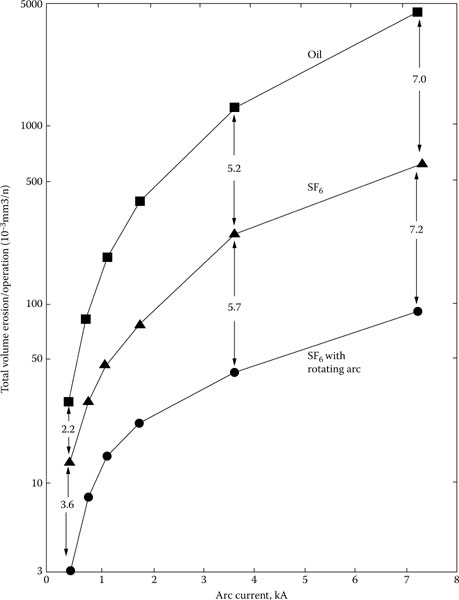
FIGURE 16.21
A comparison of tungsten–copper erosion in oil, SF6, and SF6 with a rotating arc ring [105].
Kaminski describes erosion of tungsten–copper and other contact nozzle electrode materials in SF6 breakers in which the contacts are subjected to normal plasma erosion, heating and plasma jets, and also to mechanical erosion by high-pressure gas flow [106]. In this device the arc is moved off the contact electrodes in less than 2 ms by an SF6 blast for currents below 10 kA for all materials tested. At higher currents a stable arc forms between the contacts which remains in place in spite of strong gas flow. The current level at which stable, immobile, arcs form varies with materials and is higher for homogeneous materials like copper and tungsten than heterogeneous materials like tungsten–copper [107]. The levels at which stable arcs formed were about 12 kA for the 81/19 wt.% tungsten–copper and 20 kA for pure copper and tungsten electrodes. Data taken from Kaminski’s work was used to form Figure 16.22. It shows tungsten to have a slightly lower erosion than tungsten–copper at 10 kA, but the reverse to be true at 30 kA where both tungsten and tungsten–copper form stable arcs. In oil breakers even at 0.4 kA Figure 16.20, the tungsten–copper material showed lower erosion than tungsten contacts. The difference here is that the arc retention time on the tungsten or tungsten–copper contacts at 10 kA is about 2 ms compared to 10 ms for the oil breaker testing, thus less temperature effect on the contact surface. At 30 kA the arc retention time is long on the contacts and the tungsten–copper erodes at a lower rate than the tungsten as a result of surface cooling effects of evaporating copper and higher thermal conductivity of the composite structure. These examples illustrate that besides current level, arc duration is another important consideration when comparing materials having different thermal properties and melting points. Kaminski conducted another interesting material erosion experiment with the SF6 nozzle type breaker [106]. A comparison was made for erosion under SF6 for infiltrated tungsten–copper 81/19 material versus tungsten heavy metal material, W/Ni/Cu/Fe wt.% 94/4/2/1, both with and without high-force SF6 flow. The test was conducted at 29 kA which results in stable arcs despite gas flow. The results in Figure 16.22b show that the SF6 blast has almost no effect on the tungsten–copper but a large effect on the heavy metal. Another surprising result is that the heavy metal has only a slightly higher erosion rate than the tungsten–copper under the no-blast condition.
In order to discuss this result, first, the structure of heavy metal must be explained. Basically it consists of a tungsten phase and a binding phase which cements the tungsten particles together. The tungsten particles are normally much larger in size and more rounded in shape than what you would find in tungsten–copper as a result of significant grain growth through Oswald ripening during liquid-phase sintering [20]. The tungsten phase of such alloys normally has low contiguity of tungsten grains although the volume percent of tungsten in the structure is high. The binding phase is lower melting than the tungsten phase but slightly higher than the melting point of copper, and therefore in this respect is similar to tungsten–copper. Another significant difference for this material from tungsten–copper is that the nickel and iron alloy with the copper and tungsten and thus the composite heavy metal material has a very low conductivity, <10% of copper and about one-fifth the conductivity of the infiltrated tungsten–copper.
In this example, it can be seen that high temperatures from the arc will penetrate deeper into the heavy metal than for the tungsten–copper since the heavy metal has very low conductivity and also a lower percentage of lower boiling point material for evaporating and cooling the contact surface. When the binding phase becomes molten the tungsten particles will be worn away by the gas blast since the tungsten particles have little contiguity. For the tungsten–copper material, layers just under the surface remain cooler and only molten copper right at the surface can be removed by the gas blast, since the tungsten on the surface remains bonded to the sub-layers. Also, the tungsten at the surface protects molten copper just below the surface from being wiped away by gas blast.

FIGURE 16.22
(a) Erosion of tungsten–copper, tungsten, and copper ln SF6 nozzle breaker at three current levels and (b) erosion in the same breaker with and without a gas blast [106].
The relatively low erosion rate of the heavy metal, only slightly higher than the tungsten–copper, under the no-flow condition for this testing is more difficult to understand. As a result of the very low conductivity, you would think that at 30 kA current even without the gas blast the arc would splatter molten particles from the surface. Possibly the wetting of the cemented phase to tungsten phase is strong enough to resist the forces associated with arcing. The heavy metal material is also quite ductile compared to copper-tungsten materials in the same tungsten composition range, so erosion by brittle fracturing of small chunks will be low.
From the above discussion, it can be seen that the erosion process involves many factors for composite refractory contacts. In trying to summarize the various factors discussed above the following can be stated.
As the result of arc erosion on switching, the surface of the material changes. In most cases cited above the researchers for composite refractory metal materials state that an equilibrium type surface is established after some hundred arcing operations which yield fairly linear erosion as a function of switching life. The characteristics of this surface depend on both the characteristics of the subsurface from which the surface forms and the ambient conditions existing around the surface during arcing. There are many ambient variables, such as current level, type of electrical load, current density, oxidation protection, current duration, cathode jets, external gas blasts, magnetic forces, and gap size that influence the kind of surface that forms. Some of the material variables affecting the equilibrium surface are types of refractory, refractory content, particle size distribution, contiguity of particles, minor additives, material toughness, and processing.
As a new composite refractory metal contact is arced, the lower melting phase evaporates from the surface. As a result, the refractory content of the surface increases with the formation of a mixture of complex oxides of the refractory metal, slag containing both metal components, and molten metal of both the refractory phase and the lower melting phase. In the above examples we see that if the sub-layers have brittle interfaces, WC/WC bonds for example, chunk erosion is dominant and the surface layer contain little molten metal. If the bulk material is more ductile, like tungsten–silver, the surface layer is shown to become refractory rich with molten tungsten cones, tungsten oxides, and silver islands with many fissures going deep into the material. The erosion in this case is both from the surface and from evaporation of silver from the fissures. If the materials are very coarse, the layer may contain large areas of silver or copper, and droplet type erosion and evaporation may dominate erosion rate. As the bulk material becomes finer, chunk erosion will become more dominant. The oxide-rich surface layers only have small silver islands and most silver erosion is through the fissures in the surface. The brittle nature of the surface with the fissures results in small particles breaking off during erosion. A main point for understanding erosion of these materials is that for composite materials the surface characteristics of new contact surfaces only control erosion characteristics for early contact life and that stable erosion is dependent on an equilibrium surface that is established later in contact life.
Some general conclusions on erosion of composite refractory materials are as follows:
1. The composite refractory metals generally are found to have lower erosion rates than either of the components of which they are composed.
2. For the low refractory content range of these materials the erosion rate increases as the low melting phase increases and becomes less protected by the refractory material from erosion through expulsion of metal droplets and evaporation.
3. For high refractory content composite materials the metallographic property of contiguity of the refractory phase seems to correlate with erosion rate, thus as the brittle paths through the material become more continuous the erosion rate increases as pieces break off from thermal stress of the arc. Both increasing the refractory content and decreasing the refractory grain size increase contiguity.
4. The optimum refractory content for lowest erosion depends on many factors including current level, current duration, contact size, material structure and properties.
5. Most of the mechanical properties of these materials do not have a clear correlation with erosion properties, but materials with lower toughness, especially for high refractory contacts, seem to have higher erosion rates than high toughness materials.
6. The erosion rate is significantly affected by the relationship of the contact size to the current level and arc size. The erosion rate as a function of current rises steeply above the current level where the arc has reacted with the total contact face area.
7. A comparison of the relative erosion rates of different composite refractory metal systems by composition is difficult since processing of the materials has a major impact on properties.
8. Under dc the degree of anodic or cathodic erosion for contact materials depends on many factors such as gap, circuit voltage, current level and contact opening speed.
9. Erosion of tungsten–copper in air and oil seems to be similar for most ranges of composition.
10. High-pressure gas blasts associated with some high-current interruption devices have no significant detrimental erosion effect on tungsten–copper contacts but are detrimental to heavy metal materials that have little tungsten contiguity.
16.3.5.6 EP/Composite Refractory Materials/Contact Resistance
Even though silver-based refractory composites have very good erosion resistance properties, the use of these materials in switching devices is limited as a result of contact resistance problems associated with oxides that form on the surfaces of the contacts from arcing in air. As a result, these materials are mainly utilized in devices that need arc erosion resistance for interrupting high-current faults but do not require tens of thousands of switching duty endurance operations. These types of devices, circuit-breakers and interrupters, are normally designed to have high contact pressures and/or good mechanical wipe to help lower the resistance effects of the oxides. The instability of contact resistance with these materials has been recognized for a long period of time and has been the subject of many research projects [92,108,109,110,111]. The main goal of this type of research has been to better understand the mechanisms causing the contact resistance instability and to find ways to improve the resistance characteristics of these materials without detracting from the erosion and anti-welding characteristics of the materials.
The contact resistance that develops and is measured for arced silver refractory contacts depends both on the current level that is being switched and on the current used for measuring the resistance [93]. Lindmayer and Roth tested a variety of tungsten–silver and tungsten carbide–silver contacts at different current levels, 60–1800 A, and for several different contact sizes. At low arc currents, below 200 A, their data shows little relationship between contact size and contact resistance. Figure 16.23 is a plot of data taken from the data in the Lindmayer and Roth paper [93]. This Figure shows resistance versus switching current level for four contact sizes. It can be seen that as the contacts become larger for a fixed current the resistance increases and that also as the current level increases for a fixed contact size the resistance drops. Lindmayer and Roth have a qualitative model for explaining this relationship. After arcing they found a difference between the center and outer areas of the contacts. The center crater and splash ring surrounding the crater area they found to have metallic conduction when probed for voltage drop, and the area outside the ring was found to be mainly nonmetallic. As the current is increased, the crater and inner ring increase in diameter. They claim that when the metallic area reaches a diameter of about half the size of the contact diameter the resistance will remain low since the mating contacts will have overlapping metallic areas. In this example it can be seen that at 800 A the two smaller contacts, 4.0 mm and 4.8 mm diameters, have reached the critical current level to sustain low contact resistance.
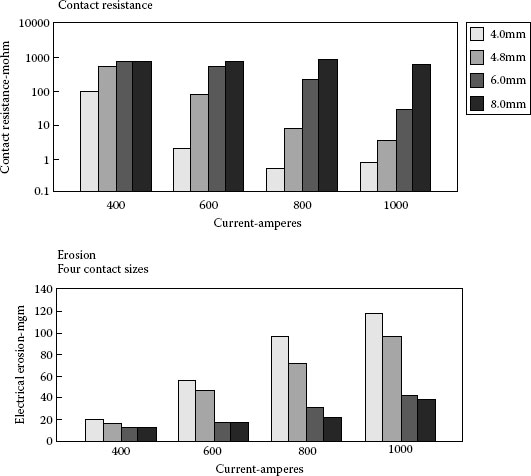
FIGURE 16.23
Contact resistance and electrical erosion versus switching current level for four different contact sizes at each current level [93].
The data in Figure 16.23 also shows that the erosion rate increases as the contact area decreases for a fixed current, hence as would be expected, an inverse relationship exists between erosion rate and contact resistance. The erosion rate for the two smaller contacts increases significantly at about the current range where the contact resistance drops off. For lower switching currents, under 100 A, such as the rated currents used by devices such as molded case circuit-breakers, the arc energy is not high enough to erode away the oxides that are building on the contacts with switching duty. For this reason much of the research has concentrated on studying resistance changes for lower current loads.
Since tungsten–silver and tungsten–carbide–silver are the most popular materials for these devices most of the work has focused on these systems. In order to better discuss results Table 16.5 is included to show some properties of the oxides of tungsten. Tungsten forms many oxide compounds with three of the most common shown in Table 16.5.
TABLE 16.5
Properties of Tungsten Compounds
Compound |
Color |
Density (g cm−3) |
Melting Point (K) |
Comments |
W |
Metallic |
19.3 |
3683 |
Oxidation begins at 673 K |
WO2 |
Brown |
11.4 |
1543 |
Heating in air converts to WO3 |
WO2.95 |
Blue |
Heating converts to WO3 |
||
WO3 |
Yellow |
6.47 |
1743 |
Vaporizes 1273 K, decomposes 1573 K |
Ag2WO4 |
Yellow |
823 forms |
Silver tungstate, unstable 973 K |
Source: Data from P Slade, IEEE Trans. Components Packaging and Manuf Technol—Part A 17 (1): 96–106, 1994; J Kaminski, Proc. 9th Int'l Conference on Electrical Contacts, p. 25, 1978; K Schroder. Thesis TU Braunschweig, 1967.
Between brown and yellow oxides, tungsten has several intermediate oxides and the colors go from brown to reddish blue to blue and finally yellow as the tungsten gains in oxygen content [112]. The conversion of tungsten to yellow oxide involves a large drop in density, and about a three to one increase in volume. Since resistance is a function of the volume fraction of conductors in a solid, it can be seen that this change in density will dilute the concentration of the conductors; thus, when a portion of the metallic tungsten phase converts to an oxide the volume fraction of metallic tungsten left for conduction decreases not only by the amount of tungsten fraction converted but also by an additional amount related to the additional space occupied by the tungsten oxide compared to the original metallic phase. This is much different than the mechanisms for increased resistance in silver metal oxides, since in those cases the oxides already exist and resistance increases through dilution of the conductive phase, silver. The WO3 oxide is stable in air to 1,000°C where vaporization begins and decomposes at 1,300°C [112]. The oxidation of tungsten–silver is further complicated and the resistance problem is also further aggravated in that silver, which is normally free from oxides at elevated temperatures, in the presence of tungsten can combine with tungsten and form oxide compounds. This has been known for a long time and several researchers have identified and reported finding the compound silver tungstate, Ag2WO4, on arced tungsten–silver contacts [108,113,114]. Slade has shown the presence of crystals, cubic or orthorhombic in appearance, having compositions close to silver–tungsten on arced tungsten–silver, see Figure 16.24 [115]. Other researchers have reported the silver tungstate to have an appearance of a glass [116,117]. Silver also combines with tungsten to form amorphous silver tungstate, which may explain the difference in appearance and also the reason why some researchers using x-ray diffraction analysis on arced tungsten–silver contacts find only small amounts of silver tungstate, or none. Leung et al. have performed experiments on the oxidation of tungsten-silver materials and have found at 600°C a 30 μm layer of oxides formed which contained small isolated silver islands, WO3, Ag2WO4, and a small amount of NiWO4 [116]. Oxidation done at 700°C produced a much thicker oxide layer, 60–400 μm, and similar compounds except no Ag2WO4 is present. The layer is composed mainly of WO3 and a large amount of segregated silver. The presence of this much silver compared to the silver in the oxide layer that formed at 600°C supports the non-existence of Ag2WO4 even in an amorphous state. It can be concluded from this that Ag2WO4 is not stable at 700°C. Silver also combines with molybdenum to form Ag2MoO4 but this compound has not been reported by researchers on arced molybdenum-silver, possibly since it can also exist as an amorphous compound [117]. Thus, it can be seen that, since silver also can be consumed as an oxide in the presence of tungsten, heating the tungsten–silver in air can theoretically convert the surface from a metallic to almost total oxide state. From the previous chapters it was explained that the temperature of the arc is very high and above temperatures where these oxides are stable. Therefore, the oxide layers form on the surface of the contacts just outside the arc roots during arcing and on the arc reacted surfaces after the arc is extinguished.
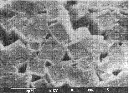
FIGURE 16.24
Silver tungstate crystals found on arced tungsten–silver [115].
Leung and Kim have performed switching studies at 30 A for three refractory metal systems, tungsten–silver, molybdenum–silver, and tungsten carbide–silver all at 50% by volume silver [92]. The contact resistance measurements have been made at the same current as switching duty, 30 A and results are reported as voltage drop in millivolts (see Figure 16.25). Here, as a result of the lower switching current, the percentage of contact surface area melted by each arcing operation is much smaller than the 50% area cited by Lindmayer and Roth for maintaining low contact resistance, as discussed above. The voltage drop is seen to increase quickly for the first few hundred operations for tungsten–silver and at a slightly lower rate with molybdenum–silver and significantly slower with tungsten carbide–silver. At a switching life of 2000 operations the tungsten–silver is significantly higher in resistance than the tungsten carbide–silver but after 6000 operations all three materials are much closer although the tungsten–silver is still the highest in resistance. The erosion in this case did not follow an inverse relationship to the resistance, since they reported that the tungsten–silver contacts also had the highest erosion rate. In analysis of cross sections of the surface layer after testing, Leung and Kim found the tungsten carbide–silver material to have a layer with much more free silver, mainly segregated below the rest of the arc product layer, than was found for the layer of arc product on tungsten–silver. They also found a small amount of silver tungstate in the tungsten–silver layer and none for the tungsten carbide–silver material. These findings indicate that tungsten carbide being present versus just tungsten, may retard the oxidation of tungsten and formation of silver tungstate.
Witter and Abele have investigated the effect of composition, percent refractory metal, and also the size distribution of the microstructure on the contact resistance of tungsten–silver after switching [110]. This work was done at 20 amperes current for both switching and measurement on 4.8 mm contacts. Figure 16.26 shows the results for 4000 operations and it can be seen that as the volume percentage of tungsten increases in the tungsten–silver material the resistance increases. The fineness of the microstructure had a small influence with the coarser materials having slightly lower resistance. Cross sections made of all of the materials showed little difference among the materials for the oxide layers thickness. The oxide layers contained three types of inclusions, melted silver particles, and small chunks of tungsten–silver and melted tungsten particles. The amount and type of inclusions varied with composition and also fineness of structure. The high-silver compositions and the coarse materials had more and larger silver inclusions. The high-tungsten compositions had very few silver inclusions and many melted tungsten particles and cones. It also was reported that the voltage drop decreased significantly over the first few minutes of measurement. This was thought to be the result of softening and melting of the surface layer in the areas of constriction. The final resistance seemed to correlate with the amount of silver inclusions in the oxide layer which in turn was related to the amount of silver in the bulk material.
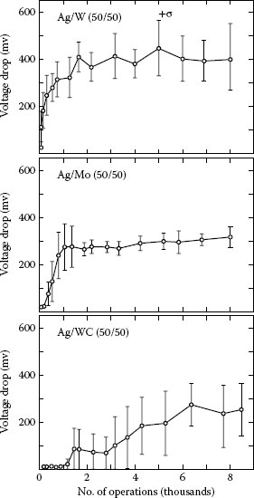
FIGURE 16.25
Average millivolt drop versus operating life for 50% by volume W/Ag, Mo/Ag, and WC/Ag switching 30 A at 100 V ac with a 4.7 mm diameter contact [92].
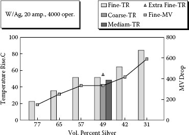
FIGURE 16.26
Temperature rise and resistance in terms of millivolt drop versus silver composition and microstructure for W/Ag after switching 4.76 mm diameter contacts [110].
Slade did extensive studies of the voltage-drop characteristics for tungsten–silver 50 volume percent silver [115]. The work was done at 20 A on 4 mm diameter contacts and the voltage drop was continuously measured. The contacts were switched for 3000 operations and the contact resistance increased with contact switching life. Slade noted that the voltage trace varied considerably with the condition of the contact and described four typical types of voltage stability as follows (see Chapter 10, Figure 10.58):
• Type 1: A steady millivolt drop of less than 100 mV with no excursions. Typical for new and low switching life.
• Type 2: A plateau voltage from 200 to 600 mV with rapid excursions to lower voltages, indicating a semi-stable high-resistance contact surface.
• Type 3: Semi-stable mean voltage in the 400 mV range with continuous rapid oscillations of up to ±100 mV, indicating an unstable surface structure superimposed on a more stable high-resistance surface.
• Type 4: More violent type 3 oscillations with peaks as high as 1.3 mV leading to periods of lower stable voltages (200–300 mV), indicating an unstable high-resistance surface with periods of lower resistance.
Slade also developed Table 16.6 which uses the Kohlrausch voltage drop to temperature relationship to indicate possible reactions taking place at different millivolt readings. The voltage instabilities noted for tungsten–silver are in the range for the decomposition of silver tungstate (<300 mV) and tungsten oxides (390–490 mV). A significant conclusion from this work is that tungsten–silver contacts are self-limiting for contact resistance as a result of the oxide decomposition mechanisms. Thus, since all of the oxides possible on the surface of tungsten–silver decompose at or below 1300°C and tungsten melts at about 3400°C the time for millivolt drop excursions above the decomposition or melting temperature of tungsten oxides should be short and the upper limit for the excursions should be in the range of 1100 mV. Therefore, no thermal runaway conditions are expected for tungsten–silver contacts, although they may have high surface resistance and a resulting high temperature rise.
TABLE 16.6
The Vc Value for Temperatures at Which Physical and Chemical Effects Occur for the Ag, W, O2, and C System
MV |
Temperature (°C) |
Oxidation, Softening, Melting Effects on Ag and W Contact Materials |
110 |
180 |
Softening temperature of Ag, AgO2 begins to decompose [114] |
155 |
310 |
Ag2O decomposes [114] |
225 |
500 |
Initial oxidation of W begins as a compact protective film but as it becomes porous, the oxide film grows by oxygen diffusion [121] |
235 |
550 |
|
255 |
580 |
|
260 |
600 |
Formation of Ag2WO4 on heated Ag-W contacts [107], Ag2WO4 melts [102] |
295 |
700 |
Oxidation rate of heated Ag-W contact is twice that at 600°C with the formation of WO3 and perhaps WO2 but no Ag2WO4 [107] |
330 |
800 |
|
380 |
960 |
Melting temperature of Ag [114] |
390 |
1000 |
Softening temperature of W [114]. Above this temperature evaporation of W oxides increases, with the extent of evaporation being affected by the partial pressure of oxygen [121]. Conducting W3O8 can form with the reaction of W and WO3 [102] |
490 |
1300 |
W oxides evaporate as soon as they form. At high pressure a boundary layer of evaporated oxide limits the access of oxygen to the surface [121] |
545 |
1470 |
WO3 melts but can sublime at a lower temperature [121] |
780 |
2210 |
Boiling temperature of Ag [114] |
1140 |
3410 |
Melting temperature of W [101] |
There also has been work done on other silver refractory systems and minor additives to the tungsten–silver and tungsten carbide–silver systems in search for materials with lower and more stable contact resistance on switching low-current loads. The system silver–titanium carbide and silver–tungsten carbide–titanium carbide were investigated and found to have improved contact resistance compared to tungsten–silver at low currents [111,118,119]. These materials never developed for several reasons: the difficulty for manufacturing, low silver content retained after higher-currency switching, and the formation of a slag on the contact surface from low-density TiO2 which gave rise to high Rc [119]. The additions of nickel up to a few per cent by weight was investigated by Witter and found to lower the resistance of tungsten–silver materials after switching [95]. It was also found that the addition of nickel increased the erosion rate and lowered the dynamic welding resistance of the material. A similar effect was found by Kabayama for cobalt additions to tungsten–silver [96].
Slade et al. investigated the effect of additions of graphite, 0.5 to 1, to tungsten carbide–silver with high volume percentages of silver [120]. These materials exhibit considerable improvement for resistance performance as a result of the high silver content and graphite reducing the oxidation of the tungsten, but it must be kept in mind that the erosion and anti-welding must probably have also been compromised.
From the above, it can be seen that the resistance of silver refractory metal systems is a complex subject that does not have easy solutions. The surface of the materials changes after arcing and forms a surface that is a product of both the load it is switching and its own bulk properties. The characteristics of this layer will influence the performance of the material with respect to erosion, anti-welding and resistance. As seen above, adjustments in the material for improving resistance results in also changing the other properties. With regard to contact resistance, one point of distinction between silver refractory metals and silver metal oxides, which is important to understand, is that for silver metal oxides the change in contact resistance on switching is in general smaller than that seen for silver refractory metals. The reason for this is that for silver refractory metals the silver content is diluted beyond just the evaporation of silver from the surface, but by the growth of the refractory oxides and also consumption of silver in forming silver metal oxide compounds. For this reason, the use of these materials is usually in devices that employ high contact forces and wiping motion of the contacts on closing to mechanically disrupt surface oxides that have formed and create a low Rc region.
16.4 Vacuum Interrupter Materials
This is a very specialized area of contact materials. The subject of vacuum interrupters was introduced in Chapters 9, 14, and 15, and they also contain information on the contact materials that are used in them. A good reference on this subject is a review written in 1992 by Slade of the advances in materials for high-power vacuum interrupters which explains the unique material requirements for these materials, compares the different types of materials in use, and lists 68 references on this subject [121]. He updated this paper in the book published in 2008 [122]. Three main types of materials have dominated this market, copper-bismuth alloys, tungsten–copper type composite refractory materials, and chromium-copper contacts. At this point in time most of the copper bismuth materials have been replaced by chromium copper which is by far the dominant material for vacuum interrupters. The commercial type materials that are made and used for vacuum interrupters can be divided two groups today:
1. Tungsten–copper or tungsten carbide–silver
This type of material is similar to these materials discussed earlier in this chapter, except that these materials have special processing to be suitable for vacuum application. As a result of interruption limitations these materials are usually limited to lower-current vacuum interrupter designs applied to load switches with currents less than about 2000 A [121]. Some work has been investigating problems with tungsten copper materials with high tungsten content, 90/10 W/Cu, Li el al. [123]. It was found that this material had cathodic type pip and crater erosion that left a pip on the anode and a crater on the cathode. The investigation showed that tungsten copper with a higher copper level, 30%, had smooth erosion compared to the 90/10 material. The cause of this problem was thought to be from that for the high tungsten material, the cathode spots (see Section 9.6) were slow to move from its bridge initiation area too long. Follow up work was done by Taylor [124] who made measurements with a high speed video camera. He found that there was about a 4 msec delay in the initial transition mode on contact opening that resulted in a high current density near the original bridge column. Some measurements he made on chrome coppers showed that the arc expansion during transition mode was 3.7 times faster than for tungsten copper. He also agreed that the erosion pattern for tungsten copper 70/30 was much improved over 90/10 W/Cu for providing a more even erosion and less with pip and crater formation. It should be also recalled from a previous section of this chapter that a higher erosion rate can also have an effect on reducing the probability of pip and crater erosion.
2. Chrome–copper
Chrome–copper is just as complicated as composite refractory metal contacts and maybe more. There are several different processes used for making this material which results in not only different properties but different metallographic structures. Hauner et al. [125] and Slade [122] provide some detail descriptions of the various processes and some general properties. A popular process is the press, sinter, repress, and annealing process. The sintering is done in the solid state and normally there is some level of porosity even after repressing and annealing. The microstructure is quite coarse compared to tungsten refractory metals. This is probably the most economical of the three main processes used.The infiltration process involves pressing a chrome or chrome rich skeleton, sintering it, and infiltrating the skeleton with copper. Since the infiltration is done at a high temperature above the copper melting point the bonding of the chrome and copper is very good. The chrome coarse similar to the press, sinter repress process. The process produces bars that are over 99% dense. After bars are formed with this material they can be cold extruded into smaller and longer bars. This results in an anisotropic structure with elongated chrome particles parallel to the rod. Melting and very fast freezing is the third process for making chrome copper. Induction melting of a chromium copper power mixture or arc melting chromium copper rods in an argon atmosphere is the first stage. The molten mixture is then very rapidly cooled in a water cooled crucible. This results in a copper matrix with very fine chromium inclusions. Large ingots can be produced that can be cold extruded into smaller and longer rods. The material is 100% dense and the structure is finer grained than the other two processes. Typical compositions for chrome copper are in the range of 25–50% chromium. In looking at the sophistication of the processes, it is believed that consistency of processing is very important. They are not generic and although two companies may use similar processes the material may be quite different. For any material that is evaluated it is important to record as much information as possible about the chemistry, microstructure and physical properties. In the literature there are some comments that infiltration process experiences less cracking on arcing than the press, sinter and repress materials. There is no experimental data to back those claims and it would be interesting to see some data on toughness measurements.
Tungsten as a result of its high melting and boiling points, highest of all the metals, and high electrical conductivity has been used for many years as a contact for special applications (see Chapter 24, Table 24.1). It is mainly used in applications which require high-frequency switching like automotive ignition systems and horn contacts. Tungsten contacts form oxide layers not considered protective on air exposure that reach about 50 Å at room temperature. By use of high contact force to break through most of the oxide layers, electron tunneling through the remaining layers of oxide can maintain reasonable conduction with tungsten contacts [126]. Forces of 5 N or more are common for devices using tungsten contacts. During arcing, as seen in the last section on composite materials, tungsten will be oxidized under the heat of the arc. Tungsten has many oxide compounds that are progressively oxidized to WO3 and then sublimed. Recalling from Table 16.6, all tungsten oxides evaporate as soon as they are formed at or above 1300°C. Typical erosion of pure tungsten contacts shows WO3 around the arc spot and a coating of thin sub-oxides in the center of the arc spots. Tungsten contacts were very popular for high-frequency switching operations, hundreds of operations per second, since it has low electrical erosion, but are not good for applications where contact force is not high, hundreds of grams, and the contacts must carry high currents for long periods in the closed position. High heating in the current constriction area can lead to oxide build-up and without mechanical wiping movement of the contacts high resistance can result with device overheating and or device failure [127]. This, of course, will depend on the current level and device contact forces. The usage of tungsten contacts began decreasing in the 1970s and 1980s as a result of replacement of electromechanical devices in which they were used, like automotive ignition systems, by solid-state devices.
Table 24.2 in Chapter 24 lists some of the common silver and silver copper alloys. Since these materials are made by melting and casting these alloys are much more consistent from supplier to supplier and batch to batch. For that reason there is no need to discuss variations as a result of processing. Fine silver and these alloys are some of the first contacts that were used yet very little is found in the contact literature discussing research or comparing electrical switching properties of these materials. The purity of these alloys can vary but is normally based on 99.95 wt.% silver as the alloying ingredient.
Fine silver has the highest conductivity of all metals and as a result is useful in low-current applications, where resistance is critical owing to the low contact force. The oxides of silver are not stable at elevated temperatures and decompose at 200°C, and it is relatively stable to oxidation at room temperature except in the presence of pollution such as ozone [126]. The problem with silver with regards to corrosion is with the formation of sulfides and chlorides. This is discussed in detail in Chapter 2 and therefore will not be discussed here. For normal arcing applications the contact force, contact wiping, and circuit voltage and current are above values where corrosion of silver is a concern. Of the non-noble silver alloys, not containing noble metals such as palladium, fine silver offers the lowest resistance choice since Ag2S forming on this alloy is soft and low in mechanical strength [128]. There is little data comparing electrical erosion characteristics of fine silver to other materials. For make bounce erosion, it is listed as having high erosion compared to silver–nickel and the silver metal oxides [67]. For break arcs some comparisons are published for long arcs where fine silver is shown to be very anodic and to yield lower erosion than palladium alloys [129]. Generally, fine silver is limited to low-current applications. Some contact brochures suggest 1 A as an upper limit and others 10–20 A. The current is only one factor for consideration of a contact and other factors like load type are also important. Fine silver is a common contact for small snap-action thermostats which switch low currents and resistive loads.
16.6.2 Hard Silver and Silver–Copper Alloys
This term is used with silver alloys which have a small amount of nickel and or copper to increase the hardness. Again little research data is published on these materials. Nickel in small amounts increases the hardness of the silver without having much effect on the conductivity. Silver–nickel will be discussed in the next section as a separate category of contact material. Copper additions to silver as seen in Table 24.2 in Chapter 24 lower the melting point and decrease the electrical conductivity of silver–copper alloys. Silver and copper form eutectic type alloys with a eutectic melting point of 779°C [79]. Contact brochures indicated less electrical erosion wear of silver–copper alloys than fine silver but more erosion wear than silver–nickel. It is also indicated that dc transfer is less for alloys with 10% or more copper. Leung and Lee found that a silver copper 2 wt.% alloy performed well for automotive resistive and inductive loads in keeping low contact resistance, but that it welded and had high transfer for lamp loads compared to silver–tin oxide [58,59]. Under high make currents typical of lamp loads coupled with contact bounce, silver–copper alloys tend to erode at a very high rate compared to silver metal oxide contacts. Figure 16.27 compares erosion of silver–copper 2 wt.% to a silver–tin oxide 11% alloy for erosion under long bounce (>2 ms), with 100 A inrush current at 12 V dc as the copper content of silver copper alloys increases, the resistance of the material to corrosion decreases. For this reason, silver–copper alloys are normally limited to less than 30% copper. Silver copper alloys, similar to fine silver, are recommended for lower-current applications, with contact companies generally setting limits under 20 A.
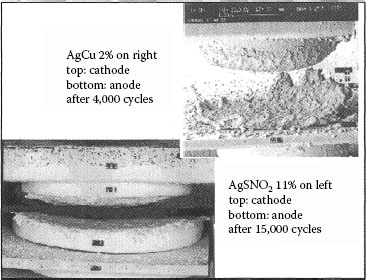
FIGURE 16.27
A comparison of silver–copper 2% alloy and silver–tin oxide 11% alloy after switching a 100 A inrush lamp load [12].
16.7 Silver–Nickel Contact Materials
A very popular type of contact material used worldwide, and especially in Europe, consists of silver–nickel contacts (see Chapter 24, Table 24.3). These are powder metallurgical contact materials since silver and nickel have virtually no mutual solubility. This makes them somewhat analogous to tungsten–silver except the nickel is used in much lower percentages similar in volume percentage to the oxide level in silver metal oxides. The sintering is done in the solid state and the process options for making these materials are similar to those used for powder metallurgical silver metal oxides. The conductivity varies with the volume percentage of silver since there is no decrease in the silver conductivity from alloying. Like powder metallurgical silver metal oxides silver–nickel contacts can be made by pressing, sintering, and coining individual parts or by wrought powder methods involving sintering a billet followed by extrusion or alternative forming methods. The wrought method produces fully dense materials, free of porosity. The particle size distribution of silver–nickel contacts can be varied greatly by the powder metallurgical processes used for making the powders and blending the powders. The nickel particle shape can also be varied for these materials by variances in starting powder combined with different wire and strip forming techniques.
A study of the particle size and shape effect on electrical erosion was done by Behrens et al. [130]. They tested materials which varied in particle size from submicron to over 100 μm). They also had materials which had nickel fibers perpendicular to the contact face and parallel to the face. The tests were conducted for break only at 115 A and 220 V ac AC-4 testing. The results showed no correlation for erosion with particle size. The orientation also only made a difference for the initial part of the testing until an equilibrium layer of silver nickel melt material had been established on the contact face. They concluded that silver–nickel is a unique material since it establishes a nickel particle distribution on the surface as a result of nickel melting and dissolving in the silver to a small extent during arcing and then re-precipitating on the surface. Therefore, regardless of the starting microstructure the surface melt layer microstructure is similar for a given arcing condition. It must be kept in mind that this study was limited to break erosion only and since the make erosion process is different these conclusions cannot be extrapolated to make and break results.
Balme et al. compared three silver nickel materials and both fine silver and silver metal oxide materials [131]. The testing was done in an automotive relay with relatively high contact force, 2 N, for lamp loads with over 100 A inrush current on closing. The results were reported in terms of contact resistance after endurance welding, and sticking that occurred during testing. For welding resistance all three silver nickel grades, 10–40% nickel, showed make welding resistance slightly better than fine silver but significantly inferior to the silver metal oxide grades. With regard to contact resistance, the 90/10 Ag/Ni material was just a little higher than fine silver but the 30% and 40% nickel grades were significantly higher and similar to the silver metal oxide materials. Leung and Lee tested silver–nickel in automotive relays and compared a 90/10 material to silver–tin oxide and silver–copper contacts. They found that the silver–nickel was intermediate for contact resistance with silver–copper and silver–tin oxide, but showed a higher amount of material transfer than either of the other two materials [58]. One of the reasons silver–nickel is very popular is that it can be directly welded onto copper substrates from wire. This lowers the contact assembly costs. This same advantage for fabrication is a disadvantage for limiting applications where the high currents cause contact welding in a device. Depending on the device and type of load silver–nickel materials work best in devices not exceeding currents of 50–100 A.
16.8 Silver Alloys and Noble Metals
16.8.1 Palladium and Silver–Palladium Alloys
The most common alloys of this category are silver–palladium alloys and palladium (see Chapter 24, Tables 24.2 and 24.7). These alloys have been used for many years in mainly telecommunication switching applications which require low electrical noise, therefore more stability in contact resistance. These alloys containing noble metals are generally more chemically stable and resistant to corrosion than non-noble silver alloys and silver metal oxide contact materials. The corrosion properties of the noble metal alloys are discussed in Chapters 3 and 8 and therefore will not be covered here. The telecommunication circuits that used relays with these materials operated at low currents near or below the minimum arcing current, so that normally the electrical erosion properties of these materials was not as important in these applications as the stability of these materials from forming resistive films. Arcing did frequently occur in these applications as a result of organic vapor contamination resulting in contact activation. Contact activation can lower the minimum current required for an arc to occur, activation is discussed in Chapters 10 and 19. These materials were thus used as arcing contacts but were mainly developed for low current or dry circuit switching use. After 1980 the switching function for these signal type circuits was largely converted from electromechanical relays to solid-state devices. Since noble metals are 10–100 times more expensive than common silver alloys, the use of these metals is limited to applications where there is an absolute need for their properties. These types of alloys are still used in some signal type circuits, but also in some higher current applications where corrosion resistance is important.
The silver–palladium alloys and palladium differ from silver alloys and metal oxides as a contact material in more ways than just being more chemically stable. The higher palladium-containing silver–palladium alloys are shown by Sawa et al. [132], to be more stable to changes in contact resistance as a result of electrical arcing than fine silver. They studied changes in contact resistance after 20,000 switching operations at 1.2 A for both make and break at 24 V dc. The largest difference was for break arcs several milliseconds in duration; palladium increased only 20% in contact resistance compared to a 60% increase for silver contacts. For protection against corrosion and oxidation for palladium silver alloys in many applications a thin gold overlay is put over the palladium silver alloy. Tamai [133] investigated the use of dopants in the palladium silver alloy to give it more resistance to oxidation on exposure to high temperatures. He found that the additions of 1% or less of magnesium to the alloy improved the alloys ability to retain a low contact resistance after being exposed to high temperatures. A thin diffused silver layer formed on the surface with the addition of magnesium. The mechanism is not clear for the formation of this layer but it resulted in less oxidation on the surface. It should be kept in mind that the gold will still be better for corrosion protection for non-arcing applications but if arcing is present the gold will be burned off.
With regard to electrical erosion, interruption studies done in the range of 5 A at 20–48 V dc show the erosion rate for pure palladium to be much higher than for fine silver [134,135]. Chen and Sawa compared the electrical erosion of silver contacts, palladium contacts and combination pairs of silver contacts mated with palladium contacts [134]. This study was done using an inductive load which produced relatively long arcs, 1–4 ms at 20 V dc. Comparisons were made in terms of anode and cathode losses or gains and net losses for both the anode and cathode combinations. At low currents of 1 A or less, the differences among the materials were small. A comparison of the erosion at 4 A is shown in Figure 16.28 from data taken from work by Chen and Sawa [134]. This figure serves well to illustrate the differences in interruption erosion between palladium and silver. As a result of the long arc both the Ag–Ag and Pd–Pd contact pairs exhibit similar cathodic erosion. The net erosion, sum of cathode loss plus anode gain, is quite different, with silver showing very little loss compared to palladium. This difference is the result of a higher percentage of the material eroded from the cathode transferring to the anode for silver as compared to the percentage of eroded material transferring to the anode for palladium. The reason for this difference is not explained but some possible factors causing this will be discussed. From the data it can be seen that the gap at which the gaseous phase began for silver was shorter than where the gaseous phase began for palladium. A shorter gap should provide a higher ratio of material transfer versus eroded material being lost. The oxides of palladium are stable at higher temperatures than the oxides of silver. PdO forms on heating above 700°C and begins to decompose at 870°C. Some metastable oxides also form between 900°C and 1300°C [136]. The sticking coefficient for deposits of palladium on the anode may be affected by this. Figure 16.28 also shows some interesting results for the erosion of contact pairs containing both silver and palladium contacts. Those pairs that have the palladium contact as a cathode and a silver contact as an anode show erosion results similar to palladium pairs. The pairs that have silver as a cathode and palladium as an anode have results similar to silver pairs. Since the erosion is mainly cathodic, transfer from cathode to anode, for these long arcs the cathode material controls the erosion process. For example, for the silver cathode and palladium anode pair, the transfer of the silver from the cathode material onto the anode soon results in two contacts with silver surfaces.
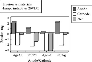
FIGURE 16.28
A comparison of electrical erosion for silver and palladium contacts after 60,000 operations.
Sone et al. show the erosion characteristics as a function of composition for a full range of silver and palladium alloys (see Figure 16.29 [135]). It can be seen that the erosion generally becomes more cathodic as the palladium content of the silver–palladium alloy increases. A large change in the erosion rate between pure silver and silver–palladium 10% is not explained. Silver and palladium form a solid solution alloy with complete solubility [79]. This results in a very sharp drop in conductivity as palladium is added to silver; see Figure 16.30. Possibly this might be a factor for influencing this type of shift in erosion. In comparing the results for pure silver and pure palladium in Figure 16.29 to Figure 16.28, it must be noted that the results in Figure 16.25 are expressed in erosion per number of switching cycles and Figure 16.29 is expressed in terms of erosion per arc second duration. For the switching represented by Figure 16.29, resistive load, the arc duration for the palladium contacts is reported as much shorter, a quarter to a tenth of the arc duration for the silver contacts. Taking this into account the results are comparable.
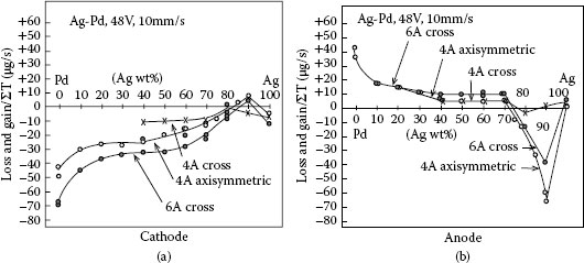
FIGURE 16.29
Electrical erosion of silver palladium alloys as a function of composition for interruption testing at 48 V dc resistive load, with a slow opening speed of 10 mm s−1, for cross bar and cylindrical contacts, and erosion expressed as μg per second of arc duration [120].
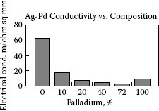
FIGURE 16.30
The electrical conductivity of silver palladium as as function of composition.
For erosion characteristics for contact make and shorter duration break arcs little published data was found. Palladium contacts are used in some automotive applications for special relays which are used to control lamps as hazard flashers. This relatively expensive material, as compared to silver-based contacts, is used since it erodes slowly in these applications and offers long switching life. This is mainly owing to the shorter arc duration found for switching resistive loads with palladium versus silver-based contacts as shown for palladium ruthenium contacts versus silver tin oxide contacts in Figure 16.31 [137]. From the above it can be seen that palladium alloys offer only lower resistance as an advantage for interrupting circuits which produce long arcs. For make and break dc applications such as automotive circuits, as a result of the good interruption properties of palladium these alloys offer longer switching duty life.
Another metal from this group that is occasionally used as an arcing contact is platinum. It is similar to palladium in electrical conductivity but has a higher melting point, 1773°C. Platinum also has a very high density, 21.45 g cm−3, which, coupled with its very high price per ounce, make it a very expensive material to use as a contact. As an arcing contact material little has been published about platinum. Platinum can form some oxides but these oxides are only stable in a narrow temperature range, 900–1200°C [79,126]. Thus, oxidation is not a problem for using platinum as an arcing contact. Platinum has been used, but to a much lesser extent, in applications similar to where tungsten contacts are used such as distributor contacts. In these applications the contacts are subjected to millions of rapid and repetitive switching operations and a low duty cycle for carrying current. The platinum offers good erosion resistance plus more stable contact resistance than tungsten. In the 1980s solid-state devices, to a large extent, have replaced electromechanical distributors. This has cut down further the use of platinum as an arcing contact.
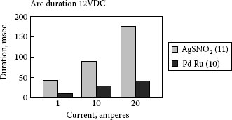
FIGURE 16.31
A comparison of arc duration in μs for clean AgSnO2 89/11 and Pd/Ru 90/10 contacts interrupting resistive loads with an opening velocity of 1.5 m s at 12 V dc.
16.9 Silver–Graphite Contact Materials
Silver-graphite is a popular brush material (see Chapter 24, Tables 24.3 and 24.12) as a result of its anti-welding and electrical resistance properties (see Chapter 20, Chapter 21 and Chapter 22). In this section, the discussion is limited to these materials used for arcing contact applications. For these applications the composition range of 2–5% graphite by weight, 9–20% by volume, is the most popular. Since graphite is very low in density compared to silver the volume percentage range compared to the weight percentage range is quite different. Silver–graphite is a composite material like previously discussed silver metal oxides. It is also manufactured by powder metallurgical methods since silver and graphite do not form any alloys. It is manufactured by a variety of powder metallurgical methods, including pressing, sintering, and extrusion of ingots to form wrought silver–graphite strip and wire and also the conventional press, sinter, and repress method. One of the differences in processing of silver–graphite from silver metal oxides is that it must be sintered in a protective atmosphere to prevent oxidation of the graphite.
Both the particle size and shape of the graphite phase can vary to a large extent for these materials [138,139]. The particle size can vary from submicron sizes to over 100 μm and the shape of the particles can be flakes, fibers, or spherical. Silver–graphite materials are noted for good anti-dynamic welding properties and stable and low-contact resistance [67,138,140]. The disadvantages of these materials are high electrical erosion rates and poor arc mobility (see Section 14.1.3 and Figure 14.32). Wingert et al. investigated the effect of particle size on the electrical erosion, dynamic welding resistance, and contact resistance of Ag/C, 95/5 wt.% materials [138]. They made materials with both 4 μm and 20 μm graphite and found that using the coarser graphite, the materials form very large silver mounds on the surface compared to the finer grade of silver–graphite. The results show that the coarser materials have poorer anti-welding resistance than the finer grades. The electrical erosion rate is higher for the finer particle materials. As the graphite particles become smaller the silver to silver grain boundary bounding is lowered, less contiguity of silver grains. This weakening of the contact structure by the decrease in silver to silver bounding results in higher erosion rates.
In devices such as current-limiting circuit-breakers, the silver–graphite contacts are frequently used as one contact component in unsymmetrical contact pairs. Turner and Turner investigated the use of silver–graphite contacts paired with fine silver contacts in railroad switches [141]. They found that there was a polarity effect with regard to the electrical erosion. This work was done at 250 V dc at 50 A for make arcs formed by opening and re-closing after 4 ms of arc time. In this study the silver–graphite showed lower erosion when used as the cathode than when it was used as an anode. The contact resistance was also lower when the fine silver was the anode and the silver–graphite was the cathode.
Lindmayer and Schroder found different results in studying unsymmetrical silver–graphite contacts paired with both copper and tungsten–silver contacts [140]. Their erosion test was done in a test fixture for interrupting a 220 V half-cycle current from 350 to 1000 A. Their tests show that the erosion resistance of silver–graphite paired with either material was much better when the silver–graphite was used as the anode than when it was used as a cathode. This is explained from erosion results of symmetrical pairs of silver–graphite under similar conditions. For symmetrical pairs of silver–graphite contacts erosion over an entire current range of 350–1000 A shows the erosion to be primarily cathodic with the ratio of the total erosion contributed by the anode ranging from nothing to a maximum of 20%. The difference in this work from that done by the Turners is that the Turners’ work used shorter arcs with contact make which would tend to be more anodic in terms of erosion than tests done for only interruption. Lindmayer and Schroder also investigated dynamic welding resistance of the unsymmetrical contact pairs [140]. They conducted these tests in a fixture which created a contact bounce of about 3–4 ms. They show the weld strength to be lower when the silver–graphite was the cathode rather than the anode for both mating with tungsten–silver and copper. The difference between the two unsymmetrical pairs owing to polarity were much smaller and insignificant compared to the differences of these pairs to the much higher welding strengths generated by copper or tungsten–silver symmetrical pairs.
For contact resistance, tests were conducted in conjunction with the interruption cycling tests. They found that the resistance was also significantly affected by the polarity. If the silver–graphite was the cathode the resistance was less than 0.1 mΩ for both mating tungsten–silver and copper. For opposite polarity the resistance was much higher and in some cases over 100 mΩ. An explanation of this is that for the polarity of silver–graphite as the cathode the erosion rate was very high and resulted in a reducing atmosphere of C and CO which reduced the metal oxides and the contact electrodes. For the opposite polarity, recalling from above, the erosion rate of the silver–graphite anode was very low and, therefore, did not generate as much of a reducing atmosphere.
This work also shows that the poor arc mobility of silver–graphite can be improved on by using unsymmetrical contacts with the silver–graphite as the anode. With this configuration the arc mobility is shown to be intermediate between the mating cathode material and silver–graphite.
Vinaricky and Behrens [142] did a very thorough study of silver graphite that covered the questions of the importance of graphite particle orientation and also studied the erosion characteristics under different gasses and electrical loads. The question on the importance of fiber orientation, parallel or perpendicular to the contact surface, was that the processes were different for making the two different orientations. The extrusion process for making the perpendicular products produced fully dense material and the rolling process for parallel fibers had some porosity. This investigation the made samples of both materials using extruded silver graphite and machining it in different directions to get parallel and perpendicular samples. The other part of the study involved testing the materials in air, nitrogen, oxygen, and argon using the long arc. For this material the testing for long and short arcs is quite different as shown above from other research. First, for the short arc, the perpendicular fibers had lower erosion but this changed for the long arc where it didn’t seem to matter. Many of the applications are for long not short arcs. The other big finding was that under argon the erosion was almost nothing compared to the rest of the gasses. The results for air, oxygen, and nitrogen were very similar. The conclusions were that even under nitrogen there are chemical reactions taking place during arcing that increase the erosion rate for silver graphite. This is an interesting finding showing chemical reactions during arcing are responsible for the high erosion of silver graphite. This is also an interesting finding especially for devices that have a protective atmosphere.
Arcing contact applications cover a very wide range of applications in terms of current levels being switched, types of electrical loads, voltages, ac versus dc ambient conditions, and mechanical opening and closing forces and velocities. Table 16.7 shows some of the common types of arcing contact applications matched with typical materials used at different current levels for those applications. As a result of the many differences in devices and electrical loads, certainly many other combinations of contacts versus applications exist. In this chapter it has been stressed that for composite materials like silver metal oxides and silver refractory metal materials that generic classification by chemistry is inadequate for comparing and allowing substitution of materials for specific applications. The chapter discussed how variations in processing and or small amounts of additive could significantly change performance results of materials. For the purposes of the table above the material designations are meant to be very general or generic, thus AgSnO2, is meant for example to represent all types of silver tin oxide, AgSnO2, AgSnO2 + Bi, AgSnO2IN2O3, etc. Thus, this table gives you a general idea of where different materials are applied, but the chapter shows that a much more detailed understanding of the materials being evaluated is required in making decisions on arcing contacts.
TABLE 16.7
Some Typical Applications for Arcing Contact Materials
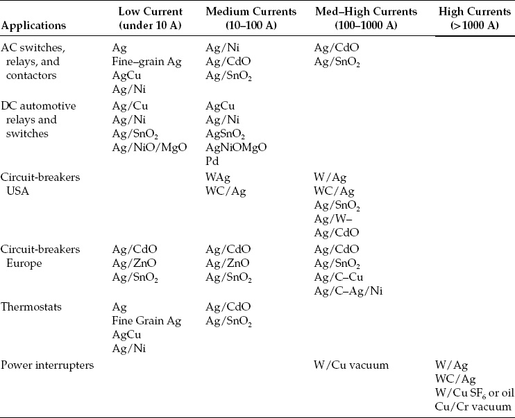
The author is very grateful to Dr. Zhuan-ke Chen, Chugai USA for technical discussions and Dr. Paul Slade discussions and suggestions. He also wants to thank the staff at Chugai USA: Sarah Bauer, Donna Witter, and Chris Anderson for their help in proofreading and editing.
1. G Rolland, Y Zerallil, V Guipoint, M Jeandin, S Hardy, L Doulet, C Bourda. Lifetime of cold-sprayed electrical contacts. Proc. 26th Int’l Conference on Electrical Contacts, 2012, pp 338–345.
2. Doduco Data Book of Electrical Contacts, Revised Edition, www.doduco.net, 2012.
3. Chugai USA Brochure, Chugai USA Inc., Waukegan, IL, 1995.
4. Umicore Brochure, Umicore, Brussels, Belgium.
5. American Society for Testing and Materials. ASTM Standards, Section 3, Metals Test Methods and Analytical Procedures, Vol. 03.04, 1987.
6. M Shen, W Cote, L Gould. A historic review of Ag–MeO materials. Proc. 32nd Holm Conference on Electrical Contacts, 1986, pp 71–76.
7. C Wagner. Zeitschrift fur Elektrochemie 63, 772–790, 1959.
8. E Freudiger, E Jost. Kinetics and thermodynamics of the internal oxidation of silver cadmium. Proc. 1st Int’l Research Symposium on Electrical Contact Phenomena, University of Maine, November 1961, pp 177–197.
9. J Grosse, T Moser, B Rothkegel. Internal oxidation of silver metallic oxide materials. Proc. 13th Int’l Conference on Electrical Contacts, 1986, pp 211–215.
10. E Jost, T Santala. Process and metallurgical variations affecting electrical performance of internally oxidized, homogeneous, monolithic silver cadmium oxide. Proc. 33rd IEEE-Holm Conference on Electrical Contacts, 1987, pp 175–179.
11. H Kim, T Peters. A metallurgical model of arc-erosion in Ag–CdO contacts. Proc. 22nd Holm Conference on Electrical Contacts, 1976, pp 98–97.
12. G Witter, Z Chen. Private research, Chugai Inc., USA, 1997.
13. D Pedder. Volatilisation of cadmium oxide and early welding in internally oxidized silver cadmium alloys. Proc. 23rd Holm Conference on Electrical Contacts, 1977, pp 69–76.
14. Shen Yuan-Shou, A Lima. Pure silver surface layer on the oxidized Ag–Sn–In material. Proc. 34th IEEE Holm Conference on Electrical Contacts, 1988, pp 13–15.
15. R German, Powder Metallurgaical Science, 2nd ed. Princeton, NJ: Metal Powder Industries Foundation, 1994.
16. ASM. Powder Metallurgy, Metals Handbook, Vol. 7, 9th ed. American Society of Metals, 1984.
17. T Allen. Particle Size Measurement, London: Chapman and Hall, 1968.
18. D Pedder, P Douglas, J McCarthy, F Brugner. I.O.A.P.—a novel process for the manufacturing of long-life silver–cadmium oxide AC contact materials. Proc. 22nd Holm on Electrical Contacts, 1976, pp 109–120.
19. M Fischmeister, G Grimvall. Oswald ripening—a survey, sintering and related phenomena. Material Science Research 6: 119, 1972.
20. A Lapinski. Investigations on the effect of technological parameters on the properties of fine grained Ag CdO sinter. Proc. 24th Holm Conference on Electrical Contacts, 1978, pp 201–208.
21. M Poniatowski. The influence of production method on the properties of contact materials for high current applications. Proc. 7th Int’l Conference on Electrical Contacts, 1974, pp 477–484.
22. M Poniatowski, K Schroder, E Schulz. Behavior at closing or opening of silver metallic oxide materials in electrical power engineering. Proc. 8th Int’l Conference on Electrical Contacts, 1976, pp 353–358.
23. M Poniatowski, E Schulz, A Wirths. The replacement of silver–cadmium oxide by silver–tin oxide low voltage switching devices. Proc. 8th Int’l Conference on Electrical Contacts, 1976, pp 359–364.
24. L Morin, N Ben Jemaa, D Jeannott, H Sone. Transition from the anodic arc phase to the cathodic metallic arc phase in vacuum at low DC electrical level. Proc. 47th IEEE Holm Conference 2001, pp 88–93.
25. N Ben Jemaa, L Morin, Transition from the anodic arc phase to the cathodic arc phase in vacuum at low DC electrical level, IEEE CPMT Trans, V25 Issue 4, Dec. 2002, pp 651–655.
26. G Witter, Z Chen. A comparison for the effects of opening speed, contact gap and material type on electrical erosion for relays interrupting inductive automotive loads. Proc. 23rd Int’l Conference on Electrical Contacts 2006, pp 17–21.
27. Z Chen, G Witter. A comparison of contact erosion for opening velocity variations for 13 volt circuits. Proc. 52nd IEEE Holm Conference 2006, pp 15–20.
28. F Heringhaus, P Braumann, A Koffler, E Susnik, R Wolmer, R Chaussee. Quantitative correlation of additive use and properties of Ag-SnO2-based contact materials. Proc. 21st Int’l Conference on Electrical Contacts 2002, pp 443–446.
29. E Hetzmannseder, W Rieder. Make erosion: Ag/MeO contact materials investigated in a contactor and in a new testing equipment. Proc. 16th Int’l Conference on Electrical Contacts, 1992, pp 371–377.
30. T Mützel, R Niederreuther. Advanced silver-tin oxide contact materials for relay application. Proc. 26th Intern’l Conference on Electrical Contacts, 2012, pp 194–199.
31. G Witter, I Polevoy. Contact erosion and material transfer for contacts in automotive relays. Proc. 18th Int’l Conference and 42nd IEEE Holm Conference on Electrical Contacts, 1996, pp 223–228.
32. G Witter, Z Chen. A comparison of silver tin indium oxide contact materials using a new model switch that simulates operation of automotive relays. I Proc.22nd Int’l Conference on Electrical Contacts, 2004, pp 382–387.
33. Z Chen, G Witter. Comparison in performance for silver-tin-indium oxide materials made by internal oxidation and powder metallurgy. Proc. 55th IEEE Holm Conference on Electrical Contacts, 2009, pp 180–186.
34. Z Chen, G Witter. A study of contact endurance switching life as a function of contact bond quality, contact electrical load and residual stresses for silver tin indium oxide composite rivet contacts. Proc. 58th IEEE Holm Conference on Electrical Contacts, 2012, pp 172–177.
35. D Susan et al., Very long term aging of 51 In-48 Sn (at.%) solder joints on Cu-plated stainless steel substrates, J Matter Sci 2009 44:545–555.
36. A Krätzchmar, R Herbst, T Mützel, R Niederreuther, P Braumann. Basic investigations on the behavior of advanced Ag/SnO2 materials for contactor applications. Proc. 56th IEEE Holm Conference on Electrical Contacts, 2010, pp 127–133.
37. F Hauner, D Jeannot, K McNeilly, Advanced AgSnO2 contact materaisls with high total oxide content. Proc. 21st Int’l Conference on Electrical Contacts, 2002 Zurich, pp 452–456.
38. H Francisco, M Myers. Optimization of silver tin oxide chemistry to enhance electrical performance in AC application. Proc. 44th IEEE Holm Conference on Electrical Contacts, 1998, pp 193–201.
39. A Shibata. Silver–metal oxide contact materials by internal oxidation process. Proc. 7th Int’l Conference on Electrical Contacts, 1974, pp 214–220.
40. B Gengenbach, K Jager, U Mayer, K Saeger. Mechanism of arc erosion on silver–tin oxide contact materials. Proc. 11th Int’l Conference on Electrical Contacts, 1982, pp 208–210.
@@@@41. N Behrens, W Bohm. Switching performance of different Ag/SnO2 contact materials made by powder metallurgy. Proc. 11th Int’l Conference on Electrical Contacts, 1982, pp 203–207.
42. B Gengenbach, U Mayer, R Michal, K Saeger. Investigations on the switching behavior of AgSnO2 materials in a commercial contactor. Proc. 12th Int’l Conference and 30th Holm Conference on Electrical Contacts, 1984, pp 243–247.
43. H Kim, F Reid. Development of improved Ag–CdO contact material by a reactive sintering process. Proc. 10th Int’l Conference on Electrical Contacts, 1980, pp 775–785.
44. F Brugner. An erosion resistant, lithium additive modified Ag–CdO. Proc. 9th Int’l Conference and 24th Holm Conference on Electrical Contacts, 1978, pp 191–195.
45. International Electrochemical Commission, Publication 158–159.
46. M Lindmayer, W Bohm. Effect of alkali on the switching behavior of Ag/CdO. Proc. 10th Int’l Conference on Electrical Contacts, 1980, pp 849–862.
47. K Jager, U Mayer, K Saeger. On the influence of small alkali additions on the switching behavior and materials properties of silver–cadmium oxide materials. Proc. 10th Int’l Conference on Electrical Contacts, 1980, pp 765–774.
48. International Electrotechnical Commission. Low-voltage switchgear and controlgear. Pub. CEI 947–4-1, First Edition, Geneva, Suisse, 1990.
49. R Kossowsky, P Slade. Effect of arcing on the microstructure and morphology of Ag–CdO Contacts. Proc. 6th Int’l Conference and Proc. 18th Holm Conference on Electrical Contacts, 1972, pp 117–127.
50. C Brecher, J Gustafson, T Peters. Spectroscopic study of erosion in Ag–CdO materials. Proc. 10th Int’l Conference on Electrical Contacts, 1980, pp 377–386.
51. C Brecher, J Gustafson. The effect of lithium upon the erosion kinetics of Ag–CdO contacts. Proc. 27th Holm Conference on Electrical Contacts, 1981, pp 83–88.
52. G Witter, M Lu. The effect of lithium additions and contact density for silver–cadmium oxide contacts for make and break arcs. Proc. 12th Int’l Conference and 30th Holm Conference on Electrical Contacts, 1984, pp 229–236.
53. J Schoepf, V Behrens, T Honig, A Kraus. Development of silver zinc oxide for general-purpose relays. Proc. 20th Int’l Conference on Electrical Contacts, 2000, pp 187–192.
54. Z Chen, G Witter. Development of cadmium-free contact material for AC wall switch applications. Proc. 23rd Int’l Conference on Electrical Contacts, 2006, pp 549–553.
55. V Behrens, T Honig, O Lutz, D Späth. Substitute contact material for silver/cadmium oxide in AC applications in the low current range. Proc. 23rd Int’l Conference on Electrical Contacts, 2006, pp 294–299.
56. D Sallais et al., New silver-oxide composites to reduce break arc duration and its subsequent damages. Proc. 23rd Int’l Conference on Electrical Contacts, 2006, pp 278–283.
57. C Leung, A Lee. Contact erosion in automotive DC relay. Proc. 15th Int’l Conference and 36th IEEE Holm Conference on Electrical Contacts, 1990, pp 85–93.
58. C Leung, A Lee. Electric contact materials and their erosion in automotive DC relays. Proc. 37th IEEE Holm Conference on Electrical Contacts, 1991, pp 114–121.
59. C Leung, A Lee. Silver tin oxide contact erosion in automotive relays. Proc. 39th IEEE-Holm Conference on Electrical Contacts, 1993, pp 61–67.
60. L Germer. Physical process in contact erosion. J Applied Phys 29: 1067–1082, 1958.
61. G Witter, Z Chen. Dynamic welding resistance comparisons of silver and silver metal oxides. Proc. 19th Int’l Conference on Electrical Contacts, 1998, pp 355–359.
62. Z Chen, G Witter. Dynamic welding of silver contacts under different mechanical bounce conditions. Proc. 45th IEEE Holm Conference on Electrical Contacts, 1999, pp 1–8.
63. Z Chen, G Witter. A study of dynamic welding of electrical contacts with emphasis on the effects of oxide content for silver tin indium oxide contacts. Proc. 56th IEEE Holm Conference on Electrical Contacts, 2010, pp 121–126.
64. A Neuhaus, C Schrank, M Reichart, and W Rieder. Influence of the break arc conditioning effect on make-arc welding and material transfer. Proc. 25th Int’l Conference on Electrical Contacts, 2006, pp 137.
65. A Erk, H Finke. Uber die mechanischen Vorgange wahrend des Preliens einschaltender Kontakte. ETZ-A 86 (1964b): 231–241, 1964.
66. M Ohta, S Matsuda, K Ogawa, A Shibata. New contact materials of silver–metal oxide system. Proc. 16th Int’l Conference on Electrical Contacts, 1992, pp 421–426.
67. K Schroder. Development of contact materials for power engineering in Europe. Proc. 33rd IEEE-Holm Conference on Electrical Contacts, 1987, pp 163–173.
68. K Schroder. Das Abbrandverhalten offnender Kontaktstucke bei Beanspruchung durch Magnetisch. Dissertation, TH Braunschweig, 1969.
69. K Schroder. Silver-metaloxides as contact materials. Proc. 13th International Conference on Electrical Contacts, 1986, pp 186–194.
70. H Manhart, W Rieder, C Veit. Arc mobility on new and eroded Ag/CdO and Ag/SnO2 contacts. Proc. 34th IEEE-Holm Conference on Electrical Contacts, 1988, pp 47–56.
71. F Brugner. The influence of Na and K impurities in Ag–CdO on the tendency for arc reignition during 600 VAC interruption by motor control gear. Proc. 23rd Holm Conference on Electrical Contacts, 1977, pp 77–79.
72. G Chen. The effect of Na, K, and Li on the arc interrupting capability of AgCdO contacts. Proc. 25th Holm Conference on Electrical Contacts, 1979, pp 199–204.
73. M Lindmayer. Effect of alkali additives on the reignition voltage of Ag/CdO. Proc. 25th Holm Conference on Electrical Contacts, 1979, pp 205–208.
74. P Braumann, K Schroder. Recovery of contact gaps with silver–metal-oxide contacts. Proc. 13th Int’l Conference on Electrical Contacts, 1986, pp 195–199.
75. B Gengenbach, U Mayer, G Horn. Erosion characteristics of silver based contact materials in a DC contactor. Proc. 12th Int’l Conference on Electrical Contacts, 1984, pp 201–207.
76. R German. Powder Metallurgical Science, 2nd ed. Princeton, NJ: Metal Powder Industries Foundation, 1994.
77. R Nelson, D Milner. Densification processes in the tungsten carbide–cobalt system. Powder Metallurgy 15 (30): 3, 1972.
78. G Gessinger, H Fischmeister, H Lukas. The influence of a partial wetting second phase on the sintering of solid particles. Powder Metallurgy 16 (31): 19, 1973.
79. M Hansen. Constitution of Binary Alloys, New York: McGraw-Hill, 1958.
80. Y Naidick, I Lavrinko, V Eremenka. The role of capillary phenomena in the densification process during sintering in the presence of the liquid phase. Powder Metallurgy 16 (31): 19, 1973.
81. Fansteel Inc., Make and Break. Contact brochure, Fansteel Inc., North Chicago, IL, 1971.
82. American Society for Metals. Metallography, Structures and Phase Diagrams, Vol. 8. Metals Park, OH: ASM, 1973.
83. G Witter. A correlation of material toughness, thermal shock resistance, and microstructure of high tungsten, tungsten–silver composite materials. Master of Science Dissertation, Illinois Institute of Technology, Chicago, 1975.
84. E Underwood. Quantitative Stereology. Reading, MA: Addison-Wesley, 1970.
85. J Gurland. The fracture strength of sintered tungsten carbide–cobalt alloy in relationship to composition and particle spacing. Trans. Metall. Soc. AIME 227: 1146, 1963.
86. K Stjernberg. Some relationships between the structure and mechanical properties of WC–Co alloys. Powder Metallurgy 13 (25): 1, 1970.
87. G Witter, W Warke. A correlation of material toughness, thermal shock resistance, and microstructure of high structure composite materials, Holm Conference on Electrical Contacts, IIT Chicago, IL, 1974, pp 238–249.
88. American Society For Testing Materials. Plane Strain Crack Toughness Testing Of High Strength Metallic Materials, STP No. 410, Philadelphia, PA: ASTM, 1966.
89. A. Evans. Fracture Mechanics of Ceramics, Vol. 1, Edited by Bradt R, et al., Plenum Publishing Co., New York, 1974.
90. P Slade. Arc erosion of tungsten based contact materials: a review. Refractory and Hard Metals 4(4): 208–214, 1986.
91. E Walczuk. Investigations of technical properties of Ag/W contact materials for the moulded case circuit breaker. Proc. 11th Int’l Conference on Electrical Contacts, 1982, pp 180–188.
92. C Leung, H Kim. A comparison of Ag/W, Ag/WC, and Ag/Mo electrical contacts. IEEE Trans. CHMT 7 (1): 69–75, 1984.
93. M Lindmayer, M Roth. Contact resistance and arc erosion of W/Ag and WC/Ag. Proc. 9th Int’l Conference on Electrical Contacts, 1978, pp 421–430.
94. H Turner, C Turner. Discontinuous contact erosion. Proc. 3rd Int’l Conference on Electrical Contacts, 1966, pp 309–320.
95. G Witter. The effect of nickel additions on the performance of tungsten silver materials. Proc. 11th Int’l Conference on Electrical Contacts, 1982, pp 351–355.
96. S Kabayama, M Koyama, M Kume. Silver–tungsten alloys with improved contact resistance. Powder Metallurgy International 5 (3): 122–126, 1973.
97. E Walczuk. Experimental study of Ag–W–Re composite materials under high current conditions. Proc. 32nd IEEE Holm Conference on Electrical Contacts, 1986, pp 77–83.
98. C Leung, D Harman, L Doublet, C Bourda, Y Cui, L Hu. Electrical and mechanical lives of Ag/C and Ag/WC/C contacts. Proc. 26th Int’l Conference on Electrical Contacts, 2012, pp 233–239.
99. S Allen, E Streicher, C Leung. Electrical performance of Ag-W-C and Ag-WC-C contacts in switching tests. Proc. 20th Int’l Conference on Electrical Contacts, 2000, pp 109–114.
100. T Browne, ed., Circuit Interruption, Theory and Design, New York: Marcel Dekker, 1984.
101. P Slade. Advances in material development for high power vacuum interrupter contacts. IEEE Trans. Components Packaging and Manuf Technol—Part A 17 (1): 96–106, 1994.
102. W Haufe, W Reichel, H Schreiner. Abbrand Verschiedener Wcu-Sinter-Trankwerkastoffe an Luft bei Hohen Stromen. A. Mettalde 63 (10): 651–654, 1972.
103. A Abdel-Asis. Neue Entwicklungen und Forschungen auf dem Gebiet der Schaltgeratetechnik. E.T.Z. Archiv 3 (9): 301–308, 1981.
104. I Zessak. Burn up behaviour of sintered contact materials tested repetitively at currents ranging from 400 A to 7000 A in oil. Proc. 9th Int’l Conference on Electrical Contacts, 1978.
105. F Labrenz. Erosion of switching electrodes by rotating arcs in SF6. Proc. 11th Int’l Conference on Electrical Contacts, 1982, pp 326–330.
106. J Kaminski. Burn-up behavior of nozzle electrodes with strong SF6 flow. Proc. 9th Int’l Conference on Electrical Contacts, 1978, p 25.
107. K Schroder. Das Abbrandverhalten offnender Kontaktstiicke bei Beanspruchung durch Magnetisch. Abgelenkte Starkstromlichtbogen. Thesis, TU Braunschweig, 1967.
108. A Keil, C Meyer. Uber die Bildung von isolierenden Deckschichten auf Kontakten aus Verbundmetallen. E.T.Z. 73 (2): 31–34, 1952.
109. P Slade, R Kossowsky. Effect of surface and contact resistance of a function of operating life in silver–tungsten contacts. Proc. 7th Int’l Conference on Electrical Contacts, 1974, pp 200–206.
110. G Witter, V Abele. The change in surface resistance of W–Ag contacts as a function of composition, microstructure, and environment. Proc. 8th Int’l Conference on Electrical Contacts, 1976, pp 445–451.
111. J Kosco. The effects of electrical conductivity and oxidation resistance on temperature rise of circuit breaker contact materials. Proc. 14th Holm Conference on Electrical Contacts, 1968, pp 55–66.
112. G Samsonov. The Oxide Handbook. New York: IFI/Plenum, 1973.
113. P Slade. Effect of the electric arc and the ambient air on the contact resistance of Ag, W, and W–Ag contacts. J Appl Phys 47 (8): 3438–3443, 1976.
114. H Kuhn, W Rieder. DerEinfluss natürlicher Hautschichten auf Konta. Stromen. Z. Metallde. 63 (10): 651–654, 1972.
115. P Slade. Variations in contact resistance resulting from oxide formation and decomposition in Ag–W and Ag–WC–C contacts passing steady currents for long times periods. IEEE Trans. Components, Hybrids and Manuf Technol CHMT-9 (1): 316, 1986.
116. C Leung, R Bevington, P Wingert, H Kim. Effects of processing methods on the contact performance parameters for silver–tungsten composite materials. IEEE Trans CHMT-5 (1): 23–31, 1982.
117. Hayashi et al. Surface-enhanced Raman scattering from layers of gas-evaporated silver small particles. J Applied Phys Part 1 28 (8): 1444–1449, 1989.
118. P Slade, C Lin, A Pebler. Titanium–tungsten carbide–silver, a new electric contact material. IEEE Trans. CHMT 4 (1): 76–84, 1981.
119. P Slade, C Lin, A Pebler, N Hoyer. The switching and short circuit performance of (Ti, W)C–Co–Ag and (Ti, W)C–Ag contacts. Proc. 11th Int’l Conference on Electrical Contacts, 1982, pp 189–193.
120. P Slade, Y Chien, J Bindas. Contact resistance variations in high silver content, silver-refractory carbide contacts. Proc. 13th Int’l Conference on Electrical Contacts, 1986, pp 216–220.
121. P Slade. High current contacts: A review and tutorial, 21st ICEC, Zurich, 2001, pp 413–424.
122. P Slade. The Vacuum Interrupter: Theory, Design, and Application, Boca Raton, FL: CRC Press, 2007.
123. W Li, P Slade, L Loud, R Haskins. Effect of Cu content on the electrical erosion of tungsten copper contacts switching load-current in vacuum. Proc. 48th Holm Conference on Electrical Contacts, 2002, pp 95–102.
124. E Taylor. Cathode spot behavior on tungsten-copper contacts in vacuum and the effect on erosion. Proc. 51st Holm Conference on Electrical Contacts, 2005, pp 135–138I.
125. F Hauner, G Tiefel, R Müller. CuCr for vacuum interrupters, properties and application. Proc. 24th Int’l Conference on Electrical Contacts, 2008, 61–68.
126. R Holm, E Holm. Electric Contacts Theory and Application. New York: Springer Verlag, 2000.
127. G Witter. Private Research.
128. H Wagar. Bell Telephone Laboratories. Physical Design Of Electronic Systems, Englewood Cliffs, NJ: Prentice-Hall, 1971, pp 439–594.
129. H Sone, H Ishida, T Takagi. Electrode temperature dependency on arc and erosion in electric contacts. Proc. 15th Int’l Conference on Electrical Contacts, 1990, pp 33–36.
130. V Behrens, R Michal, J Minkenberg, K Saeger, B Liang, W Zhang. Erosion mechanisms of different Ag/Ni 90/10 materials. Proc. 14th Int’l Conference on Electrical Contacts, 1988, pp 417–422.
131. W Balme, P Braumann, K Schroder. Welding tendency, contact resistance and erosion of contact materials in motor vehicle relays. Proc. 15th Int’l Conference on Electrical Contacts, 1990, pp 73–78.
132. K Sawa, M Hasegawa, K Miyachi. Contact characteristics of Ag and Pd contacts under various discharge conditions. Proc. 33rd IEEE Holm Conference on Electrical Contacts, 1987, pp 203–211.
133. T Tamai. Mechanisms of the low contact resistance properties for Ag-Pd-Mg contacts. Proc. 46th IEEE Holm Conference on Electrical Contacts, 2000, 94–101.
134. Z Chen, K Sawa. Polarity effect of unsymmetrical material combination on the arc erosion and contact resistance behaviour. Proc. 40th IEEE Holm Conference on Electrical Contacts, 1994, pp 79–88.
135. H Sone, I Hiroyuki, T Takagi. Electrode temperature dependency on arc and erosion in electric contacts. Proc. 15th IEEE Holm Conference on Electrical Contacts, 1990, pp 33–36.
136. C Hampel, Rare Metals Handbook 2nd Edition, New York: Reinhold, 1967.
137. Z Chen. Private Research, Chugai USA, Inc., Waukegan, IL, 1997.
138. P Wingert, S Allen, R Bevington. The effects of graphite particle size and processing on the performance of silver–graphite contacts. Proc. 37th IEEE Holm Conference on Electrical Contacts, 1991, pp 38–43.
139. K Muller, D Stockel. A new method for manufacturing of complex graphite-containing contact materials, Proc. 11th ICEC, 1982, pp 346–350.
140. M Lindmayer, K Schroder. The effect of unsymmetrical material combinations on the contact and switching behavior. Proc. 9th IEEE Holm Conference on Electrical Contacts, 1978, pp 265–271.
141. H Turner, C Turner. Polarity effects of silver/silver graphite contact combinations. Proc. 6th IEEE Holm Conference on Electrical Contacts, 1972, pp 351–356.
142. E Vinaricky, V Behrens. Switching behavior of silver/graphite contact material in different atmospheres in regard to contact erosion. Proc. 44th IEEE Holm Conference on Electrical Contacts, 1998, pp 292–300.