
Chapter 5. Domain model mapping
- Introducing the Entity Data Model
- Creating Entity Framework domain model classes
- Describing classes
- Describing database
- Mapping classes to database
So far, you’ve learned how to create an application from scratch, defining a model, mapping it to the database, and performing queries on it. We also looked at creating and mapping classes using the Visual Studio designer, which hides a lot of complexity, making your life easier. But a strong knowledge of the Entity Data Model and the code in the model classes is fundamental to mastering Entity Framework. In this chapter, we’ll dig deep into both subjects so that you’ll be able to completely understand this aspect of Entity Framework. This chapter covers the mapping of tables or views to entities. Other features, like stored procedures and function mappings, will be discussed in later chapters.
We’ll first look at the Entity Data Model, its concepts, and Microsoft’s vision about its future. After that, we’ll discuss how to create entities and map them. You’ll learn how to write an entity from scratch and create the three mapping files that allow you to map it to the database. You’ll see how Entity Framework 4.0 supports POCO (plain old CLR objects) entities and how this positively affects classes.
Once classes and their mapping are clear to you, we’ll create the association between them and describe everything in the Entity Data Model. You’ll finally learn how to create an inheritance hierarchy and how to reflect it into the Entity Data Model.
By the end of this chapter, you’ll have the knowledge to manually modify the mapping files where needed (because the designer isn’t all-powerful). When we talk about designer customization later, in chapter 13, this knowledge will help you a lot.
Let’s start by discussing what the Entity Data Model is and how it’s made.
5.1. The Entity Data Model
The Entity Data Model (EDM) is the heart of the Entity Framework. Essentially, Entity Framework is a tool that decouples the object model from the database by creating an abstraction layer between them. You develop an application that works with Entity Framework, which in turn works with the database. This means the application works only with the object model classes, ignoring the database. It’s the EDM that makes this decoupling possible.
You already know that the EDM is split into three sections:
- Conceptual schema (CSDL)—Describes the object model. Classes and their relationships have their counterparts in this section.
- Storage schema (SSDL)—Describes the database structure. Tables, views, and even stored procedures and functions are put into this section.
- Mapping schema (MSL)—Maps the CSDL and SSDL. Each class is mapped to one or more tables, and each property has a corresponding column.
The object model is the reflection of the CSDL, and they must be in sync. (Well, that’s not completely true. You can create properties in your object model class and avoid mapping them. They will be ignored by Entity Framework and won’t cause any problem.)
Now, you’re probably wondering at least two things:
- Where is the EDM?
- Is there any relationship between the EDM and the EDMX file used by the Visual Studio designer?
These questions will both be answered in the next section.
5.1.1. The Entity Data Model and Visual Studio designer
When you double-click the EDMX file in the Solution Explorer, Visual Studio opens the designer, showing entities. But to discover the relationship between the EDM and EDMX files, let’s follow another path. Right-click the EDMX file and select the Open With option, as shown in figure 5.1.
Figure 5.1. The context menu displayed when you right-click the EDMX file

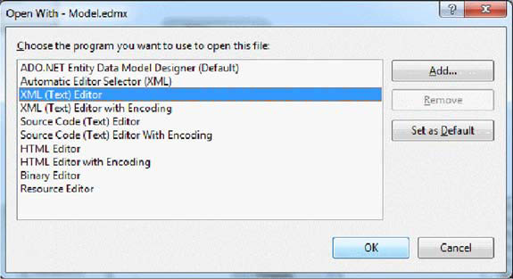
The designer opens the dialog box shown in figure 5.2. Select the XML (Text) Editor option, and click OK.
Figure 5.2. The Open With dialog box lets you open the EDMX file as an XML file instead of showing the designer.
Visual Studio will open a new window displaying an XML file that looks a lot like the EDM. (Note that if the designer is already open, you’ll be prompted about that. Click Yes to close the designer and open the new window.) The EDMX file contains the three EDM files plus other information used by the designer, like the positions of the objects on the canvas, the zoom, the scroll position, and so on.
Note
The fact that EDM and designer data are mixed causes problems when working in teams. If one person works on the Customer and Supplier classes, he probably optimizes his view of the designer to see those entities. Someone else who works on the products will optimize her view for those classes. Each time the EDMX is checked in, it overrides the previous view. This problem will be solved in the future, using separate files: one for the EDM, shared by everyone; and one for the designer data, which can be kept out of source control.
You can see the collapsed EDMX file in figure 5.3.
Figure 5.3. A collapsed view of the EDMX file. The Runtime section contains the EDM, and the Designer section contains the designer-related information.
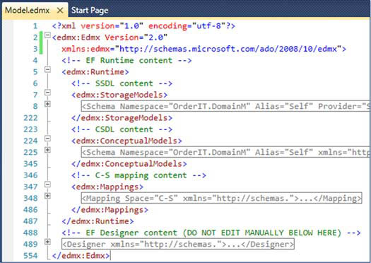
The EDM is under the edmx:Edmx/edmx:Runtime path. Inside it, you can see the storage, conceptual, and mapping schemas. The designer-related information is stored in the edmx:Edmx/edmx:Designer path. For our discussion, the designer info isn’t important, so we’ll ignore it.
The EDMX file is an artifact—it’s necessary to create the designer in Visual Studio. Entity Framework isn’t interested at all in the EDMX file—it can’t even parse it. Entity Framework only understands mapping files when they’re split into three: one for the conceptual schema (*.csdl), one for the storage schema (*.ssdl), and one for the mapping schema (*.msl).
If you look at the metadata attribute of the connection string, you’ll see a reference to the three mapping files:
metadata=res://*/OrderIT.csdl|res://*/OrderIT.ssdl|res://*/OrderIT.msl
metadata=c:OrderIT.csdl|c:OrderIT.ssdl|c:OrderIT.msl
The EDMX file contains the EDM, but Entity Framework doesn’t understand it. The connection string references three mapping files that are nowhere in the project: how does this work? The answer is that at compile time, the designer extracts the sections from the EDMX file and creates a separate file for each one.
These files are either embedded into the assembly or copied into the output directory. You can specify which by opening the designer properties and setting the Metadata Artifact Processing property to either Embed in Output Assembly or to Copy to Output Directory. The setting names are self-explanatory.
Now that you know the basics of the EDM and how it integrates with Visual Studio, you’re ready to create and map models. The first thing you need to do when creating a model is design the entities. Designing a class is the same as writing, or creating, it.
5.2. Creating consumable entities
When the designer generates code to create entities, it performs the following steps:
1. Create the entity’s code.
2. Create the conceptual schema.
3. Create the storage schema.
4. Create the mapping schema.
In the next sections, you’ll manually perform these steps to reproduce the tables and entities involved in OrderIT’s ordering process and see how mapping works under the covers.
Note
By default, the designer emits Entity Framework–aware non-POCO code—a choice that was made to maintain compatibility with the previous release. With Entity Framework 4.0, it’s pointless using non-POCO code. We strongly recommend always using the POCO template that we introduced in chapter 2.
Let’s start with the first step.
POCO (plain old CLR object) classes lead to persistence ignorance (PI). PI allows the user to write code that only cares about the business problem without any infrastructure intrusion. The Order and OrderDetail classes know nothing about Entity Framework. The persistence engine could be a handwritten data layer, Entity Framework, NHibernate, or something else. What’s more, a clean separation between the object model classes and the persistence engine allows you to put the classes in the model assembly (the object model or domain model, depending on your architecture), leaving to the infrastructure or the data layer (again, depending on the architecture) the burden of persistence. More separation leads to more maintainability; more maintainability leads to better reactions to application changes and bugs; better reactions lead to happier customers and lower costs; and all of this leads to a great success.
Nonetheless, don’t be deceived by PI. It’s not always needed. We have shipped many projects using Entity Framework 1.0 without worrying about PI. Those projects were well designed and efficient, and the customer is happy with them. PI is important and sometimes would have saved hundreds of lines of code, but it’s not the only key to a winning project.
5.2.1. Writing the entities
The ordering process in OrderIT includes the Order and OrderDetail entities plus the AddressInfo complex type. Thanks to the POCO support, you can create such classes without worrying about persistence (as you’ll notice in listing 5.1). For now, let’s forget about associations. We’ll discuss them later.
Listing 5.1. Creating the order scenario model
C#
public class AddressInfo
{
  public virtual string Address { get; set; }
  Public virtual string ZipCode { get; set; }
  Public virtual string City { get; set; }
  Public virtual string Country { get; set; }
}

public class Order
{
  public virtual int OrderId { get; set; }
  public virtual DateTime OrderDate { get; set; }
  public virtual AddressInfo ShippingAddress { get; set; }
  public virtual DateTime EstimatedShippingDate { get; set; }
  public virtual DateTime ActualShippingDate { get; set; }
}

public class OrderDetail
{
  public virtual int OrderDetailId { get; set; }
  public virtual int Quantity { get; set; }
  public virtual decimal Price { get; set; }
  public virtual decimal Discount { get; set; }
}
VB
Public Class AddressInfo
  Public Overridable Property Address as String
  Public Overridable Property ZipCode as String
  Public Overridable Property City as String
  Public Overridable Property Country as String
End Class

Public Class Order
  Public Overridable Property OrderId as Int32
  Public Overridable Property OrderDate as DateTime
  Public Overridable Property ShippingAddress as AddressInfo
  Public Overridable Property EstimatedShippingDate as DateTime
  Public Overridable Property ActualShippingDate as DateTime
End Class

Public Class OrderDetail
  Public Overridable Property OrderDetailId as Int32
  Public Overridable Property Quantity as Int32
  Public Overridable Property Price as Decimal
  Public Overridable Property Discount as Decimal
End Class
That’s all you need to create the entities. Isn’t it great? It’s 19 lines of code, and you’re done. In Entity Framework 1.0, it would have taken about 70 lines. That’s a huge step ahead.
Complex properties deserve more attention. When you instantiate Order, the address is null because it isn’t created anywhere. This means that you should create the address every time you create an order, and that’s repetitive and error-prone code.
You have two options for solving this problem: instantiate the address in the order constructor, or instantiate it lazily when it’s accessed for the first time. Both options are shown in listing 5.2.
Listing 5.2. Two ways of instantiating complex properties

The constructor solution requires less code, so it’s our favorite, but we have nothing against lazy instantiation. The result is the same, and the choice is up to you.
There is another step we skipped: the overriding of Equals and GetHashCode. When you create a model, implementing them for each class is important. There’s lots of literature out there about how to best implement these methods, so we won’t explain it here. Our suggestion is to write them as follows.
Listing 5.3. Implementing Equals and GetHashCode in the Order entity
C#
public class Order
{
  ...
  public override bool Equals(object obj)
  {
    Order order = obj as Order;
    if (order == null) return false
    return order.OrderId == this.OrderId;
  }

  public override int GetHashCode()
  {
    return OrderId.GetHashCode();
  }
}
VB
Public Class Order
  ...
  Public Overloads Overrides Function Equals(ByVal obj As Object)
    As Boolean
    Dim order As Order = TryCast(obj, Order)
    If order Is Nothing Then
      Return False
    End If
    Return order.OrderId = Me.OrderId
  End Function

  Public Overloads Overrides Function GetHashCode() As Integer
    Return OrderId.GetHashCode()
  End Function
End Class
This code says that two orders are equal if their OrderId property has the same value.
In chapters 2 and 3, you were introduced to the runtime proxy subject. You learned that in order to be runtime extensible, a class must be open to inheritance and all properties must be virtual/Overridable. You can avoid these rules, but the obtained objects wouldn’t provide features like object tracking and lazy loading. Because they’re important in many scenarios, we always suggest making properties virtual.
Note
It’s important that you understand how to create classes. You may need to customize entity code generation to accommodate particular needs (as we’ll do in chapter 13). This means that an understanding of classes is at least desirable.
The classes created in this section aren’t consumable by Entity Framework yet. You must put the necessary information into the EDM. The starting point for doing this is the conceptual file.
5.2.2. Describing entities in the conceptual schema
The conceptual schema contains the description of the entities. Creating this schema isn’t difficult at all, but because many XML tags are involved, you might find it confusing at first. Fortunately, these tags are reused in the storage schema, significantly simplifying the entire EDM.
In the EDMX file for OrderIT, the conceptual schema is at the path edmx:Edmx/edmx:Runtime/edmx:ConceptualModels. If you create the conceptual file manually, you can name it OrderIT.csdl and reference it in the database connection string. In the CSDL file, you must ignore the preceding XML path because it’s part of the EDMX artifact. This applies also to the storage and the mapping files.
The basic structure of the CSDL is pretty simple. It has a main element named Schema, inside which there is an EntityContainer element plus an EntityType for each entity and a ComplexType for each complex type. Figure 5.4 shows the file structure.
Figure 5.4. The structure of the CSDL file. Schema is the main element, and EntityContainer, ComplexType, and EntityType are its children.

Having a broad understanding of the structure is good, but knowing each node is essential to mastering mapping. Let’s analyze them one by one, starting from the outermost: Schema.
Schema
Schema is a pretty simple element. It contains the attributes Namespace and Alias to specify the namespace and an alias for it. Furthermore, it declares the base namespace via xmlns and an additional namespace with the store prefix:
<Schema xmlns="http://schemas.microsoft.com/ado/2008/09/edm"
xmlns:store="http://schemas.microsoft.com/ado/2007/12/edm/EntityStoreSchemaGenerator" Namespace="OrderITModel" Alias="Self">
  ...
</Schema>
Because Schema is a mere container, there is nothing special about its attributes. What we’re more interested in is its inner content.
Entitycontainer
The EntityContainer element declares the entity sets and the relationship sets in the EDM; the entity sets declared here are used to generate the code of the context class. The element has only a Name attribute, which the designer sets to the name of the connection string you enter in the EDMX wizard. If you create the file manually, we suggest setting the attribute value to the name of the application, plus the suffix Entities.
If you look at the context-generated code, you’ll see that all base constructors take a ContainerName argument. That argument is the container name as inserted in the EDM, so the context is linked with its description in the EDM.
Note
You can have many EntityContainer tags, which means you can have many contexts. This may be useful when you want to logically separate different parts of your application. It’s not supported by the designer, but you can do it if you want to edit files manually.
As you may expect, the EntityContainer is a mere wrapper. Inside it is one Entity-Set element for each entity set. You learned in chapter 2 that there’s an entity set for each class that doesn’t inherit from another one in the model. For instance, Order has an entity set, and Company has an entity set, but Supplier and Customer don’t because they inherit from Company.
EntitySet has two attributes:
- Name declares the entity set’s unique name. (In chapter 2, you set the entity set name for each entity in the designer—that value was put into the Name attribute.)
- EntityType contains the fully qualified name (FQN) of the entity it exposes.
In the end, the entity container looks like the following listing.
Listing 5.4. Defining the entity sets in EntityContainer
<EntityContainer Name="OrderITEntities">
  <EntitySet Name="Orders" EntityType="OrderIT.DomainModel.Order" />
  <EntitySet Name="OrderDetails"
    EntityType="OrderITModel.OrderDetail" />
</EntityContainer>
You can define multiple entity sets for a single type. This feature is named multiple entity sets per type (MEST), and it may be extremely useful in some scenarios. Suppose you’re developing a site that handles articles, blog posts, and forum posts. These items share the same structure: a posted date, a published date, text, a subject, and so on. They may be stored in different tables, but a single class represents them.
MEST allows you to reuse one class across different entity sets. Unfortunately, this approach has limitations when dealing with associations, and, what’s worse, it isn’t supported by the designer, so you have to create the class’s code and mapping manually. In the end, MEST slows down productivity, so unless you have a strong reason to use it, don’t.
Now that you understand the EntityContainer, we can move on to the model classes. The element that describes an entity is EntityType, whereas a complex type is represented by ComplexType.
Complextype and Entitytype
ComplexType has only the Name attribute, which is set to the class FQN. Inside it is one Property node for each property of the complex type. Property has several attributes, which are described in table 5.1.
Table 5.1. Attributes of Property node in the conceptual schema
|
Description |
Required |
|
|---|---|---|
| Name | Specifies the name of the property. | Yes |
| Type | Specifies the CLR type of the property. If the property is a complex type, this should be set to the FQN of the complex type. | Yes |
| Nullable | Indicates whether the property can be null. The default value is true. | No |
| FixedLength | Indicates whether the property must have a fixed length. | No |
| MaxLength | Specifies the maximum length of the value. | No |
| Scale | Specifies how many numbers are allowed after a comma in a decimal type. | No |
| Precision | Specifies how many numbers are allowed in a decimal type. | No |
| store:StoreGeneratedPattern | Indicates how the column is set by the database during inserts and updates. It has three possible values:
|
No |
| ConcurrencyMode | Indicates whether the property participates in the concurrency check. To enable the check, set the value to Fixed. | No |
When the complex type is ready, you can start creating entities that use it. EntityType is where you do this. It has a mandatory Name attribute, where the name of the class is specified. After that, there are two optional attributes:
- Abstract—Specifies whether the class is abstract
- BaseType—Specifies a base class
Abstract and BaseType become important when inheritance comes into play. (We’ll get to inheritance in section 5.4.)
Inside EntityType is a Property element for each scalar and complex property in the class, and a Key element to specify which properties are in the entity’s primary key. If the property is a complex property, you set its type to the full name of the complex type it represents through the Type attribute. The Key element has no attributes; it has only one PropertyRef node for each property that participates in the primary key. PropertyRef has only the Name attribute, which contains the name of the property.
Putting everything in action, the mapping fragment looks like this.
Listing 5.5. Describing complex types and entities
<ComplexType Name="AddressInfo">
  <Property Type="String" Name="Address" Nullable="false" MaxLength="50" />
  <Property Type="String" Name="City" Nullable="false" MaxLength="50" />
  <Property Type="String" Name="ZipCode" Nullable="false" MaxLength="15" />
  <Property Type="String" Name="Country" Nullable="false" MaxLength="30" />
</ComplexType>
<EntityType Name="Order">
  <Key>
    <PropertyRef Name="OrderId" />
  </Key>
  <Property Type="Int32" Name="OrderId" Nullable="false"
    store:StoreGeneratedPattern="Identity" />
  <Property Name="ShippingAddress" Type="OrderITModel.AddressInfo"
    Nullable="false" />
  <Property Type="DateTime" Name="EstimatedShippingDate" Nullable="false"
    Precision="29" />
  <Property Type="DateTime" Name="ActualShippingDate" Nullable="false"
    Precision="29" />
</EntityType>
<EntityType Name="OrderDetail">
  <Key>
    <PropertyRef Name=" OrderDetail Id" />
  </Key>
  <Property Type="Int32" Name="OrderDetailId" Nullable="false"
    store:StoreGeneratedPattern="Identity" />
  <Property Type="Int16" Name="Quantity" Nullable="false" />
  <Property Type="Decimal" Name="UnitPrice" Nullable="false" Precision="29"
    Scale="29" />
  <Property Type="Decimal" Name="Discount" Nullable="false" Precision="29"
    Scale="29" />
</EntityType>
That’s all you need to know about the conceptual schema, but that’s only the first part of the EDM. You still have to create the storage schema to describe the tables that will persist orders and their details. Later, you’ll bridge the two models in the mapping file.
5.2.3. Describing the database in the storage schema
The storage-description file contains detailed information about the database structure. You can map several database objects here: tables, views, stored procedures, and functions. In this chapter, we’ll focus on the first two objects only; the others will be discussed in chapter 10, which is dedicated to the use of stored procedures.
In the EDMX file for the OrderIT example, the storage schema is under the edmx:Edmx/edmx:Runtime/edmx:StorageModels path; but if you want to create the file manually, you can name it OrderIT.ssdl and reference it in the connection string.
We already mentioned that conceptual schema elements are reused in the storage schema. This is true, but some nodes have more attributes in the storage schema to accommodate specific database options. Let’s start by looking at the Schema node.
Schema
Schema is the root element of the storage schema. It has the same attributes as its counterpart on the conceptual side, plus two needed for database communication:
- Provider—Specifies the ADO.NET provider
- ProviderManifestToken—Specifies the version number of the database (for instance, SQL Server uses 2000, 2005, and 2008)
The following snippet contains an example of the Schema element:
<Schema Namespace="OrderITModel.Store" Alias="Self"
  Provider="System.Data.SqlClient" ProviderManifestToken="2008"
  xmlns:store="http://schemas.microsoft.com/ado/2007/12/edm/EntityStoreSchemaGenerator"
  xmlns="http://schemas.microsoft.com/ado/2009/02/edm/ssdl">
  ...
</Schema>
As in the conceptual file, Schema has both a container section and a detail section. You’ll be happy to know that the container section is named the same way it is in the conceptual file.
Entitycontainer
EntityContainer declares all database objects described later in the file. Its only attribute is Name, which represents the name of the container. The designer sets its value to the namespace name plus the suffix StoreContainer. Although you can have multiple EntityContainer elements in the conceptual schema, that’s nonsense in the storage schema, because the objects belong to a single database.
Inside EntityContainer, you create an EntitySet element for each table or view. EntitySet in the storage schema has more attributes than its counterpart on the conceptual side:
- Name—Specifies the logical name of the object. The designer uses the name of the table, but it’s not mandatory.
- EntityType—Represents the FQN of the object and is set using the {namespace}.{name} pattern.
- Schema—Represents the owner of the table.
- Table—Represents the physical name of the table. Table isn’t mandatory; when it’s omitted, Name is used.
- store:Type—Identifies whether the object is a table (Tables) or a view (Views).
The result is the fragment shown here.
Listing 5.6. Defining database tables and views
<EntityContainer Name="OrderITModelStoreContainer">
  <EntitySet Name="Order" EntityType="OrderITModel.Store.Order"
    store:Type="Tables" Schema="dbo" />
  <EntitySet Name="OrderDetail"
    EntityType="OrderITModel.Store.OrderDetail"
    store:Type="Tables" Schema="dbo" />
</EntityContainer>
We’ve introduced a bunch of new attributes, and you’ve reused all the previous elements and declared the database objects. This is a successful case of code reuse. Now you need to describe the table structure.
Entitytype
Objects are described using the EntityType element, much as in the conceptual file. You must create one element for each EntitySet element that’s put inside Entity-Container. In the conceptual file, classes that are part of an inheritance hierarchy have only one EntitySet but many EntityType elements. Databases don’t support inheritance natively, so it isn’t possible to have one entity set and more tables or views in the storage file.
Every EntityType node has a Name attribute whose value must match the Name attribute of the EntitySet in the entity container.
Inside the EntityType element, you have to include the elements that describe the database object. Again, you use Property to declare the columns and Key and PropertyRef to specify which ones compose the key.
Property has the same attributes as its counterpart in the CSDL, plus some additional ones to accommodate database needs:
- Collation—Specifies the collation of the column
- DefaultValue—Specifies the default value of the column
- Unicode—Specifies whether the value is Unicode
The result is the mapping fragment shown in the following listing.
Listing 5.7. Describing the Order and OrderDetail database tables
<EntityType Name="Order">
  <Key>
    <PropertyRef Name="OrderId" />
  </Key>
  <Property Name="OrderId" Type="int" StoreGeneratedPattern="Identity"
    Nullable="false" />
  <Property Name="ShippingAddress" Type="nvarchar" Nullable="false"
    MaxLength="50" />
  <Property Name="ShippingCity" Type="nvarchar" Nullable="false"
    MaxLength="50" />
  <Property Name="ShippingZipCode" Type="nvarchar" Nullable="false"
    MaxLength="15" />
  <Property Name="ShippingCountry" Type="nvarchar" Nullable="false"
    MaxLength="30" />
  <Property Name="EstimatedShippingDate" Type="datetime" Nullable="false"/>
  <Property Name="ActualShippingDate" Type="datetime" Nullable="false" />
  <Property Name="CustomerId" Type="int" Nullable="false" />
</EntityType>
<EntityType Name="OrderDetail">
  <Key>
    <PropertyRef Name="OrderDetailId" />
  </Key>
  <Property Name="OrderDetailId" Type="int"
    StoreGeneratedPattern="Identity" Nullable="false" />
  <Property Name="Quantity" Type="smallint" Nullable="false" />
  <Property Name="UnitPrice" Type="decimal" Nullable="false" Precision="29"
    Scale="29" />
  <Property Name="Discount" Type="decimal" Nullable="false" Precision="29"
    Scale="29" />
  <Property Name="OrderId" Type="int" Nullable="false" />
  <Property Name="ProductId" Type="int" Nullable="false" />
</EntityType>
The storage file is now ready. You’re only missing the link between the conceptual and storage schemas. You already know that this bridge is created using the third file of the EDM: the mapping schema.
5.2.4. Creating the mapping file
The mapping file has the hard duty of bridging the gap between database and classes. When the model has one class for each table, the mapping is pretty simple; but as soon as things get more complicated, the mapping becomes complex.
In the EDMX file for the OrderIT example, edmx:Edmx/edmx:Runtime/edmx:Mappings is the path of the mapping section. If you want to create the file on your own, you can create OrderIT.msl and reference it in the connection string.
The mapping file doesn’t describe entities or tables—it maps them. As a result, this file’s structure is completely different from the other two files. Unfortunately, this means you have to learn a bunch of new XML tags and attributes, as you can see in figure 5.5.
Figure 5.5. The main structure of the mapping file

Differences emerge immediately at the root level. Although Schema is the root element for the conceptual and storage files, here you use Mapping.
Mapping and Entitycontainermapping
The declaration of the Mapping node is fixed, and you can’t put any custom information in it. The only inner element it allows is EntityContainerMapping, where you specify the name of the containers whose entities must be mapped. (You have to specify the containers because you map entities and complex types used by the entity sets.) The StorageEntityContainer attribute identifies the storage schema container, and the CdmEntityContainer attribute is used for the conceptual schema container, as you can see in listing 5.8.
Listing 5.8. Defining the containers in the mapping
<Mapping Space="C-S"
  xmlns="http://schemas.microsoft.com/ado/2008/09/mapping/cs">
  <EntityContainerMapping CdmEntityContainer="OrderITEntities"
    StorageEntityContainer="OrderITModelStoreContainer">
    ...
  </EntityContainerMapping>
</Mapping>
After the entity containers are linked, the next step is to map tables and views against classes. This is accomplished by nesting an EntitySetMapping element inside the EntityContainerMapping element for each entity set.
Entitysetmapping, Entitytypemapping, and Mappingfragment
Mapping an entity to a table is a four-step job. You start by defining the entity set and the entity inside it. Within the entity, you specify the table to which the entity is mapped, and finally you specify the column/property association between the two. Figure 5.5 shows the elements that must be used in the process.
EntitySetMapping is the node that lets you state what entity set you’re going to map (remember that you can have multiple classes per entity set). The only attribute here is Name, and it’s used to specify the entity set name.
Inside EntitySetMapping, you nest an EntityTypeMapping element for each entity that’s part of the entity set. The type of the entity is set through the TypeName attribute and must follow the pattern IsTypeOf(EntityName), where EntityName is the FQN of the entity.
Now we come to the mapped tables. Because a class can be mapped to one or more tables (Order maps to the Order table, but Shirt maps to both the Product and Shirt tables), inside the EntityTypeMapping element you specify a MappingFragment element for each table involved. It has only the StoreEntitySet attribute, and it must match the Name attribute of the entity set in the storage schema. The next listing shows this first part of the mapping.
Listing 5.9. Defining the entity set, the class, and the mapped table
<EntitySetMapping Name="Orders">
  <EntityTypeMapping TypeName="IsTypeOf(OrderITModel.Order)">
    <MappingFragment StoreEntitySet="Order">
      ...
    </MappingFragment>
  </EntityTypeMapping>
</EntitySetMapping>
<EntitySetMapping Name="OrderDetails">
  <EntityTypeMapping TypeName="IsTypeOf(OrderITModel.OrderDetail)">
    <MappingFragment StoreEntitySet="OrderDetail">
      ...
    </MappingFragment>
  </EntityTypeMapping>
</EntitySetMapping>
Now you have the entity set, the class, and the table (or tables). That’s all you need to start the property-to-column mapping process. In the next section, you’ll see how this delicate part works.
Scalarproperty and Complexproperty
The ScalarProperty element maps a scalar property of the class to a column of the table or view. It has only two attributes:
- Name—Represents the property name
- ColumnName—Represents the mapped column
Easy as pie.
ComplexProperty is used to map a complex type. This node has two attributes too:
- Name—Specifies the name of the property in the class
- TypeName—Contains the FQN of the complex type
ComplexProperty on its own is useless. You have to map its properties to the columns, and this is done by nesting ScalarProperty elements.
Note
Because complex types can be nested, you can put a Complex-Property inside another ComplexProperty.
Putting it all together, the following listing shows the overall mapping schema for Order and OrderDetail.
Listing 5.10. Defining the mapping between properties and columns
<EntitySetMapping Name="Orders">
  <EntityTypeMapping TypeName="IsTypeOf(OrderITModel.Order)">
    <MappingFragment StoreEntitySet="Order">
      <ScalarProperty Name="Id" ColumnName="Id" />
      <ComplexProperty Name="ShippingAddress"
        TypeName="OrderITModel.AddressInfo">
        <ScalarProperty Name="Address" ColumnName="ShippingAddress" />
        <ScalarProperty Name="City" ColumnName="ShippingCity" />
        <ScalarProperty Name="ZipCode" ColumnName="ShippingZipCode" />
        <ScalarProperty Name="Country" ColumnName="ShippingCountry" />
      </ComplexProperty>
      <ScalarProperty Name="EstimatedShippingDate"
        ColumnName="EstimatedShippingDate" />
      <ScalarProperty Name="ActualShippingDate"
        ColumnName="ActualShippingDate" />
    </MappingFragment>
  </EntityTypeMapping>
</EntitySetMapping>
<EntitySetMapping Name="OrderDetails">
  <EntityTypeMapping TypeName="IsTypeOf(OrderITModel.OrderDetail)">
    <MappingFragment StoreEntitySet="OrderDetail">
      <ScalarProperty Name="Id" ColumnName="Id" />
      <ScalarProperty Name="Quantity" ColumnName="Quantity" />
      <ScalarProperty Name="UnitPrice" ColumnName="UnitPrice" />
      <ScalarProperty Name="Discount" ColumnName="Discount" />
    </MappingFragment>
  </EntityTypeMapping>
</EntitySetMapping>
So far, we have covered entities and ignored the associations between them, but associations between entities are the real essence of a model. Mapping them isn’t too complicated, but you still have to touch all three EDM schemas. Fortunately, you know something about the schemas, so it should be simpler.
5.3. Defining relationships in the model
Implementing associations is one of the most challenging tasks in any O/RM, but the Entity Framework makes it quite easy. Naturally, you’ll have to write some code and modify the mapping, but you’ll understand it at first sight.
In the OrderIT model, there are three types of associations: one-to-one, one-to-many, and many-to-many. Let’s look at them in turn.
5.3.1. One-to-one relationships
A typical example of a one-to-one relationship is that between the order detail and its order. Creating this type of association isn’t difficult, but it involves several steps:
1. Modify the OrderDetail class by adding the navigation property. If you opt for foreign-key associations (as we did), you’ll have to add the foreign-key property too.
2. Modify the CSDL to add properties to the class description and introduce the relationship.
3. Modify the storage schema to introduce the foreign key between the tables (if it exists).
4. Modify the mapping schema to map the relationship (only for independent associations).
Now, let’s look at each step.
Modifying the Class
To create a reference to the order from the order detail, you need to create an Order property in the OrderDetail class. Because you’re using foreign keys, you have to add a foreign key property, as shown in the next listing.
Listing 5.11. Creating properties that reference the order from the order detail
public class OrderDetail
{
  ...
  public virtual Order Order { get; set; }
  public virtual int OrderId { get; set; }
}
VB
Public Class OrderDetail
  ...
  Public Overridable Property Order() As Order
  Public Overridable Property OrderId() As Integer
End Class
That’s all you need to do to create the relationship in the code. All the plumbing that was necessary to create associations in the classes in v1.0 is gone. Lovely!
Now that the code is fine, let’s get back to the EDM and look at the conceptual schema.
Modifying the Conceptual Schema
Because the conceptual schema describes the model, this is where you must add information about the new properties and the relationship. You need to add the new navigation and foreign-key properties to the OrderDetail entity description.
The navigation property is added to the EntityType node related to OrderDetail by using the NavigationProperty element. The Name attribute maps the element to the property in the object, Relationship requires the full name of the relationship, FromRole identifies its starting point, and ToRole identifies the ending point. In this way, you can move from OrderDetail to Order.
The foreign-key property is added as a simple scalar property. Both properties are shown here.
Listing 5.12. Adding navigation and foreign-key properties to the entity in the CSDL
<EntityType Name="OrderDetail">
  ...
  <NavigationProperty Name="Order"
    Relationship="OrderIT.Domain.OrderOrderDetail" FromRole="OrderDetail"
    ToRole="Order" />
  <ScalarProperty Name="OrderId" ColumnName="OrderId" />
</EntityType>
That’s all you need to do for the entity description. Now, let’s move on to the relationship description. In Entity Framework, associations are first-class citizens, like entities, so they must be treated equally in the EDM.
In the EntityContainer element, you need to declare an AssociationSet for each association. It has two attributes:
- Name—Represents the name of the relationship set (a sort of entity set for associations)
- Association—Specifies the type
Inside AssociationSet, you insert two End nodes (one for each entity involved), placing the name of the class in the Role attribute and the name of its entity set in EntitySet.
Note
When you use the designer, the Name attribute is set with the name you assign to the relationship in the Association wizard.
Outside EntityContainer, you need to describe the relationship using the Association element. Its Name attribute links the description to the AssociationSet in the container, whereas the nested End elements describe the types involved in the relationship and their cardinality. What’s important in the End element is the Multiplicity attribute, which can have one of the following values:
- 1—One side of the cardinality
- 0..1—Zero or one side of the cardinality
- *—Multiple side of the cardinality
End allows you to specify the delete cascade behavior. This has nothing to do with the database; it states that when the parent entity is marked as deleted, children are marked too. Its definition in the mapping is shown in the following listing.
Listing 5.13. Declaring and defining associations
<EntityContainer ...>
  <AssociationSet Name="OrderOrderDetail"
    Association="OrderITModel.OrderOrderDetail">
    <End Role="Order" EntitySet="Orders">
      <OnDelete Action="Cascade" />
    </End>
    <End Role="OrderDetail" EntitySet="OrderDetails" />
  </AssociationSet>
</EntityContainer>

<Association Name="OrderOrderDetail">
  <End Role="Order" Type="OrderITModel.Order" Multiplicity="1" />
  <End Role="OrderDetail" Type="OrderITModel.OrderDetail"
    Multiplicity="*" />
</Association>
Order is the one side, and OrderDetail is the multiple side in this example. That means you’re mapping a one-to-many relationship! A one-to-many relationship implicitly declares the one-to-one relationship too. The order can have multiple details, but a detail can have only one order. It would be useless repeating this relationship twice in the EDM, so you declare it only once.
An independent association is mapped in the MSL, but a foreign-key association is mapped in the CSDL. Because we’ve opted to use a foreign-key relationship in this example, you have to add mapping information to the association definition. This information is put in the ReferentialConstraint node inside the Association element, and it comes after the End nodes, as shown in the next listing.
Listing 5.14. Defining a foreign-key association
<Association Name="OrderOrderDetail">
  ...
  <ReferentialConstraint>
    <Principal Role="Order">
      <PropertyRef Name="OrderId" />
    </Principal>
    <Dependent Role="OrderDetail">
      <PropertyRef Name="OrderId" />
    </Dependent>
  </ReferentialConstraint>
</Association>
ReferentialConstraint is only the container element. The real mapping happens in the Principal and Dependent nodes, where you specify the primary key of the master class and the foreign-key property in the child class (through the PropertyRef element). It’s much like defining a foreign key in a database.
The conceptual schema is now ready; the third step is modifying the storage. But wait a second; what if the database knows nothing about the relationship between the order and its details? The foreign-key constraint might not exist for performance or other reasons. It turns out that this means absolutely nothing for mapping. You can still enforce the relationship on the conceptual side without worrying about the database. Nevertheless, in the OrderIT example, you have a relationship in the database, so let’s see how it’s described.
Modifying the Storage Schema
Describing relationships in the storage schema is similar to describing them in the conceptual schema. You declare the relationships in the entity container, and then you describe them outside it.
To declare the foreign-key constraint, you use the AssociationSet with its children inside EntityContainer exactly the same way as before. To specify which columns compose the foreign key, you use the Association node outside EntityContainer, as in the following listing.
Listing 5.15. Defining a database foreign key in the storage schema
<EntityContainer ...>
  <AssociationSet Name="FK_OrderDetail_Order"
    Association=" OrderITModel.Store.FK_OrderDetail_Order">
    <End Role="Order" EntitySet="Order" />
    <End Role="OrderDetail" EntitySet="OrderDetail" />
  </AssociationSet>
</EntityContainer>

<Association Name="FK_OrderDetail_Order">
  <End Role="Order" Type="OrderITModel.Store.Order" Multiplicity="1">
    <OnDelete Action="Cascade" />
  </End>
  <End Role="OrderDetail" Type="OrderITModel.Store.OrderDetail"
    Multiplicity="*"/>
  <ReferentialConstraint>
    <Principal Role="Order">
      <PropertyRef Name="OrderId" />
    </Principal>
    <Dependent Role="OrderDetail">
      <PropertyRef Name="OrderId" />
    </Dependent>
  </ReferentialConstraint>
</Association>
Hey, this declaration is identical to the one in the conceptual schema! Notice that this time the cascade constraint between the order and order details describes the one in the database.
Note
When we talk about foreign keys here, we mean the database foreign keys. This has nothing to do with the conceptual model foreign keys.
You’re almost done. You only need to put mapping information in the MSL.
Modifying the Mapping Schema
The mapping schema knows nothing about foreign-key associations. It only needs to know how a foreign-key property is mapped to the foreign key in the database table.
In this example, you have to map the OrderId property of the OrderDetail class to the OrderId column in the OrderDetail table, as in the following snippet:
<EntitySetMapping Name="OrderDetails">
  <EntityTypeMapping TypeName="IsTypeOf(OrderITModel.OrderDetail)">
    <MappingFragment StoreEntitySet="OrderDetail">
      ...
      <ScalarProperty Name="OrderId" ColumnName="OrderId" />
    </MappingFragment>
  </EntityTypeMapping>
</EntitySetMapping>
The one-to-one relationship between the detail and its order is now set up. In the next section, you’ll learn how to build the one-to-many relationship between the order and its details.
5.3.2. One-to-many relationships
Creating the one-to-many relationship is only slightly different from creating the one-to-one relationships. The process is exactly the same as before, but because you’ve already put association data in the EDM, you only need to modify the Order class and reflect the modifications inside the CSDL.
Adding a Property to the Parent Class
The Order class maintains a reference to its details with a collection property named OrderDetails. To be Entity Framework–compliant, the property must be of type ICollection<OrderDetail>, ISet<OrderDetail>, or any type that implements them such as List<T> or HashSet<T>.
A collection property needs to be initialized before it’s accessed, or you’ll get a NullReferenceException. How you create the property depends on the type you choose for the collection. If you use an interface, you’ll have to instantiate it lazily. If you use a real type, you can instantiate it either in the constructor or lazily.
The reason for this behavior is that when a proxy for the instance is created, if the property is exposed using an interface, it creates a concrete type and assigns it to the property. When this is done, the property can’t be reassigned; if you do, you’ll get an InvalidOperationException. Furthermore, putting your instantiation code in the constructor would override the instantiation made by the proxy (if you have a proxy), causing the exception to occur. If you use a concrete type, the proxy ignores the property instantiation, so you’re free to put instantiation code wherever you want.
We recommend always using the lazy approach, as shown in the next listing.
Listing 5.16. Creating a property that references a collection of objects
C#
public class Order
{
  ...
  private ICollection<OrderDetail> _OrderDetails;
  public virtual ICollection<OrderDetail> OrderDetails
  {
    get
    {
      _OrderDetails = _OrderDetails ?? new HashSet<OrderDetail>();
      return _OrderDetails;
    }
    set
    {
      _OrderDetails = value;
    }
  }
}
VB
Public Class Order
  ...
  Private _OrderDetails As ICollection(Of OrderDetail)
  Public Overridable Property OrderDetails() As ICollection(Of OrderDetail)
    Get
      _OrderDetails = If(_OrderDetails, New HashSet(Of OrderDetail)())
      Return _OrderDetails
    End Get
    Set(ByVal value As ICollection(Of OrderDetail))
      _OrderDetails = value
    End Set
  End Property
End Class
There’s nothing more to do. Notice that the foreign key to the order details doesn’t exist here. Now, let’s move on to the conceptual schema.
Modifying the Conceptual Schema
To add the new property to the Order description in the conceptual schema, you add a NavigationProperty as you did for OrderDetail, changing the Name attribute and inverting the roles because here you’re moving from Order to OrderDetail. This is the property mapping:
<NavigationProperty Name="OrderDetails" FromRole="Order"
  ToRole="OrderDetail" Relationship="OrderITModel.OrderOrderDetail" />
And that’s all. The relationship has already been defined in the CSDL and SSDL; and in the MSL, nothing changes because the navigation property doesn’t need to be mapped.
The last relationship we need to analyze is the many-to-many. In the OrderIT example, such a relationship exists between the products and the suppliers. People are often afraid of many-to-many relationships because they can be intricate. But don’t worry: many-to-many mapping isn’t complicated at all.
5.3.3. Many-to-many relationships
The steps for creating a many-to-many relationship are always the same. First, you create collection properties in both classes to relate them to each other, and then you modify the EDM. The difference in this type of relationship is that there are no foreign-key properties. The relationship between classes is direct, so the link table in the database has no correspondence in the model. This means you have to use an independent association.
You’ve already seen the relevant code for classes, CSDL, and SSDL because we’ve dealt with collection properties before. Here’s a quick recap of how to set up the many-to-many relationship between the product and supplier:
1. Product and Supplier need to be associated to each other using collection properties.
2. In the CSDL, you need to map classes and their association, without inserting information about the foreign-key association.
3. In the SSDL, you need to declare and define Product, Company, and Product-Supplier tables and their associations.
4. In the MSL, you need to map the relationship between Product and Supplier to the database.
At this point, because you haven’t used a foreign-key association, you have to define how the classes are related. This is done in the mapping file.
Modifying the Mapping Schema
In the mapping schema, you use the AssociationSetMapping element to map database columns to independent associations. The AssociationSetMapping element has three attributes:
- Name—Specifies the name of the association in the conceptual schema
- TypeName—Represents the full name of the association set in the conceptual schema
- StoreEntitySet—Contains the name of child table in the database
Inside AssociationSetMapping, you put two EndProperty elements whose Name attribute matches the Role attribute of the End element in the Association node of the conceptual schema. Finally, you include a ScalarProperty element that specifies the property of the class and the foreign key column in the linked table. This column is used in conjunction with the primary key of the linked table to create the join when generating the SQL.
The overall mapping fragment is shown in this listing.
Listing 5.17. Mapping an independent property
<AssociationSetMapping Name="ProductsSuppliers"
  TypeName="OrderItModel.ProductsSuppliers"
  StoreEntitySet="ProductSupplier">
  <EndProperty Name="Suppliers">
    <ScalarProperty Name="CompanyId" ColumnName="SupplierId" />
  </EndProperty>
  <EndProperty Name="Products">
    <ScalarProperty Name="ProductId" ColumnName="ProductId" />
  </EndProperty>
</AssociationSetMapping>
Finished. The many-to-many relationship just required a new tag in the mapping schema. Before we move on and talk about inheritance, let’s look at a few points about relationships.
5.3.4. Some tips about relationships
The first thing to know about relationships is that you aren’t obliged to use foreign-key associations. You can, for example, remove the OrderId from the OrderDetail class and map the association with Order using an independent association. But working with foreign associations is easier than working with independent associations, especially when you’re persisting an object graph. When possible, we always recommended using foreign keys.
Another thing you should know is that you can’t map an association using both foreign keys and independent associations. You have to choose in advance which strategy you want to use. The designer enforces this rule, disabling one option when the other is used.
If you don’t want to work with independent associations in many-to-many scenarios, you can follow the LINQ to SQL approach: create a class that matches the link table, and associate the classes with that. This would allow using foreign keys, but it’s poor design, and we discourage this technique.
You’ve now learned everything you need to know about relationships. It’s time to investigate inheritance mapping. An expressive model often makes use of inheritance; in OrderIT, Customer and Supplier inherit from the Company class, whereas Shoe and Shirt are specializations of the Product class.
5.4. Mapping inheritance
OrderIT uses two different inheritance strategies: table per hierarchy (TPH) for the Customer and Supplier classes and table per type (TPT) for the product-related classes. The database doesn’t support inheritance at all, but by using these inheritance strategies, you can simulate this behavior. Let’s start with the TPH strategy.
5.4.1. Table per hierarchy inheritance
The TPH inheritance mapping model states that an entire hierarchy of objects is mapped into a single table. In OrderIT, the Customer and Supplier classes are persisted into the Company table. Company has a Type column that acts as a discriminator, identifying whether a particular row is about a customer or a supplier. In chapter 2, we discussed the benefits of this inheritance model; here we’ll cover only the practical task of mapping, starting with the class code.
Designing the Classes
Inheritance doesn’t require any additional effort during class development. You simply create the base class (Company, in this case) and then create the other classes (Customer and Supplier), letting them inherit from the base class. Notice that the discriminator column must not be mapped because it’s handled by Entity Framework. The following listing shows the class-declaration code.
Listing 5.18. The Company, Customer, and Supplier classes
C#
public abstract class Company
{
  ...
}
public class Customer : Company
{
  ...
}
public class Supplier : Company
{
  ...
}
Public MustInherits Class Company
  ...
End Class
Public Class Customer
  Inherits Company
  ...
End Class
Public Class Supplier
  Inherits Company
  ...
End Class
As usual, describing the new classes in the EDM is the next step. We’ll start with the conceptual schema.
Modifying the Conceptual Schema
Inside the EntityContainer element of the conceptual schema, you put only one entity set for the entire hierarchy. Describing the classes requires the Abstract and BaseType attributes. For Company, Abstract is set to true and BaseType is empty. For Customer and Supplier, Abstract is set to false and BaseType is set to the FQN of Company. Their mapping is shown in the following listing.
Listing 5.19. Defining inheritance in the conceptual schema
<EntityContainer ...>
  <EntitySet Name="Companies" EntityType="OrderIT.Domain.Company" />
</EntityContainer>

<EntityType Name="Company" Abstract="true">
  <Key>
    <PropertyRef Name="CompanyId" />
  </Key>
  <Property Type="Int32" Name="CompanyId" Nullable="false"
    store:StoreGeneratedPattern="Identity" />
  <Property Type="String" Name="Name" Nullable="false" MaxLength="50" />
</EntityType>

<EntityType Name="Customer" BaseType="OrderITModel.Company" >
  <Property Name="BillingAddress" Type="OrderITModel.AddressInfo"
    Nullable="false" />
  <Property Name="ShippingAddress" Type="OrderITModel.AddressInfo"
    Nullable="false" />
  <Property Type="String" Name="WSUsername" Nullable="true"
    MaxLength="20" />
  <Property Type="String" Name="WSPassword" Nullable="true" />
  <Property Type="String" Name="WSEnabled" Nullable="false" />
</EntityType>

<EntityType Name="Supplier" BaseType="OrderITModel.Company" >
  <Property Type="String" Name="IBAN" Nullable="false" FixedLength="true"
    MaxLength="26" />
  <Property Type="Int16" Name="PaymentDays" Nullable="false" />
</EntityType>
Notice that each EntityType node must define only the properties of the class it describes. The description of Company contains only the ID and the name. The description of Customer includes the addresses and web service properties, whereas the Supplier description adds payment information.
That’s all you need to do in the conceptual schema, so we can move on to the storage. You’ve already seen the tables, so we’ll go directly to the mapping schema.
Modifying the Mapping Schema
As usual, the real power emerges in the mapping file. The EntitySetMapping element allows you to map multiple classes in one entity set.
We’ll start by mapping Company. The Name attribute of EntitySetMapping must be set to Companies—that’s the entity set defined in the conceptual schema. Inside EntityTypeMapping, TypeName must be set to IsTypeOf(OrderITModel.Company). Finally, StoreEntitySet attribute inside the MappingFragment element must be set to Company—that’s the storage entity set name (which, by default, matches the table name). Inside MappingFragment, you put all the properties defined in the conceptual schema.
Here’s what it looks like:
<EntitySetMapping Name="Companies">
  <EntityTypeMapping TypeName="IsTypeOf(OrderITModel.Company)">
    <MappingFragment StoreEntitySet="Company">
      <ScalarProperty Name="CompanyId" ColumnName="CompanyId" />
      <ScalarProperty Name="Name" ColumnName="Name" />
    </MappingFragment>
  </EntityTypeMapping>
  ...
<EntitySetMapping Name="Companies">
In the Customer mapping, you don’t create a new EntitySetMapping. Instead, you add an EntityTypeMapping node inside it. Into this new node, you put another Mapping-Fragment node. In the EntityTypeMapping node, you set the TypeName attribute to IsTypeOf(OrderITModel.Customer). This way, you’ve changed only the mapped class, whereas the entity set and the database table have remained the same. Naturally, here you define only the properties described in the class, ignoring those inherited from Company except for the key properties. You can see that in the following snippet:
<EntityTypeMapping TypeName="IsTypeOf(OrderITModel.Customer)">
  <MappingFragment StoreEntitySet="Company">
    <Condition ColumnName="Type" Value="C" />
    <ScalarProperty Name="CompanyId" ColumnName="CompanyId" />
    <ScalarProperty Name="WSUsername" ColumnName="WSUsername" />
    <ScalarProperty Name="WSPassword" ColumnName="WSPassword" />
    ...
  </MappingFragment>
</EntityTypeMapping>
Mapping the Supplier entity is a matter of copying and pasting the Customer snippet, changing the TypeName attribute, and mapping the properties, as shown in the next snippet:
<EntityTypeMapping TypeName="IsTypeOf(OrderITModel.Supplier)">
  <MappingFragment StoreEntitySet="Company">
    <Condition ColumnName="Type" Value="S" />
    <ScalarProperty Name="CompanyId" ColumnName="CompanyId" />
    ...
  </MappingFragment>
</EntityTypeMapping>
The last tweak is the discriminator. You know that in the TPH mapping strategy you need a discriminator column to identify what type a row is mapped to. In OrderIT, the discriminator column specifies whether the row is about a customer or a supplier. This must be specified in the mapping schema; the conceptual side must have no knowledge of this plumbing because it’s a storage requirement.
To specify the discriminator, you use the Condition element inside Mapping-Fragment to specify a value for the discriminator column. When the column has the specified value, the row belongs to the type that’s being mapped. The value C specifies that the row is about a customer, whereas the value S identifies a supplier. You can see this tag at work in the previous snippets.
Well done! You’ve successfully mapped an inheritance hierarchy with the TPH strategy. It wasn’t that hard. You’ve only had to learn one new node, Condition, and the rest were the same ones covered before.
Now that you’re a master of TPH, we can move ahead and talk about the OrderIT product scenario, which uses the TPT inheritance mapping strategy. TPT has a completely different point of view compared to TPH, but the way you map it is similar.
5.4.2. Table per type inheritance
In the TPT approach, you map each entity in the hierarchy to a dedicated table. The table contains as many columns as the related type defines. In OrderIT, for example, you have Product, Shoe, and Shirt tables, and similarly named classes that hold their data.
In the TPH model, the discriminator column is responsible for distinguishing the customers from the suppliers. In the TPT model, there’s no need for such a column because the primary keys specify the product type. For instance, if a product has ID 1 and it’s in the Product and Shirt tables, it’s a shirt; if it’s in the Product and Shoe tables, it’s a pair of shoes. With the use of ad hoc SQL joins, Entity Framework is able to determine the type of each product when querying and to correctly update data when persisting objects.
Mapping the TPT isn’t complicated, because you already have all the necessary knowledge. The code is identical to that used for TPH; you define the classes and their inheritance chain as in the following listing.
Listing 5.20. The Product, Shoe, and Shirt classes
C#
public abstract class Product
{
  ...
}
public class Shoe : Product
{
  ...
}
public class Shirt : Product
{
  ...
}
Public MustInherits Class Product
  ...
End Class
Public Class Shirt
  Inherits Product
  ...
End Class
Public Class Shoe
  Inherits Company
  ...
End Class
What changes between the TPT and TPH strategies is the mapping and the storage schemas, not the way the classes are shaped.
In the conceptual schema, you define the entities exactly the same way as for the TPH strategy and create one EntitySet for the root of the hierarchy. The storage schema is different because you have more than one table for each entity, but you already know how to define tables, so we won’t show that again.
In the mapping file, you use the EntitySetMapping element, nesting an Entity-TypeMapping node for each entity. Inside EntityTypeMapping, you include a Mapping-Fragment element to associate the table with the entity. Inside MappingFragment, you map only the properties declared in the entity plus the primary key. The mapping result is shown next.
Listing 5.21. Mapping TPT inheritance in the MSL
<EntitySetMapping Name="Products">
  <EntityTypeMapping TypeName="IsTypeOf(OrderITModel.Product)">
    <MappingFragment StoreEntitySet="Product">
       ...
    </MappingFragment>
  </EntityTypeMapping>
  <EntityTypeMapping TypeName="IsTypeOf(OrderITModel.Shirt)">
    <MappingFragment StoreEntitySet="Shirt">
       ...
    </MappingFragment>
  </EntityTypeMapping>
  <EntityTypeMapping TypeName="IsTypeOf(OrderITModel.Shoes)">
    <MappingFragment StoreEntitySet="Shoe">
       ...
    </MappingFragment>
  </EntityTypeMapping>
</EntitySetMapping>
For the umpteenth time, you’ve reused your knowledge without having to learn anything to create a brand-new feature. Despite its intricacies, EDM isn’t so hard to master.
5.5. Extending the EDM with custom annotations
The EDM is made of three XML files. Like any other XML file, it can be extended by adding custom namespaces and linking nodes to them. Even if all the information about mapping is already there, adding custom information can be useful when you need additional data that isn’t included in the default schema.
A simple example is validation. The Supplier class has an IBAN property (IBAN being an international format for identifying bank accounts). You could specify the format in the EDM and then use templates, as shown in chapter 2, to customize the class’s code generation to add validation code in the IBAN property setter. Even better, you could generate a DataAnnotation attribute so that the class was compliant with ASP.NET MVC validation specifications. Whatever your choice, EDM customization is where it all begins.
Another example involves collection properties. Suppose that an order can’t have more than 10 details. You can add this value to the property in the EDM and then create a CLR custom collection that, in the Add method, compares the number of details to the limit, raising an exception or performing some other action if there are too many lines.
There are several other cases where customization of the EDM is a winning choice. It’s a powerful tool in your toolbox. Now that you know why you should customize the EDM, let’s look at how to do it.
5.5.1. Customizing the EDM
Adding custom annotations is pretty straightforward. You just have to add a namespace, inside of which you put the tags.
Suppose you need to add IBAN validation information in the EDM. The easiest way to validate a string is with a regular expression. The following listing adds such an expression to the IBAN property.
Listing 5.22. Adding a custom tag to the EDM
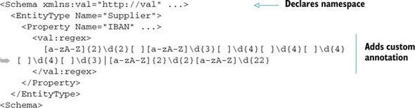
Naturally, you can add attributes following the same principle. There’s no technical limitation—the choice is up to you.
Keep in mind that not all tags in the EDM accept inner custom tags. The following tags don’t allow customizations:
- Using
- Schema
- Key
- PropertyRef
The reason for this limitation is that those tags don’t have a correspondence in the Entity Framework metadata object model, so they can’t be accessed. Similarly, MSL tags can’t be customized, whereas SSDL and CSDL tags can.
Note
That last sentence probably sounded like Jabba the Hutt speaking without subtitles, but don’t worry; in chapter 12, which focuses on metadata, you’ll learn about the metadata object model and tag customization.
For the moment, keep in mind that you can customize the EDM. The real power that comes from using this technique will be revealed later.
5.6. Summary
In this chapter, you’ve learned what you need to know to create and map entities to tables. We have not covered some very task-specific details, like the mapping of stored procedures, because they’ll be discussed in depth in chapter 9.
Mapping is a complicated task at first, but when you understand the use of the five main elements of the mapping (EntitySet, EntityType, AssociationSet, Association, and EntitySetMapping), there’s little more to learn. They, in combination, open the door to every mapping scenario.
Fortunately, creating the CLR classes is simpler than creating the EDM. Thanks to the POCO support, you can have classes that are completely ignorant of Entity Framework or any other persistence mechanism, allowing you to focus only on the business problem.
It was a long trip from defining classes to mapping them through to the database. If you have a complex model, you can end up spending a lot of time maintaining this infrastructure code. This is what drove the Entity Framework team to create a designer. By using the designer, you only need to worry about the business code, leaving to the designer the burden of creating the plumbing.
Now that you know how to map the domain model and how to use the power of querying with Entity Framework, it’s time to learn how to modify objects and persist their modifications into the database. This will allow you to start developing real projects.