
Chapter 14. Designing the application around Entity Framework
- Basic concepts of layered architectures
- Principles of domain-driven design
- Repository pattern implementation with Entity Framework
This chapter moves slightly away from what you may expect from a book about ADO.NET Entity Framework. We’ve faced the matter of persistence from a technical point of view, trying to understand how to use this O/RM tool to store a graph of objects in a relational database. In this chapter, we’re going to discuss the same topic but from an architectural point of view.
First, we’ll look at how to integrate Entity Framework in a typical three-layer architecture, which represents a good and widely used strategy for designing modern applications. But layering itself may not be helpful in handling the complex business logic typical of enterprise applications; in these cases, your design must move toward a more suitable domain-driven design modeling style. Finally, we’ll look at how you can shape your object model to handle this kind of architecture and how Entity Framework fits in.
14.1. The application design process
As software architects, we tend to work on two kinds of applications: those that will never see a second release, because they’re built for a specific need of the moment; and meaningful products that are destined to last through time, perhaps evolving as the years go by. In the latter case, despite the complexity of the problems to be handled, we don’t need something that just works. We must try to achieve a result that meets the following requirements:
- Robust—This guarantees that the code does its job in every situation.
- Maintainable—This makes future bug fixes as easy as possible.
- Expandable—This means you can implement new functionality or improvements with little effort, and without greatly affecting the overall architecture.
Meeting these requirements isn’t easy. A common technique to improve your chances is to split the application into simpler parts, called layers, with each one having its own specific functional responsibilities.
Three-layer applications, whose conceptual schema is shown in figure 14.1, are the most common example of such a layered architecture.
Figure 14.1. A diagram of the three-layer architecture
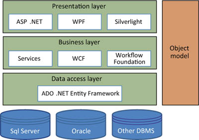
Starting from the bottom, a three-layer application consists of these layers:
- Data access layer—Interacts with the database and shields the rest of the application from its specific logic. Concepts like connections, commands, and tables only make sense within this layer and should never be exposed to the upper layers. This is also where Entity Framework fits in; in most cases, it can be considered the entire data access layer on its own.
- Business layer—Holds all the business logic and provides services that implement the real-world processes that the application is built to take care of. Although it doesn’t care where its inputs come from, it knows whether a fund transfer can take place between two bank accounts and how to handle it correctly, invoking the data access layer when it needs to query the database or store something there.
- Presentation layer—Contains all the logic for interacting with the user, correctly rendering windows or web pages, and interpreting user commands, translating them to business method invokes.
Each layer can interact only with the one immediately lower, sending and receiving messages in the form of classes that belong to the application’s object model, which is a sort of common language shared among them all.
Although it’s designed to bring simplicity to our software, this layered architecture requires more effort on the part of the developer compared to applications that have a monolithic structure. Layered applications have more class libraries, references, classes, and so on—in other words, more code! But the layered architecture offers the tremendous advantage of splitting this complexity across simpler elements that are easier to implement, test, and maintain, with obvious benefits on the overall result.
14.2. A typical three-layer architecture
To better understand how concerns should be separated into the three layers, let’s consider a practical example. Let’s go back to the OrderIT application to reconsider some of its requirements and rethink its architecture. We’ll implement the feature that allows customers to place orders. Imagine you’re building an ASP.NET web application with a Place a New Order page like the one shown in figure 14.2.
Figure 14.2. An interface for an order-placing web page
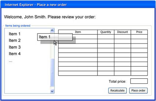
This page features some nice rich client interaction, like allowing drag and drop from the list box on the left to the grid on the right to compose an order, and it has a couple of buttons to calculate the total amount and to eventually place the order.
14.2.1. Filling the product list
The first task the web page has to accomplish, once loaded, is filling the list on the left with all the products currently available, as in the following listing.
Listing 14.1. Filling the productsList list box
C#
protected void Page_Load(object sender, EventArgs e)
{
  if (!IsPostBack)
  {
    var availableProducts = ProductsService.GetAvailableProducts();
    this.productsList.DataSource = availableProducts;
    this.productsList.DataBind();
  }
}
Protected Sub Page_Load(ByVal sender As Object, ByVal e As EventArgs)
  If Not IsPostBack Then
    Dim availableProducts = ProductsService.GetAvailableProducts()
    Me.productsList.DataSource = availableProducts
    Me.productsList.DataBind()
  End If
End Sub
In this listing, a lot of presentation logic, like triggering the Load event or the ListBox data binding, is provided under the hood by the ASP.NET Framework. But you should notice that page code has absolutely no knowledge of where the list of available products comes from, nor does it know when a product is available according to the business logic.
A static ProductsService class holds the code that retrieves the available products; its code can be seen in the next listing.
Listing 14.2. Retrieving available products
C#
public static class ProductsService
{
  public static List<Product> GetAvailableProducts()
  {
    using (OrderITEntities ctx = new OrderITEntities())
    {
      return ctx.Products
               .Where(p => p.QuantityInStock > 0)
               .ToList();
    }
  }
}
VB
Public Module ProductsService
  Public Function GetAvailableProducts() As List(Of Product)
    Using ctx As New OrderITEntities()
      Return ctx.Products.Where(Function(p) p.QuantityInStock > 0) _
                .ToList()
      End Using
  End Function
End Module
The ProductsService class is part of the business layer, and it has a single responsibility: it models the business rule that makes a product available. That rule could be something like, “we still have stock for that item,” or “this item can be sold in the current period of the year.” Its logic is implemented within the GetAvailableProducts method, which knows how to query the data access layer to retrieve a list based on the rule. In any case, ProductsService can’t see what its caller is going to do with that list of products, nor does it know how the context is actually retrieving them.
As we said in the previous section, Entity Framework can be considered the application’s data access layer, because it shields the business layer from concepts like connecting to a relational database and executing a query. To establish communication among the layers, you need them to share a common vocabulary in terms of an object model (for the Product class in the previous example) and to use it to exchange information with each other.
This example showed a case where a requirement can be fulfilled with the cooperation of all the three application layers. Despite this being the most common situation, there are also cases in which functionalities don’t traverse a layer boundary: the form’s drag-and-drop logic, for example, belongs entirely to the presentation layer and is totally unknown to the layers below.
14.2.2. Calculating order totals and saving them to the database
The user can recalculate the order total by clicking the Recalculate button. When the button is clicked, the application has to evaluate whether discount lines have to be created, according to the business requirements:
If the customer buys more than five items of the same product, there is a discount of 10 percent for each subsequent item. Should the discount be applicable, the order must contain two details: the first contains data about the first five items with no discount, and the other contains data about the additional items and the related discount.
When the user clicks the Recalculate button, the web page executes code similar to the following.
Listing 14.3. Calculating the order total
C#
private void btnCalculateTotal_Click(object sender, EventArgs e)
{
    Order order = getCurrentOrder();
    OrdersService.PreProcess(order);
    this.bindOrderData(order);
}
VB
Private Sub btnCalculateTotal_Click(ByVal sender As Object,
  ByVal e As EventArgs)
    Dim order As Order = getCurrentOrder()
    OrdersService.PreProcess(order)
    Me.bindOrderData(order)
End Sub
Even though you’re triggering this logic from the presentation layer, the rule belongs to the business layer. Thus it would be incorrect to pollute the click event handler with code that explores the order details and decides whether it should benefit from a discount; it makes much more sense to encapsulate that logic within a specific class, called OrdersService, which has the responsibility and the knowledge to rearrange order details according to the discount logic.
We won’t dive into the actual implementation of the PreProcess method, but you should appreciate how a layered architecture offers an undeniable advantage in terms of code simplicity, logic, and reusability (which often leads to easier maintainability). The code that implements the discount logic is always the same, regardless of the client. If you were to change from using a web page to a WPF application, you could easily reuse it. At the same time, any bug fixes or changes to the business rules have no impact on the user interface code and remain confined in the OrderService class.
When it comes time to save an order, things tend to become tricky, because you have to pursue several steps:
1. Verify whether user inputs are correct.
2. Verify whether there’s enough stock of the item being ordered.
3. Update the item stock.
4. Save the order and its details to the database.
5. Notify the user that the order was correctly placed, perhaps sending an email.
While dealing with such a workflow, the presentation, business, and data access layers interact according to logic that can become rather complex. In such cases, a UML sequence diagram like the one in figure 14.3 can help to represent all the interactions.
Figure 14.3. A sequence UML diagram of the order-placing process
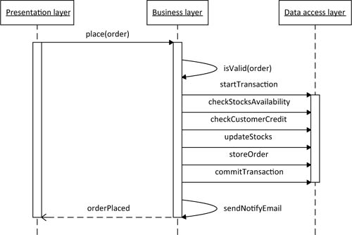
This diagram illustrates how messages flow across the various application layers, and shows the actors involved with the exchange and their lifecycle.
14.2.3. Dealing with higher levels of complexity
Earlier in this chapter, we mentioned the concept of an application’s object model, which represents a common library that all the application layers can use to communicate with each other and to store information. The Order class is part of OrderIT’s object model, so it holds all the order data, such as the details, the customer that placed the order, and the order time.
There aren’t any rules carved in stone about how an object model has to be made. For example, nothing prevents you from building it upon the well-established Data-Set/DataTable infrastructure we’ve been using since .NET Framework 1.0. But when dealing with a layered architecture, it’s common to see object models made of various classes, whose shapes come directly from the tables of the underlying data source. Each instance maps to a specific row of the database and stores the row’s primary key value to keep track of this relationship. Often, those classes are somehow interconnected, sometimes by holding a reference to another object, or sometimes only by storing its key.
Unfortunately, as complexity arises, this kind of architecture begins to show its limits. There’s nothing wrong with layering itself, but the model we just presented has two main issues that need to be addressed:
- All the logic resides outside the object model and tends to concentrate within a series of business methods, giving the application a potentially dangerous procedural flavor.
- There’s no guidance on how the object model itself should be built, which is the main reason for it to mime the database schema, regardless of whether you implement it using plain classes or DataTables. Although the data is ultimately stored in a relational database, you still have a full object-oriented programming language at your disposal, and this model leaves a lot of its peculiarities unused; there may be a way to use them to achieve a better design.
In conclusion, we need a different starting point: something that isn’t strictly related to how data is shaped in our database, but that helps us model the real-world domain the application is supposed to manage. The result of this process is called the domain model, and it’s the central concept behind domain-driven design.
14.3. Principles of domain-driven design
The first thing we should point out when talking about domain-driven design (DDD) is that it isn’t a brand-new kind of architecture, different from layering. It’s a bunch of rules and formalizations to effectively design the application’s business layer or, better said, the domain model.
As we’ve discussed, every class in a layered architecture has a specific functionality, and that means easier coding and improved maintainability. But everything is designed by keeping in mind the precise role that the object will have in the application ecosystem.
In contrast, with DDD you start from a different and innovative point of view: the aim of the designer is to let the domain model be the object-oriented alter ego of the real-world concepts the application is supposed to handle, keeping track of their attributes and relationships and implementing the same behaviors. It interacts with three other application layers, defining an architectural partitioning much like what you’re used to, as shown in figure 14.4.
Figure 14.4. Application layering according to DDD
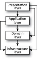
Once again, starting from the bottom, the first layer is the infrastructure layer, which carries a slightly broader responsibility than its data access layer counterpart. The infrastructure layer encompasses all the technical functionality that the upper layers may need, such as sending email, interacting with a database, or opening TCP/IP channels.
When layering according to DDD, the infrastructure layer doesn’t just manage data access, although this feature represents a big part of it. You’ll see shortly that you can use Entity Framework’s designer in Visual Studio to build an Entity Data Model, which can be thought as a raw domain layer. Thanks to that, when it comes time to fetch or store data to the database, Entity Framework completely shields you from what’s needed under the hood to communicate with it: you won’t have to open connections or use commands to execute stored procedures anymore, because you won’t code over tables but over a fully object-oriented model.
That’s why, when dealing with a three-layer architecture, we pointed out that Entity Framework fits inside the data access layer or, in some cases, can be considered the entire data access layer on its own; this is still valid in DDD, when talking about the infrastructure layer. Should other services (emails, third-party web services, and so on) be needed, they’re implemented in other assemblies. These assemblies, along with the Entity Framework ones, together form the application’s infrastructure layer.
We already talked about the domain layer. The application layer coordinates the interactions between the various layers and objects of the application. Usually this layer is kept thin; it shouldn’t hold any business concepts, because those belong to the domain layer.
On the side, the presentation layer is much the same as before, taking care of anything that concerns displaying data and reacting to user input.
DDD introduces a few new concepts related to how a domain model should be created. Let’s explore them in the context of OrderIT.
14.3.1. Entities
Let’s start building the OrderIT domain model following the application requirements, as you did in chapter 2, looking particularly at the first feature you need to fulfill:
- OrderIT must store data about customers.
- Each customer has a name, billing address, and shipping address.
The customer is the first business concept that finds a place in the application, and you also have a small subset of data you need to track for it: name, billing address, and shipping address. Let’s imagine that you did such a great job that the application will be a commercial success in the near future, having hundreds of registered customers. Probably among them you’ll find many with the same names, such as John Smith (or Mario Rossi, if you lived in Italy); moreover, some of them could move over the years, so the users would need to update their addresses.
OrderIT will need to keep on correctly placing orders and dispatching items, no matter how many matching names are in the database and how many times they change locations. If OrderIT wasn’t able to do so, users would probably end up sending goods to the wrong people and wouldn’t receive payments for their bills.
In other words, some business concepts (like a customer) own a well-defined, sometimes implicit, identity that isn’t related to their attributes and that remains the same for their entire lifecycle within the application. Objects with such features are called entities.
Order, too, is an entity for this application: an order has its own lifecycle, and while it lasts, it should always be unambiguously identifiable; that’s why after it’s created, every order is given a unique and immutable number that represents its identity field. Every entity should have one, and that’s the first aspect deserving attention when a brand-new entity appears in your domain.
The entity concept is strictly related to the application’s purpose, and not to the real-world object that’s being modeled. If you were working on an inventory-management application that used the concept of incoming and outgoing orders to increase and decrease the stock of a given item, you probably wouldn’t care about an order’s life-cycle and identity: you’d just want to know whether it contains a certain item or not. In other words, two orders for the same amount of the same item would be identical for that business process. In this example, Order wouldn’t be an entity for your domain model. We’ll get back to this distinction shortly.
In OrderIT, Order and Customer have a relationship with each other that’s called an association. Figure 14.5 shows an early version of the domain model you’re building.
Figure 14.5. An Order and Customer UML diagram

Another concept that the domain-model philosophy has is the value object.
14.3.2. Value objects
Let’s go back for a moment to the requirement of storing customer data:
- OrderIT must store data about customers. Each customer has a name, billing address, and shipping address. The address isn’t plain text, but consists of four separate pieces of data: street, city, ZIP code, and country.
We can easily identify another business concept in that statement: the address. But the nature of this object is considerably different from Order or Customer. Does OrderIT really need an addresses catalog? Does an address have its own lifecycle? Are two addresses different even though they’re pointing to the exactly the same location? The answer is no. You only need a customer’s address to correctly deliver bills and goods, so two addresses with the same attributes can be considered absolutely the same address. That means there are objects whose equality is solely determined by their attributes. These objects are called value objects.
Typically value objects are small classes that group one or more attributes used in many points of the domain model, maybe encapsulating some sort of behavior. They’re not independent, which means a value object can’t exist on its own: in OrderIT, for example, an address has no business meaning unless it’s related to an order, to store its delivery address.
Relationships that involve value types are called compositions. Figure 14.6 shows how Address fits into the domain model to represent one customer’s billing and shipping addresses.
Figure 14.6. UML diagram with the Address value object
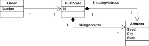
Considering their nature, value objects can be freely exchanged. Given two customers, the following statement can be used to copy the first customer’s billing address data to the other:
C#
customer2.BillingAddress = customer1.BillingAddress;
VB
customer2.BillingAddress = customer1.BillingAddress
You may argue that a statement like this isn’t completely free of side effects: we’re talking about .NET classes, and modifying customer1’s billing address would result in a harmful bug, because customer2 would inherit the change as well.
A possible solution for that (and absolutely a best practice) is always designing value objects as immutable, which means giving them read-only properties and fields. This rule has also has a more philosophical reason behind it: because a value object’s identity is completely defined by its attributes, modifying one of them should result in a brand-new object. That’s why it’s more correct to create a new instance when its values need to be changed.
14.3.3. Handling associations correctly: domain roots and aggregates
Each order must keep track of the products and quantities it involves. Hence, it’s pretty clear that you need to add a collection of OrderDetail objects.
Based on what we said in the previous pages, you may wonder whether OrderDetail should be considered an entity or a value object. Two order details that relate to the same item and have the same quantity could be considered exactly the same thing, so at first sight, you may consider OrderDetail a value object.
When it comes to dealing with domain-model persistence, though, you must be aware of how the domain design impacts the infrastructure layer. Saving a detail table of value objects isn’t easy, because they don’t have their own identity field that maps the instance to a specific and well-identified database row. That’s why it’s sometimes worth sacrificing the model’s pureness to achieve an easier implementation when writing the code.
This chapter’s concepts work whether OrderDetail is modeled as an entity or as a value object.
Order and OrderDetail provide a typical example of a master-detail relationship. To make the relationship navigable in both directions, you need an Order property in the OrderDetail class that references the order to which it belongs, and you need a collection of details (OrderDetails property) in the Order object.
Does it make sense to blindly apply this pattern to every association in the domain model? Earlier in this chapter, for example, you saw that Customer and Order have a similar association, but you designed it as navigable only from the Order. Should you add an Orders property to the Customer entity?
There’s a subtle difference between these two examples: an order detail is useless if taken away from its root; the Order entity along with all its details encompasses the business concept of a real-world order. Using a term specific to DDD, they form an aggregate of entities, whose root is the order itself. When you’re dealing with aggregates, you’re never supposed to directly reference an entity that isn’t the aggregate’s root: following this rule results in a more polished domain, in which external objects only refer to the order as a whole and never deal with its internal composition.
That said, implementing a master-detail relationship between the two makes a lot of sense, because you’re always going to access order details from the main Order entity. Figure 14.7 shows how to represent an aggregate in a UML diagram.
Figure 14.7. An updated UML diagram with Order and Customer aggregates

Notice that the Customer entity, along with its addresses, also forms an aggregate. Note also that you’re allowed to reference other entities from within an aggregate, as it happens between OrderDetail and Product.
The relationship between a customer and its orders now appears clearly different from the relationship between an order and its details, because they aren’t part of the same aggregate! In fact, there’s nothing wrong with directly referencing an order without coming from the customer that placed it. An order makes a lot of sense (and has a huge business meaning) even if you don’t consider which customer it belongs to. In DDD terms, a customer and its orders aren’t an aggregate.
Why should you a avoid master-detail relationship between customers and orders? Because associations are easy to navigate, but they don’t come for free: they have a significant cost in terms of complexity and performance. Moreover, getting all the orders for a given customer doesn’t have a great business meaning; more often, you’ll need to recover orders placed within a certain period of time, or orders that are still waiting to be delivered. Repositories are better candidates for accomplishing these tasks, because they provide full object-oriented querying features. We’ll cover repositories later in this chapter; now we need to work a bit more on the order entity.
14.3.4. Refining the model
Now that the Order and Customer parts of your domain model are well defined, it’s time to think about how the discount calculation fits in:
The policy for discounts states that if the customer buys more than five of the same product, there is a discount of 10 percent for each subsequent item. Should the discount be applicable, the order must contain two details: the first contains data about the first five items with no discount, and the other contains data about the additional items and the related discount.
You implemented this feature earlier as a method in the OrderService class. Now you’re starting from a different perspective, because you’re trying to model an object-oriented representation of the order business concept. In this context, it’s natural to include a ComputeDiscount method in the Order class. This method should explore the details collection and eventually add discount rows where needed.
Listing 14.4 shows a sample implementation of this method. Notice that it often refers to this when the Order entity is involved, because it’s an instance method.
Listing 14.4. Computing an order’s discount
public void ComputeDiscount()
{
  compactOrderDetails();
  var detailsToDiscount =
    this.Details.FindAll(d => d.Quantity > 5);

  foreach(var orderDetail in detailsToDiscount)
  {
    int exceedingQuantity = orderDetail.Quantity - 5;
    orderDetail.Quantity = 5;
    OrderDetail discountDetail = new OrderDetail
    {
      Order = this,
      Item = orderDetail.Item,
      Quantity = exceedingQuantity,
      Discount = 0.1
    }
    this.Details.Add(discountDetail);
  }
}
VB
Public Sub ComputeDiscount()
    compactOrderDetails()
    Dim detailsToDiscount = Me.Details.FindAll( _
      Function(d) d.Quantity > 5)

    For Each orderDetail In detailsToDiscount
        Dim exceedingQuantity As Integer = orderDetail.Quantity - 5
        orderDetail.Quantity = 5
        Dim discountDetail As New OrderDetail() With _
        { _
          .Order = me, _
          .Item = orderDetail.Item, _
          .Quantity = exceedingQuantity, _
          .Discount = 0.1 _
        }

        Me.Details.Add(discountDetail)
    Next
End Sub
A domain model is called anemic when it only contains data, and no code. Many people think that a domain should be modeled that way, because usually processes change, but data doesn’t, and modifying a domain class after the application has shipped could require great effort, given its centrality in the overall architecture. But remember that your ultimate goal is to take a real-world order and describe it as a class. As a general rule, there’s nothing bad about adding logic to a domain class if you’re sure it belongs to the class. In any case, you’ll shortly see that there are better options in this case, and the model can be further improved.
Now let’s imagine that, after some months of OrderIT running in production, this promotion discount expires, perhaps to be replaced with another one with different logic. This would force you to roll up your sleeves and modify the domain code; but besides that, isn’t there something conceptually wrong with a changing promotion requiring maintenance on the order class? Should an order discount really belong to the order itself?
When you added the discount logic to the order, you hid a concept that you must make explicit to improve the overall design: the logic that determines whether an order is suitable for a discount or not. This logic is a new element of the OrderIT domain model, which we’ll call Discount-Policy. Figure 14.8 shows the updated UML diagram.
Figure 14.8. The refined model of the discount policy
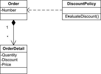
The CalculateDiscount method can now be refactored, as shown in the following listing.
Listing 14.5. Computing an order’s discount with DiscountPolicy
C#
public void ComputeDiscount()
{
  compactOrderDetails();
  this.DiscountPolicy.EvaluateDiscount(this);
}
VB
Public Sub ComputeDiscount()
  compactOrderDetails()
  Me.DiscountPolicy.EvaluateDiscount(Me)
End Sub
Notice how the DiscountPolicy class encapsulates the whole discount calculation logic.
The step you just made brings great benefits to our design. The domain model is formally more correct, because you introduced a new business concept that avoids polluting the Order entity with responsibilities that don’t belong to it. Moreover, it gives you the chance to use the object-oriented paradigm, using the Strategy pattern to easily support new discount policies to come.
This design isn’t applicable to every situation. Sometimes the business process is too complex and involves too many objects, and you don’t want to include all that logic in a single entity; sometimes there isn’t a specific entity to which the processes belong. In such cases, you can introduce specific objects in your domain, called domain services, to handle those tasks. In OrderIT, you can use a domain service to implement the order-placing logic, which involves saving the new order, updating the stock, notifying the customer by email, and so on.
But beware of abusing domain services, or you’ll soon be dealing again with procedural code. A process must be implemented as a service only when it meets all of these criteria:
- The service represents flows that don’t directly belong to an entity or a value object, but that interact with various domain model elements.
- The service interface is solely composed of domain model objects.
- The service logic is stateless, which means an invocation result doesn’t depend on previous results.
So far, we’ve focused on how the domain model must be shaped, without caring whether its building blocks are already in memory or need to be fetched from a database or created as new. In the next section, you’ll discover which tools you can use to retrieve references to entities and value objects so you can use and manipulate them in the code.
14.4. Retrieving references to a domain’s entities
If domain objects spend their whole lifecycle in memory, they should always be reachable from your code; otherwise, the garbage collector will wipe them out. Thanks to the persistence layer, objects are also stored in other ways, such as in databases, so they can be kept alive even if the application quits, the server restarts, or the code doesn’t keep references to them. Sooner or later, you’ll want to recover that reference. You could do it by navigating object references within an object graph, but you’d still need an aggregate root to start from. This is where repositories fit in.
14.4.1. Repositories at a glance
In DDD, you model the application’s business concepts in the form of classes, and the most intuitive way for the object-oriented programmer to group a set of instances of the same class is using collections. In fact, if you put aside for a moment the need to store entities in a relational database, it would probably be most convenient to hold all the customer references in a globally reachable AllCustomers collection somewhere in the application design. For OrderIT, a customer would exist only if it was in that collection, and removing a customer from the collection would mean deleting it.
Unfortunately, in the real world, durable data needs to be stored in a durable platform, but it would still be great to abstract the storage as if it were made of collections. That would offer the best of both worlds. A repository is an object that acts like a collection of aggregate roots, giving the client the illusion that every entity it contains is already in memory. Entities can be added or removed from a repository to carry out inserts and deletes, and a repository can be queried to get references to the entities it holds.
Let’s try to find a way to implement a generic repository that uses Entity Framework to interact with the relational database.
14.4.2. Implementing a repository
Implementing a repository is an almost trivial task, because Entity Framework already uses a repository-like pattern internally: each entity belongs to a well-defined entity set, and you only need to wrap them.
If Entity Framework already provides entity sets, why would you need to build your own repositories? To answer this question, we must go back for a moment to the application layering we introduced in section 14.3. If you look at figure 14.4, you can see that repository implementations belong to the infrastructure layer, because they can interact with the underlying database to fetch customer data and rebuild a customer entity. This requires a reference from the infrastructure layer to the domain layer.
This works perfectly when the interactions between the domain and infrastructure layers are orchestrated by the application layer: for example, when a web page must query the database to get a customer list. But it’s not uncommon for domain entities to require the repository’s services too. For example, a DiscountPolicy may need to check a customer’s order history to determine whether a discount should be applied.
For this reason, you must separate repository implementations from their interfaces (thus building your own repository library). The repository implementations belong to the infrastructure layer, and the interfaces are part of the domain layer. A domain class would only reference the interface, but an Inversion of Control (IoC) container would then inject the actual implementation.
Another important reason to build your own repositories is for testing purposes. We’ll explore this topic later in the book.
Because repositories must act as if they were in-memory collections, it’s logical to inherit the generic interface from ICollection<T>, which provides Add, Remove, and other typical collection methods and properties. You can then add some specific functionalities. You’ll start by defining the repository interface as shown in this listing.
Listing 14.6. A generic IRepository<T> interface
C#
public interface IRepository<T> : ICollection<T> where T : class
{
  IEnumerable<T> Query(Func<T, bool> predicate);
  T GetSingle(Func<T, bool> predicate);
  void Update(T entity);
}
VB
Public Interface IRepository(Of T As Class)
  Inherits ICollection(Of T)
  Function Query(ByVal predicate As Func(Of T, Boolean)) As _
              IEnumerable(Of T)
  Function GetSingle(ByVal predicate As Func(Of T, Boolean)) As T
  Sub Update(ByVal entity As T)
End Interface
The IRepository<T> interface adds three methods. Query and GetSingle can be used to query the repository’s content and retrieve an enumerable or a single entity, respectively. Both methods accept a predicate as an argument (that’s a delegate that accept an instance of a T and returns true or false) and can be easily invoked using a lambda expression, as you’re used to doing with LINQ’s Where extension method. Last but not least, you can use Update to attach an existing entity to the repository.
The concrete Repository<T> class has some prerequisites to work properly: first, it must be instantiated within a persistence context, which means it must operate on a valid and alive Entity Framework context. This is why, in order to initialize a repository, you need a context whose reference will be held for further use.
This isn’t enough, though, because you can’t query or add entities directly to the context. You also need a reference to the entity’s entity set. The following listing shows the Repository<T> constructor.
Listing 14.7. Repository constructor
C#
public class Repository<T> : IRepository<T> where T : class
{
  private ObjectContext context;
  private ObjectSet<T> entitySet;

  public Repository(ObjectContext context)
  {
    if (context == null)
      throw new ArgumentNullException("context");

    this.context = context;
    this.entitySet = context.CreateObjectSet<T>();
  }
}
VB
Public Class Repository(Of T As Class)
  Implements IRepository(Of T)
  Private context As ObjectContext
  Private entitySet As ObjectSet(Of T)

  Public Sub New(ByVal context As ObjectContext)
    If context Is Nothing Then
      Throw New ArgumentNullException("context")
    End If

  Me.context = context
    Me.entitySet = context.CreateObjectSet(Of T)()
  End Sub
End Class
Now you can get back to the interface and look at the Query method. As you can see in listing 14.8, when you have a reference to the object set, its implementation is straightforward. All you need to do is query the object set, forwarding the predicate to LINQ’s Where extension method. GetSingle uses the same code, but it returns a single instance of the T entity.
Listing 14.8. Query and GetSingle implementations
C#
public IEnumerable<T> Query(Func<T, bool> predicate)
{
  return this.entitySet.Where(predicate);
}

public T GetSingle(Func<T, bool> predicate)
{
  return this.Query(predicate).Single();
}
VB
Public Function Query(ByVal predicate As Func(Of T, Boolean)) As _
                IEnumerable(Of T)
    Return Me.entitySet.Where(predicate)
End Function

Public Function GetSingle(ByVal predicate As Func(Of T, Boolean)) As T
    Return Me.Query(predicate).[Single]()
End Function
IRepository<T> provides two methods to connect an entity to the underlying ObjectSet<T>: Add comes from the base ICollection<T> interface you’re inheriting from, whereas the Update method was explicitly defined in listing 14.6. You have to implement them for the context to be able to track every change you make to the entity and generate proper persistence queries. A third method, Remove, also belongs to the base ICollection<T> interface, and it can be used to flag the given entity for deletion. The following listing shows what we just described.
Listing 14.9. Add, Remove, and Update implementations
C#
public void Add(T entity)
{
  if (!this.Contains(entity))
    this.entitySet.AddObject(entity);
}

public void Update(T entity)
{
  if (!this.Contains(entity))
    this.entitySet.Attach(entity);
}

public bool Remove(T entity)
{
  if (!this.Contains(entity))
    return false;
  this.entitySet.DeleteObject(entity);

  return true;
}
Public Sub Add(ByVal entity As T)
  If Not Me.Contains(entity) Then
    Me.entitySet.AddObject(entity)
  End If
End Sub

Public Sub Update(ByVal entity As T)
  If Not Me.Contains(entity) Then
    Me.entitySet.Attach(entity)
  End If
End Sub

Public Function Remove(ByVal entity As T) As Boolean
  If Not Me.Contains(entity) Then
    Return False
  End If

  Me.entitySet.DeleteObject(entity)

  Return True
End Function
All these methods internally use Contains (which you can see in listing 14.10) to determine whether the entity already belongs to the object context. Contains, in turns, asks the state manager for the entity’s state and evaluates it.
Listing 14.10. ICollection<T>.Contains implementation
C#
public bool Contains(T item)
{
  ObjectStateEntry state;

  if (!this.context.ObjectStateManager
           .TryGetObjectStateEntry(item, out state))
     return false;

  return (state.State != EntityState.Detached);
}
VB
Public Function Contains(ByVal item As T) As Boolean
    Dim state As ObjectStateEntry

    If Not Me.context.ObjectStateManager.TryGetObjectStateEntry _
              (item, state) Then
        Return False
    End If

    Return (state.State <> EntityState.Detached)
End Function
In order to successfully implement ICollection<T>, the compiler requires you to also write members like Clear or GetEnumerator that aren’t useful in this scenario. We won’t cover their implementation here.
Let’s move on to the client’s point of view, and imagine how you would typically use a repository in your code. For example, if a discount should be applied to a customer’s first order, the discount rule could be defined as follows.
Listing 14.11. Typical repository usage
C#
public bool ApplyDiscount(Customer customer)
{
  IRepository<Order> orderRepository =
    container.Get<IRepository<Order>>();

  return orderRepository.Query(o => o.Customer == customer).Count() == 0;
}
VB
Public Function ApplyDiscount(ByVal customer As Customer) As Boolean

  Dim orderRepository As IRepository(Of Order) = _
    container.[Get](Of IRepository(Of Order))()

  Return orderRepository.Query(Function(o) o.Customer = customer) _
    .Count() = 0
End Function
Notice how the FirstOrderDiscountRule doesn’t directly reference the concrete repository class but uses it via its interface. You can achieve this by using an Inversion of Control container to keep the interface separated from the actual implementation; this is the meaning of the container variable the code refers to.
Inversion of Control is a well-known and widely used pattern for loosely coupling various application dependencies; if you’re interested in this topic, an internet search will turn up hundreds of related articles and libraries.
14.4.3. Getting a reference to a brand new entity
When you’re dealing with complex domains, building new entities can be challenging and require interactions between various aggregates in your domain model. Consider the Order entity and its relationship with DiscountPolicy, as discussed in section 14.3.4: what has the responsibility to associate an order to the proper discount policy? It can’t be the order itself, which hasn’t any knowledge of the various policies the application supports; at the same time, you don’t want the developer, who will use the domain model, to have the deep knowledge required to select the correct discount policy—that would reveal too many details of the Order class’s internal structure. In such cases, factories are what you need: they’re domain objects that are responsible for creating instances of aggregates.
Factories can also be useful when you need to invoke infrastructure services (like a logging service) and you don’t want to expose this logic to the end user.
Although in your entity data model you have navigation properties to traverse relations, Entity Framework 4.0 introduces the concept of foreign-key properties, which are plain scalar properties containing the associated entity’s ID. You can set them to modify this association if you want to. When you fetch an entity from the database, the foreign-key properties and their corresponding navigation properties are bound together, and changing the former results in an automatic update of the latter. To achieve the same behavior with new entities, you can use the ObjectContext.CreateObject<T> method.
In DDD, you shouldn’t use foreign keys, because they’re a technical and infrastructural concept that you shouldn’t pollute your domain model with. For the same reason, you shouldn’t explicitly invoke ObjectContext.CreateObject<T> within the domain model. But it’s also true that foreign-key features can be very useful in your infrastructure layer.
To keep the best of both worlds, you can use a factory to encapsulate this logic and use it when the time comes to create new entities.
14.5. Summary
In this chapter, we explored the basics of an application’s structure. We introduced a layered architecture, showing how the overall application design can benefit from better code organization and separation of concerns.
Then we moved on to domain-driven design (DDD), which aims to encapsulate the pure business logic in an object-oriented model, referred to as the application’s domain. We introduced some key building blocks, like entities, value objects, repositories, and factories, giving examples of how you could use them to rethink the OrderIT application you’ve been working on in this book. If you want to explore all these concepts more deeply, we recommend reading Domain-Driven Design, by Eric Evans (Addison-Wesley, 2003), which is considered the “bible” of DDD. Although these DDD concepts are abstract and don’t necessarily require a persistence framework such as Entity Framework, we showed how you can integrate Entity Framework with DDD.
Application architecture is a great place to start to achieve robustness and maintainability, but it covers only half of the journey. In the next chapters, you’ll apply these concepts to some typical real-world applications, and then we’ll focus on another technique that dramatically improves software quality: automatic code testing.