
Appendix C
Estimating Emissions from Storage Tanks
Emission rate correlations have been developed by industry and government agencies for storage tanks and secondary emission sources (U.S. EPA 1985, U.S. EPA 1998). Storage tanks are units common to almost every chemical process. They provide a buffer for raw materials availability in continuous processes and allow for storage of finished product before delivery is taken. Tanks have the potential to be major contributors to airborne emissions of volatile organic compounds from chemical facilities because of the dynamic operation of these units. There are two major losses mechanisms from tanks; working losses and standing losses. Working losses originate from the raising and lowering of the liquid level in the tank as a result of raw material utilization and production of product. The gas space above the liquid must expand and contract in response to these level changes. During tank emptying, air from the outside or an inert gas, if provided, enter the tank. Volatile organic vapors from the liquid evaporate in an attempt to achieve an equilibrium condition between the concentrations of each component in the liquid and gas phases. When the tank is filled again, these vapors in the gas exit the unit via the vent to be dispersed into the atmosphere unless pollution control devices are installed. Even if the tank level is static, standing losses from the tank occur as a result of daily temperature and ambient pressure fluctuations which cause a pressure difference between the gas inside the tank and the air outside.
There are four major types of storage tanks; fixed-roof, floating-roof, variable-vapor-space, and pressurized tanks. Equations for estimating emissions from fixed-roof and floating-roof storage tanks will be provided. The total loss (LT) is the sum of the standing (LS) and the working (LW) losses, as shown in the following equations. The standing losses are proportional to the vapor density, the tank vapor space volume, the vapor expansion factor, and an empirical parameter related to the degree of saturation of the gas with the volatile organic chemical. The working losses are proportional to the molecular weight of the liquid, the vapor pressure of the liquid, the throughput of liquid into and out of the tank, and two empirical factors related to the degree of saturation in the gas phase. Tables C-1 and C-2 contain the set of equations needed to calculate storage tank emissions for fixed- and floating-roof tanks, respectively. Equations are defined and numbered sequentially, with references to additional equations for the parameters appearing in each. Also, there are references to tables of data needed to carry out the calculations. Parameters in each equation are defined in subsequent equations in Tables C-1 and C-2 or in the tables referenced. These equations are described in detail in the EPA’s emission inventory database, and software is available that performs the emission estimates (the TANKS program) (http://www.epa.gov/ttn/chief/, under software labeled tanks).
Table C-1 Total Losses from Fixed-Roof Storage Tanks.

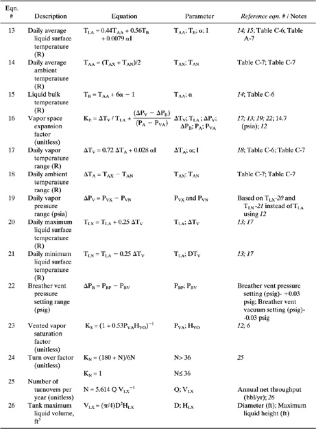
Table C-2 Total Losses from External Floating Roof Tanks.

Table C-3 Properties (MV, PVA, WL) of Selected Petroleum Liquids.
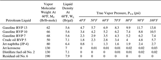
Table C-4 Properties (MV, PVA, WL) of Selected Petrochemicals.

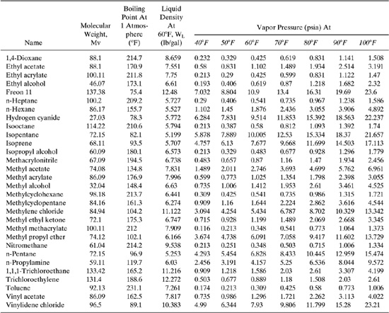
Table C-5 Vapor Pressure Equation Constants* for Organic Liquids.

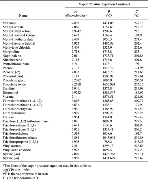
Table C-6 Paint Solar Absorbance for Fixed Roof Tanks.
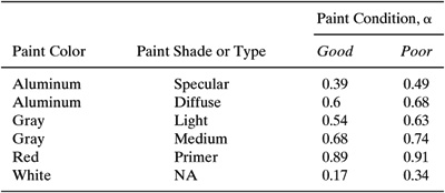
Table C-7 Meteorological Data (TAX, TAN, I) for Selected U.S. Locations.

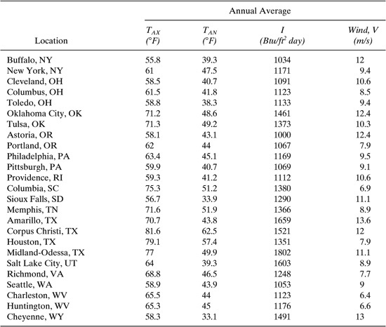
Table C-8 Rim-Seal Loss Factors, KRa, KRb, and n, for Floating Roof Tanks.
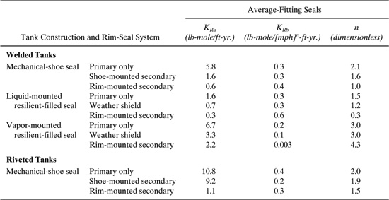
Table C-9 Average Clingage Factors, C.

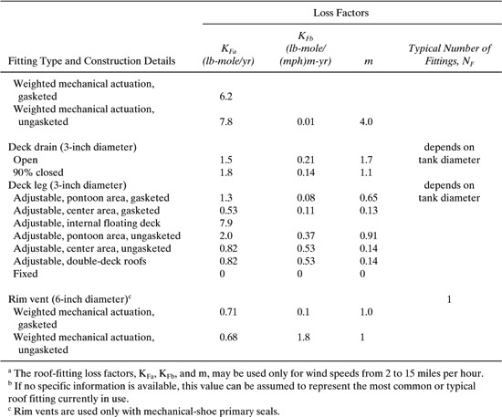
Table C-10 Deck-Fitting Loss Factors, KFa, KFb, and m, and Typical Number of Fittings, NF.

Example C-1 Emission Rate from a Fixed-Roof Storage Tank
Determine the annual emission rate of a mixture containing 50/50 wt. % of toluene and ethyl acetate from a vertical coned-roof tank in Chicago, Illinois. The tank is 10.8 ft in diameter, 9.8 ft high, it holds about 80 % of the total volume, and is painted white (good condition). The tank working volume is 5,425 gallons. The number of turnovers per year for the tank is 183 (i. e., the throughput of the tank is 99,278 gal/yr).
Solution:
1. Determine tank type. The tank is a fixed-cone roof, vertical tank.
2. Determine estimating methodology. The product is made up of 2 organic liquids, both of which are well mixed and miscible in each other.
3. Select equations to be used. For a vertical, fixed roof storage tank, the following equations apply:
LT | = LS + LW (1) |
LS | = 365 WVVVKEKS (2) |
LW | = 0.0010 MVPVAQKNKP (3) |
4. Calculate each component of the standing loss and the working loss functions.
a. Tank vapor space volume, VV.
Use Equation 4 from Table C-2. We need to know the vapor space outage, HVO. This can be determined using Equations 6 and 8 from Table C-1. The tank shell height (HS) is given as 9.8 ft, the stock liquid height (HL) is stated as 80% of HS, and the tank roof slope is assumed to be the value shown in notes to Equation 8 of Table C-2. Using these equations, we find
Vv=p⁄4(10.8)2(2.113)=193.65 ft3
b. Vapor density, WV.
Vapor density is calculated using Equation 11 of Table C-1. We first need to calculate the average liquid surface temperature (TLA) using Equations 13, 14, and 15. Using these equations, we find the value of TLA
TLA= (0.44)(508.9R) + 0.56(508.9R) + 0.0079(0.17)(1215)=510.5R
Next the value of PVA, the average vapor pressure at temperature TLA using Equation 12 of Table C-1. In order to calculate the mixture vapor pressure, the partial pressures need to be calculated for each component. The partial pressure is the product of the pure vapor pressures of each component (calculated above) and the mole fractions of each component in the liquid.
The mole fractions of each component are calculated as follows:
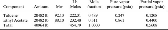
The vapor pressure of the mixture (PVA) is then 0.56 psia.
Third, calculate the molecular weight of the vapor, MV. Molecular weight of the vapor depends upon the mole fractions of the components in the vapor.
MV S Miyi
where
Mi= molecular weight of the component
yi= vapor mole fraction
The vapor mole fractions, yi, are equal to the partial pressure of the component divided by the total vapor pressure of the mixture. Therefore,
ytoluene = Ppartial/Ptotal = 0.1208/0.5608 = 0.2154
yethyl acetate = 0.4400/0.5608 = 0.7846
The mole fractions of the vapor components sum to 1.0.
The molecular weight of the vapor can be calculated as follows:

Since all variables have now been solved, the vapor density, WV, can be calculated:
WV=(88.968*0.5608)/(10.731*510.5)=0.00911 lb/ft3
c. Vapor space expansion factor, KE.
The vapor space expansion factor is calculated using Equation 16 of Table C-1. We must use equations 17, 18, 19, 20, and 21. The calculation of mixture vapor pressures in equation 19 is similar to the PVA calculation presented immediately above. The resulting vapor space expansion factor is
KE=19.5/510.5 + (0.168-0.06)/(14.7-0.56)=0.0458
d. Vented vapor space saturation factor, KS.
Using previously calculated parameters, Equation 23 provides the value for KS.
Ks=(1+0.53PVAHVO)-1
5. Calculate the standing storage losses
Ls=365 WvVvKEKs
Using the values calculated above:
Wv | = 0.00911 lb/ft3 |
Vv | = 193.65 ft3 |
KE | = 0.0458 |
Ks | = 0.941 |
Ls | = 365(0.00911)(193.65)(0.0458)(0.941) = 27.75 lb/yr |
6. Calculate working losses.
The amount of VOCs emitted as a result of filling and emptying operations can be calculated from Equation 3 using Equation 24 and using the stated turnover number for the tank, N.
LW = (0.0010)(88.97)(0.56)(2363)(1)(0.3306)= 38.92 lb/yr
7. Calculate total losses, LT.
Lt = Ls=Lw
where
LS | = 27.75 lb/yr |
LW | = 38.92 lb/yr |
LT | = 27.75 + 38.92 = 66.67 lb/yr |