
30 2. RELAXATION TYPE RESIDUAL STRESS MEASUREMENT METHODS
(a) (b)
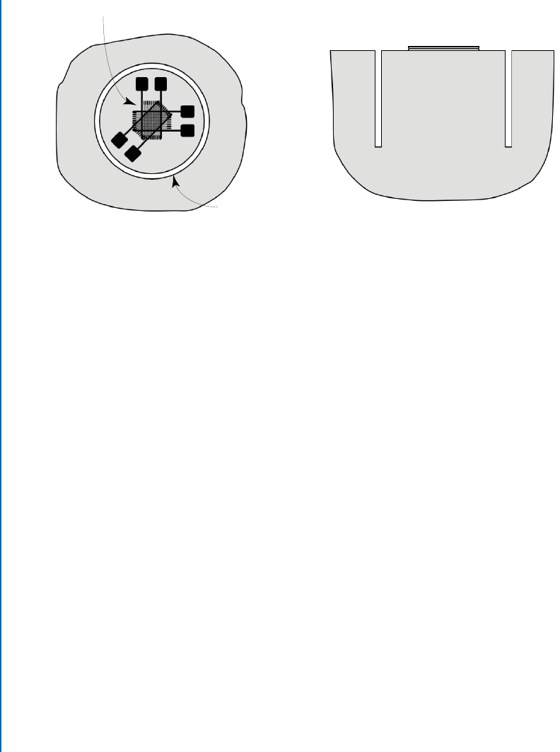
Strain Gauge Rosette
Ring Core
Figure 2.6: Ring-Core Method. (a) Plan view and (b) cross-section view.
e second way of using the Ring-Core Method is equivalent to a 2-D version of the
Slitting Method. In this case, sets of relieved strain readings are sequentially taken as the ring
depth is progressively increased in a series of small steps. ese strain readings provide the input
data for three integral equations similar to Equation (2.2), each specialized to a component of
the three in-plane residual stresses. e mathematical procedure is the same as for the Hole-
Drilling Method and is described in more detail in Chapter 5. In this way, the within-depth
profile of the in-plane stresses can be determined to a depth approximately equal to the ring
radius. Residual stresses at greater depths make rapidly decreasing contributions to the relieved
strains at the surface and cannot be resolved reliably.
Figure 2.6 illustrates the classical approach for doing Ring-Core residual stress measure-
ments using strain gauges. In recent years, full-field optical techniques have been introduced for
measuring the surface deformations. ese techniques enable measurements to be made over
a wide range of dimension scales, including microscopic. Of interest to note is that while the
strains that occur in Ring-Core measurements are greater than for the Hole-Drilling measure-
ments described below, the surface displacements that occur in both methods have similar sizes
for a given annulus/hole diameter. is occurs because the region within the annulus has large
strain but small radius, while the area outside the annulus/hole has smaller local strains but larger
radius. e two effects approximately balance each other, thereby giving similar displacements
in the two regions. Chapter 7 describes some commonly used optical measurement methods.
2.8 HOLE-DRILLING METHOD
e Hole-Drilling Method, illustrated in Figure 2.7, is similar in concept to the Ring-Core
Method, but with reversed geometry. While the Ring-Core Method involves making defor-

2.8. HOLE-DRILLING METHOD 31
mation measurements in the central area while the surrounding material is cut away, the Hole-
Drilling Method involves making deformation measurements in the surrounding area while the
central material is cut away. is similarity means that the two methods share many similar char-
acteristics and can use analogous calculation procedures to evaluate the residual stresses from the
measured deformation data.
In the classical Hole-Drilling Method, a specially designed strain gauge rosette is attached
to the specimen at the desired location. A hole is then incrementally drilled in a series of small
steps at the geometric center of the rosette, with strain readings taken after completion of each
depth step. Analysis of the relieved strain measurements enables the through-thickness profiles
of the three in-plane stress components. ese stress profiles can be determined to a depth ap-
proximately equal to the hole radius. ree sizes of strain gauge rosettes are commonly available
to accommodate holes of nominal diameter 1/8”, 1/16”, and 1/32” (3 mm, 1.5 mm, 0.75 mm).
Choice of rosette size used depends on the size of the specimen and the desired depth for the
stress profile evaluation.
(a) (b)
Strain Gauge Rosette
Hole
Figure 2.7: Hole-Drilling Method. (a) Cross-section view and (b) plan view.
e choice between the Hole-Drilling and Ring-Core methods mostly depends on pro-
cedural convenience and user preference. Of the two, the Hole-Drilling Method is by far the
more widely used, possibly also the most widely used among all residual stress measurement
methods. e reasons for this are the straightforward experimental procedure, the wide range
of applicable material types and specimen geometries, the relatively modest cost of the experi-
mental equipment and the reliability of the residual stress results. In addition, the drilled hole is
often sufficiently small compared with the specimen size that its presence does not significantly
impair specimen functionality. For this reason, the Hole-Drilling Method is sometimes called
“semi-destructive.” By comparison, the diameter of the annular groove used for the Ring-Core
..................Content has been hidden....................
You can't read the all page of ebook, please click here login for view all page.