

146 7. OPTICAL TECHNIQUES
Stress Axis
ILLUM
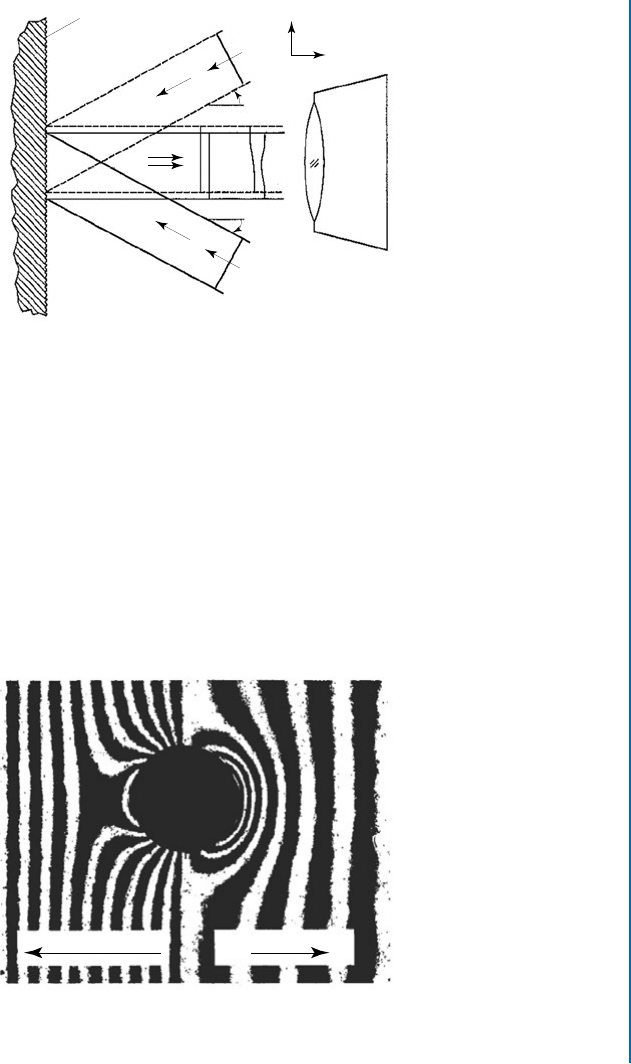
Figure 7.2: Example holographic fringe pattern (from Nelson et al. (1994)).
reference beam going directly to the recording medium (“holographic camera”), and the object
beam first illuminating the test object surface and then reflecting onto the recording medium.
e two beams mix there and form an interference pattern which is stored as a hologram by
developing the recording medium. After the initial interference pattern exposure, a drill on a
rotary base is used to cut a hole in the specimen and the recording medium is then re-exposed
to reference and object beam light. A pattern of dark and light interference fringes appears and
is viewed through a video camera.
A characteristic of the holographic method is that the fringe patterns are observed in
analog format as a sequence of light and dark lines. Amplitude information is available but not
sign, i.e., it is not known whether the fringes represent tension or compression. However, the
sign of the associated deformations can be determined by a subsequent measurement where
deformations of known sign are deliberately applied to the test object and then noting whether
the observed fringes move closer together or further apart. Alternatively, the same effect can be
achieved by slightly rotating the incident beam on the test object. is superposes an artificial
tensile or compressive field over the observed fringe pattern, depending on the beam rotation
direction. In the latter case, the superposed fringes are called “carrier fringes.”
7.3 MOIRÉ INTERFEROMETRY
Moiré interferometry is a variant interferometric technique that has been investigated for hole-
drilling residual stress measurements. Figure 7.3 schematically shows a typical optical arrange-
ment. e interferometer arrangement is similar to that in Figure 7.1, but has some significant
differences. Light from a single coherent laser source is split into two symmetric beams that
illuminate the specimen surface. A diffraction grating consisting of finely ruled lines, typically
600–1200 lines/mm, is replicated or made directly on the specimen surface. Diffraction of the
7.3. MOIRÉ INTERFEROMETRY 147
Specimen Grating = f
s
Specimen
Beam 1
Beam 2 Camera
w'
1
w'
2
w
1
w
2
w"
1
w"
2
α
α
x
z
Figure 7.3: Example optical arrangement for making Moiré hole-drilling measurements (from
Wu et al. (1998)).
light beams creates a diffraction pattern, giving interference fringes consisting of light and dark
lines, similar in appearance to those observed with the holographic technique.
Figure 7.4 illustrates some typical measured Moiré fringe patterns. As before, these fringe
patterns represent contour lines of constant surface displacement. For the symmetrical beam ar-
rangement in Figure 7.4, the measurement sensitivity direction is in-plane in the x-direction.
e fringes from the Moiré method have the same analog character as those from the holo-
graphic method and also do not directly indicate sign. is indeterminacy can again be resolved
Carrier Fringes of Compression Carrier Fringes of Extensio
n
Figure 7.4: Example Moiré fringe patterns with supposed tensile and compressive carrier fringes
(from Wu et al. (1998)).
..................Content has been hidden....................
You can't read the all page of ebook, please click here login for view all page.