

143
C H A P T E R 7
Optical Techniques
“e development of numerous optical approaches for use with hole drilling may be considered
evidence of the technological significance of the hole drilling method as a means for determining
residual stresses.”
Drew Nelson (2010) in “Residual Stress Determination by Hole Drilling Combined
with Optical Methods.”
7.1 INTRODUCTION
e history of the Hole-Drilling Method has been marked by a continuous development of all
aspects of the technique. Great advances have been made in equipment, measurement methods
and in computational procedures. e introduction of strain gauges in the late 1940s marked
a turning point in the evolution of the Hole-Drilling Method and enabled it to grow into the
accurate and reliable residual stress measurement technique that it is today. However, that is not
to say that strain gauges are the only suitable way to make hole-drilling measurement, nor that
they are always the ideal choice. Like all other techniques, strain gauges have their particular
strengths and also some concerns.
Since the 1980s, optical techniques have been explored as an alternative means of mea-
suring the surface deformations that are created during the hole-drilling process. ese tech-
niques have the advantage of providing full-field data, which are useful for data averaging, error
checking and extraction of detailed information. Effectively, having full-field optical data is like
having multi-element strain gauge rosettes of the type shown in Figure 5.1, but with numerous
thousands of available gauges. In many ways, the optical techniques are complementary to the
strain gauge technique, each approach having generally opposite advantages and disadvantages.
Table 7.1 lists some features of strain gauge and optical measurements.
Two general classes of optical methods have been applied to hole-drilling; Interferometry
and Digital Image Correlation (DIC). ese methods have their origins as general metrology
techniques and each has a large and active research literature. ey have been adapted to hole-
drilling residual stress measurements, for which a specialized literature is also rapidly growing.
e following sections describe some of the several optical approaches explored.

144 7. OPTICAL TECHNIQUES
Table 7.1: Features of strain gauge and optical measurements
Strain Gauge Measurements Optical Measurements
Moderate equipment cost, high per-
measurement cost
Higher cost equipment/software, moderate
per-measurement cost
Signifi cant preparation and measurement time Preparation and measurement time can be short
Small number of very accurate and reliable
measurements
Large number of moderately accurate
measurements that can be averaged
Stress calculations are relatively compact Stress calculations often quite large
Modest capabilities for data averaging and
self-consistency checking
Extensive capabilities for data averaging and
self-consistency checking
Relatively rugged, suitable for fi eld use Less rugged, more suited to lab use
Sensitive to hole-eccentricity errors Hole center can be identifi ed accurately
7.2 HOLOGRAPHIC INTERFEROMETRY
e concept of holography was introduced by Dennis Gabor in 1947, for which development
he was recognized by the Nobel Prize in 1971. e process involves illuminating an object by
coherent monochromatic light in an interferometer. Light scattered by the object forms an in-
terference pattern when mixed with reference light from the same light source. e pattern can
be recorded on very fine grain photographic plate. e fine grain of the photographic plate allows
the interference pattern to be recorded on a wavelength scale such that both phase and ampli-
tude data are recorded. When the resulting photographic image is subsequently illuminated by
a reference light, a virtual image of the original object can be observed. is is the basis for the
process used to create the holographic images that are in common use in credit cards, security
seals and novelty items.
In the classical technique, the “recording medium” is a photographic plate. is works
effectively, but is inconvenient experimentally because of the time and effort required to develop
the plate. A practical alternative approach is to use a thermoplastic hologram plate instead. is
plate does not require chemical treatment and is “developed” in place by electrostatic means. In
addition, after the contained fringe pattern has been recorded, the plate can easily be erased and
reused for subsequent measurements.
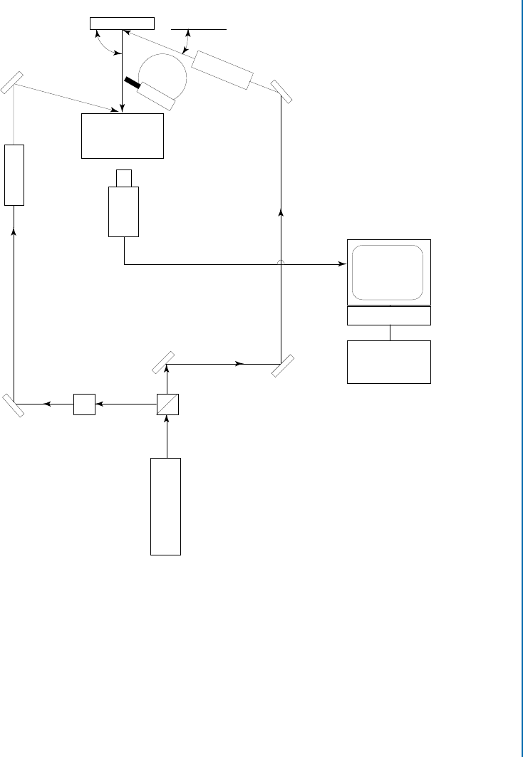
Figure 7.1 illustrates the holographic technique used for hole-drilling measurements. It
is a variant method that makes a hologram by exposing a thermoplastic recording plate to ref-
erence and scattered object light and then developing the plate. After hole-drilling the plate is
exposed again to the same light sources. e hologram then displays a pattern of live light and
dark “fringes” that resemble a contour map. Figure 7.2 illustrates an example holographic fringe
pattern. e fringes indicate lines of constant surface displacement between holographic expo-
7.2. HOLOGRAPHIC INTERFEROMETRY 145
Test Object
M
M
M
M = Mirror
C = Collimator
M
M
C
C
Drill on
Rotary Base
Variable
Beam Splitter
Argon
Laser 0.6 W
(λ = 0.515 µm)
Object
Beam
Reference
Beam
Attenuator
Video Camer
a
Video Monitor
γ
1
γ
2
Holocamera
Video Copy
Processor
VCR
Figure 7.1: Example optical arrangement for making holographic hole-drilling measurements
(from Nelson et al. (1994)).
sures. e displacement interval between fringes is a fixed value that depends on the wavelength
of the illumination light and the geometry of the illumination arrangement used. e example
pattern is unsymmetric because the sensitivity direction of the measurement is inclined to the
right, midway in direction between the incident and reflected beams at the test object surface.
e apparatus in Figure 7.1 consists of a laser source to provide the required coherent
monochromatic illumination. A beam splitter divides the output into two separate beams, the
..................Content has been hidden....................
You can't read the all page of ebook, please click here login for view all page.