
6.2. PRACTICAL STRAIN GAUGE ROSETTE INSTALLATIONS 127
a hole of diameter 0.4D drilled to a depth of 0.2D in an equi-biaxial stress field, the stress
relaxation at a distance of 2.4D is less than 1% of the stress originally at the hole. Accord-
ingly, it is recommended that the minimum distance between adjacent holes dg
min
should
be at least 2.4 times the gauge diameter D.
Some further factors that need to be considered when planning measurements include the
following.
• Drilling machine accuracy. e Hole-Drilling Method requires making strain measure-
ments after each of a sequence of hole depth increments. e accuracy of the subsequent
residual stress evaluation directly depends on the dimensional accuracy of the hole depth
increments, which in turn depends on the quality of the cutter position control during the
drilling process. is issue becomes more of a concern when using many small hole depth
increments (10–25 are typical) and when using very small rosettes. In the latter case the
required hole diameter and depth increments vary in proportion to the rosette size, and so
a greater absolute accuracy is required to maintain a reasonable level of relative accuracy
of the drill depth increments and the concentricity of the drill within the rosette. us,
while the smallest 1/32” rosettes may appear attractive to fit in sites with restricted area
or on thin, curved specimens, they can be less practical because of their more demanding
drilling accuracy, handling and soldering requirements.
• Number of gauges to be installed on the specimen. As noted above, the stress relaxation
effects of hole-drilling extend over areas of the specimen beyond the immediate area cov-
ered by the target gauge. Accordingly, where it is required to install and drill a large number
of gauges within a restricted surface area, the limit on between-hole distance dg
min
spec-
ified in Table 6.1 can be met by using smaller rosettes, but with the caution noted above.
In addition, where a mix of large and small gauge sizes are to be applied to a specimen in
close proximity to each other, planning for the sequence of measurements should consider
the installation and drilling of the smaller gauges (with smaller diameter holes) prior to
the larger gauges.
Where the installation of the gauge on the specimen surface differs significantly from the
above specifications, detailed finite element models of the specimen (incorporating the drilled
hole) can be used to quantify the strain response of the residual stresses. However, useful com-
parative information can often still be gained from processing non-compliant strain data using
the standard Integral Method coefficients. For example, comparison of results from two or more
differently processed specimens can indicate large differences in residual stresses even though
the results are not strictly quantitative.
128 6. EXAMPLE PRACTICAL PROCEDURES AND RESULTS
6.3 ORIENTATION OF TYPE B STRAIN GAUGE
ROSETTES
e one-sided arrangement of Type B rosettes enables hole-drilling measurements to be made
on specimens at locations close to edge and step features. However, the use of such gauges re-
quires careful consideration prior to installation to achieve the best possible results. e layout
of gauge elements and row of solder tabs appears to invite the user to install such a gauge with
the “long” side of the rosette parallel to the edge or step feature. is direction commonly corre-
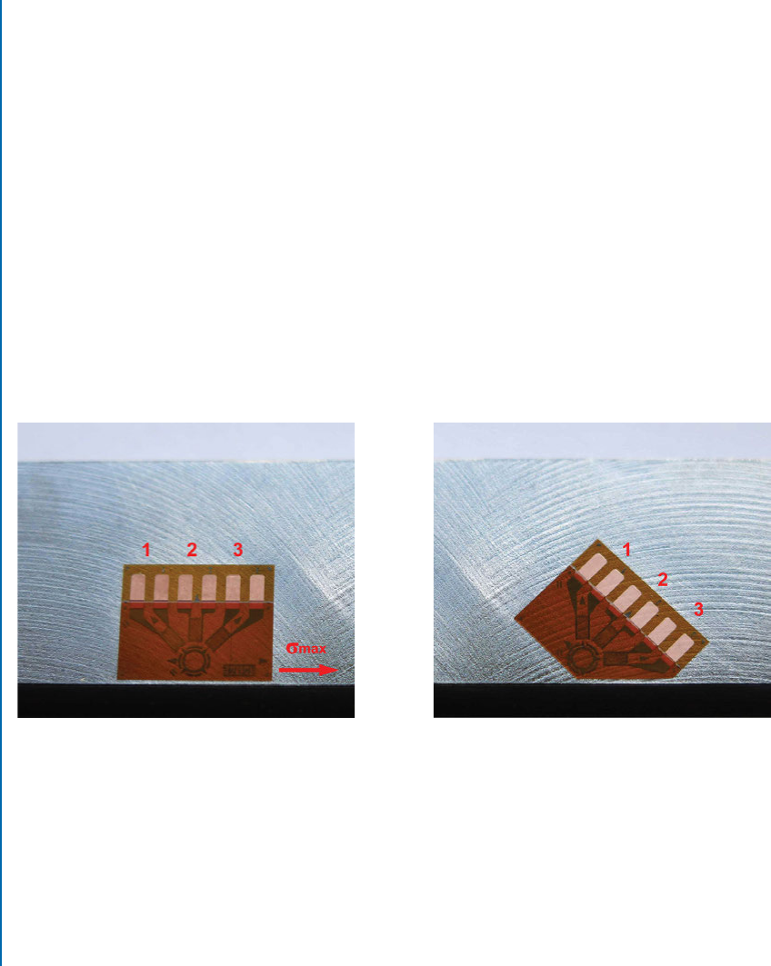
sponds to a principal strain direction. Figure 6.7a shows such a direct installation. In this case,
the minimum principal strain is perpendicular to the edge and the maximum principal strain is
parallel to the edge. is arrangement is non-ideal because only one strain gauge (number 2)
is aligned in a principal direction. e strain required for the computation of the stress
max
in Figure 6.7a can be calculated from combining the strains from gauge elements 1, 2, and 3.
However, consideration of the Mohr’s circle for this “worst” alignment case demonstrates that
the resulting uncertainty in
max
can be up to 3 times that found when the principal strains are
aligned with gauges 1 and 3.
(a) Type B gauge aligned with edge (b) Type B gauge; inclined installation
Figure 6.7: Type B gauge at an edge feature; direct installation (images courtesy of Stresscraft
Ltd.).
In practical terms, such an amplification of uncertainty can add an unacceptable level of
noise to the subsequent stress computation. is problem can be avoided by trimming some of
the gauge backing material and re-orientating the rosette so that one of the gauge elements is
aligned with the edge feature. Figure 6.7b shows such an installation; for this revised installation,
uncertainties in both the principal strain directions are minimized.
..................Content has been hidden....................
You can't read the all page of ebook, please click here login for view all page.