

3.5. DEFORMATION MEASUREMENTS 53
action similar to that in Figure 3.6 substantially helps. Because of the imperfect hole shape, the
air-abrasive method is suitable only for measurements of uniform residual stresses.
An alternative “hole-drilling” procedure is by Electro-Discharge Machining (EDM) us-
ing an electrode with shape corresponding to the desired hole cross-section. e EDM technique
has similar advantages to the air-abrasive technique in that it can work with very hard materials,
but great care is required to minimize the thickness of the “re-cast layer” formed during the pro-
cess. Electrochemical Machining (ECM) is another possible method of forming a blind hole
that can proceed in an entirely stress-free manner, but control of electrolyte in close proximity
to the strain gauge is problematic. Air-abrasive, EDM and ECM methods all require rather
specialized equipment, so have only specialized use.
Contemporary hole-drilling equipment and practices have developed and continue to de-
velop in many details from their historical predecessors. Figure 3.7 illustrates some contemporary
hole-drilling equipment. e use of such devices has greatly enhanced the ease and range of use
of the hole-drilling method.
(a) (b)
Figure 3.7: Modern hole-drilling devices. (a) Vishay RS-200 with air turbine (reproduced by
permission of Micro-Measurements, a Vishay Precision Group brand) and (b) SINT drilling
device (reproduced by permission of SINT Technology s.r.l.).
3.5 DEFORMATION MEASUREMENTS
From an early stage, the mechanical extensometer used by Mathar was recognized as a major
factor limiting the accuracy and reliability of hole-drilling residual stress measurements. e
development of strain gauges in the 1940s enabled substantial improvements to be achieved in
54 3. HOLE-DRILLING METHOD CONCEPT AND DEVELOPMENT
deformation measurement quality. In 1950, Soete introduced the use of strain gauges for hole-
drilling measurements, greatly improving measurement accuracy and reliability, and allowing
smaller holes to be used. At that time, strain gauges were still in their infancy and their use
required specific consideration to fit the needs of each intended application. Modern process-
ing techniques for thermal stabilization had not yet been introduced, so thermal stability of
the strain gauges was a particular concern. is concern was addressed by using multiple strain
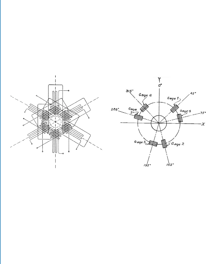
gauges in half or full bridge configurations. Figure 3.8 shows some early strain gauge rosette ar-
rangements, designed to give a three-axis measurements with full thermal compensation. ese
designs are interesting from an historical point of view for the insight they give into the concerns
and challenges facing early strain gauge practitioners.
(a) (b)
Figure 3.8: Early hole-drilling strain gauge rosette designs with thermal compensation. (a) Ri-
parbelli (1950) and (b) Riparbelli (1958).
Several of the early researchers, notably Soete and Vancrombruge, Riparbelli; Boiten and
ten Cate; Kelsey; Rendler and Vigness; and Bathgate, pioneered the use of strain gauges for hole-
drilling residual stress measurements. In general, they adapted general-purpose strain gauges for
hole-drilling use. is involved very careful placement of the strain gauges to achieve an accurate,
symmetrical arrangement around the intended hole location.
e work of Rendler and Vigness (1966) can be considered the foundation of the modern
strain gauge hole-drilling practice through their introduction of preassembled rosettes using a
standardized strain gauge geometry. e custom design and precision construction of the rosettes
provide much superior performance compared with the early hand-assembled strain gauges. In
3.5. DEFORMATION MEASUREMENTS 55
addition, Rendler and Vigness recognized that the measured strain response depends only on the
relative sizes of the rosette components and the hole, independent of their overall dimensions.
us, all rosette and hole dimensions can be scaled up or down as desired to suit experimental
needs. ese developments advanced the hole-drilling method into a practical procedure that
could be used by general practitioners.
e work of Rendler and Vigness provided the basis for the establishment of ASTM
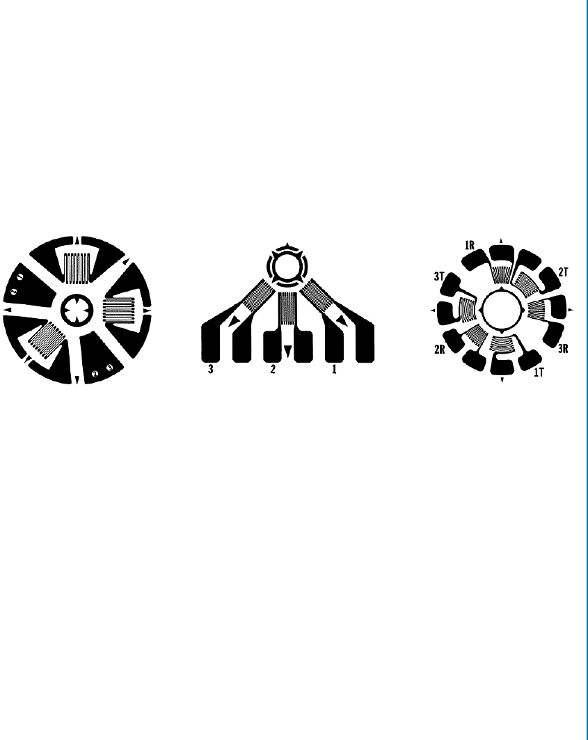
Standard Test Method E837 in 1981, updated and expanded several times since then. Fig-
ure 3.9 shows the standardized strain gauge rosette designs specified by E837. e geometry
of the “Type A” pattern corresponds exactly with the original Rendler and Vigness design and
is available in three different sizes. e 1/8” and 1/16” sizes come directly from Rendler and
Vigness’s work, the smaller 1/32” size was added subsequently.
Type A Type B Type C
Figure 3.9: Standardized hole-drilling strain gauge rosettes (reproduced by permission of Micro-
Measurements, a Vishay Precision Group brand).
e “Type B” rosette in Figure 3.9 is a variant geometry, designed for use near a boundary
or obstacle. e “Type C” rosette is a more specialized design intended for use on low ther-
mal conductivity materials or where the local residual strains are very low. is rosette pattern
achieves in modern format the thermal compensation objective anticipated in the 1958 Ripar-
belli rosette design shown in Figure 3.8b.
Since their introduction in the 1950s, strain gauges have been the standard sensor used
for measuring surface deformations when making hole-drilling residual stress measurements.
ere are many good reasons for this; they are convenient to use, they give reliable and accurate
measurements and the supporting instrumentation is widely available at moderate cost. ese
factors have combined with the conceptual simplicity and generality of the hole-drilling process
to make the Hole-Drilling Method one of the most commonly used residual stress measure-
ment methods. However, this is not to imply that strain gauges are the only sensor choice, nor
universally the ideal choice.
Starting in the 1980s, full-field optical methods based on interferometry were introduced
for hole-drilling residual stress measurements. Such methods are attractive because they display
56 3. HOLE-DRILLING METHOD CONCEPT AND DEVELOPMENT
a detailed map of the deformations around the drilled hole and because they avoid the need to
attach strain gauges on the specimen surface.
Initial optical developments were made using interferometric Moiré and holographic
techniques. In the 1990s, a variant technique called Electronic Speckle Pattern Interferome-
try (ESPI) also started to be applied to hole-drilling measurements. e ESPI technique uses a
digital camera to record the optical images and is attractive because it eliminates the need for a
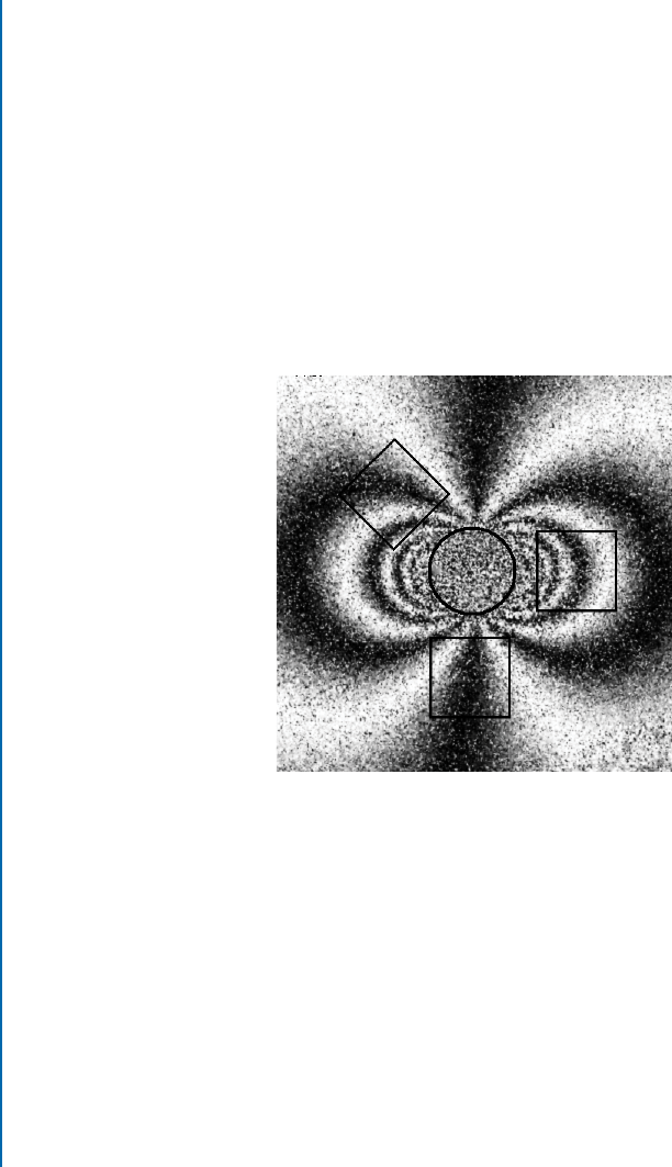
thermoplastic or similar recording device used by the holographic method. Figure 3.10 shows an
example of an ESPI measurement. e light and dark lines are called “fringes” and the intervals
between them represent incremental surface displacements of a fraction of the wavelength of
the light used, the exact fraction depending on the interferometer geometry. All interferomet-
ric techniques make measurements at the scale of the wavelength of light, 400–700 nm in the
visible range, so they are highly sensitive and can detect very small surface displacements.
Figure 3.10: A typical ESPI fringe pattern from a hole-drilling measurement. e circle and
squares, respectively, show the hole and equivalent strain gauge locations.
Starting in the 2000s, the popular Digital Image Correlation (DIC) technique started to
be applied to hole-drilling residual stress measurements. It has the advantage of being more
tolerant of field conditions than the interferometric methods, although for conventional size
holes in the 1–5 mm range, it is less sensitive. However, with care, satisfactory results can still
be achieved.
DIC differs in an important fundamental way from the interferometric methods. e
latter are scale-dependent because their measurements are produced relative to the wavelength of
the light used. us, they work best with macro-scale holes, typically with diameter greater than
about 0.5 mm. In contrast, DIC measurements are scale-independent because their sensitivity
is controlled solely by the pixel dimensions and the feature density of the measured images,
..................Content has been hidden....................
You can't read the all page of ebook, please click here login for view all page.