
4.3. GAUGE INSTALLATION 75
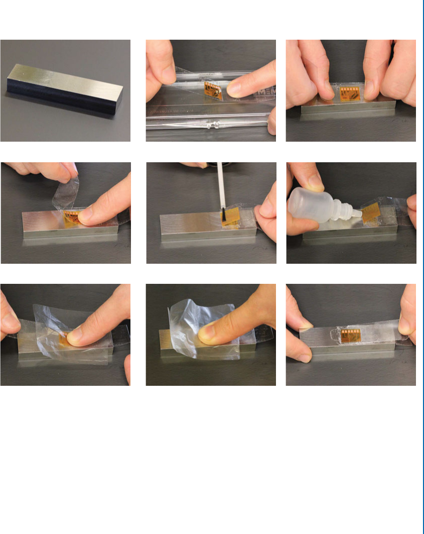
i) Remove the tape by carefully peeling back (at acute angle to reduce lifting of the rosette;
Figure 4.4i).
(a) Prepared specimen (b) Rosette and tape (c) Positioning the rosette
(d) Rosette/tape peeled back (e) Application of catalyst (f ) Application of adhesive
(g) Rosette rolled into position (h) Application of pressure (i) Removal of tape
Figure 4.4: Target strain gauge installation on a test specimen (photos courtesy of Stresscraft
Ltd.).
e installation can then be carefully wiped using a solvent to remove any excess adhesive
and closely inspected.
Further details, including handling precautions for the materials involved in the applica-
tion process, are described in Micro-Measurements Bulletin B-127-14. Some adaptation of the
procedure may be required for less straightforward installations.
76 4. STRAIN GAUGE TECHNIQUE: METHOD DESCRIPTION
4.4 INSTRUMENTATION AND ELECTRICAL
CONNECTIONS
Several portable and laboratory-based strain measuring and recording instruments are com-
mercially available and are suitable for use with hole-drilling. ASTM E837 stipulates that the
instrumentation for recording strains should have strain resolution, stability and repeatability all
within ˙ 2 ". Most modern strain gauge instrumentation has the required resolution and sta-
bility for measuring the small strains in incremental hole-drilling. A minimum of three channels
is required, one per gauge element or element pair. Continuous excitation of all channels is de-
sirable because it avoids possible transient response and extended settling time as each channel
is energised for strain gauge reading. For work on poor conductors or thin plate test specimens,
continuous excitation offers the advantage of allowing any heating effect from the gauge exci-
tation current to attain a steady state prior to commencement of hole drilling. Because of the
time required for drilling each increment, there is no need for a very fast acquisition rate.
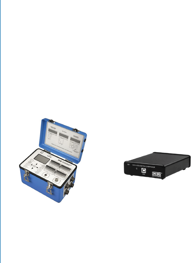
Figure 4.5 shows examples of instruments that can offer the required strain resolution,
stability, and repeatability. ey feature four channels that can be configured as quarter, half or
full bridges. Instruments from other manufacturers that have similar features can also be suitable.
(a) Vishay P3 Strain Indicator and Recorder (b) Vishay D4 Data Acquisition Conditioner
Figure 4.5: Examples of strain measurement and recording instruments (reproduced by permis-
sion of Micro-Measurements, a Vishay Precision Group brand).
It is usual for electrical connections between the gauge and recording instrument to be
made with the specimen fixed in the location where the hole drilling procedure is to be carried
out. While not essential, this practice avoids placing any undue strain on soldered joints and
gauge bonds from extraneous movements to and from the measurement location. Specimens
..................Content has been hidden....................
You can't read the all page of ebook, please click here login for view all page.