
Chapter 15. The Finite State Machine
Who changes his condition changes fortune.
—Italian proverb
Condition makes, condition breaks.
—Scottish proverb
In this chapter we get down to the meat of describing the dynamics of the problem solution. The most basic tool for doing that in MBD is the finite state machine (FSM). The FSM is probably the most elegant and important general mathematical tool applied to software development.1 More important, it is extraordinarily applicable to OO development. That’s because the rules for FSMs explicitly enforce basic OO principles. We would be hard pressed to design a tool that provides the same degree of rigorous enforcement of things like encapsulation, implementation hiding, separation of message and method, and peer-to-peer collaborations.
As an added bonus, the asynchronous assumptions underlying FSMs fit very nicely into the context of OOA modeling where we need to be independent of specific computing environments. As has already been pointed out several times, an asynchronous description is the most general description of behavior. Since FSMs can only interact asynchronously, using them forces us to develop an OOA model of solution behavior that is independent of the computing environment and has no hierarchical implementation dependencies—just as we should.
The rest of this chapter is devoted to the basics of identifying FSMs in the problem space.
Basic Finite State Automata
The underlying mathematics for FSMs is Finite State Automata (FSA). In an FSA there are three essential elements:
- State. This is a unique condition where a specific suite of rules and policies apply. In an FSA those rules and policies determine how an input alphabet is to be processed in that state. An important rule for FSAs is that the rules and policies at a given state may not depend in any way on what the previous state was or the next state will be (i.e., they are self-contained and only depend on the alphabet and the condition). Diagrammatically, an FSA state is traditionally shown as a circle that is labeled with a unique state identifier.2
- Transition. This is just a change in state indicated by an arrow from the current state to the new state. Triggering a particular transition is controlled externally to the FSA itself; the FSA just enforces the rules for valid transitions from a given current state.
- Alphabet. The mathematical definition is a bit arcane, but for our purposes we can think of the alphabet as some set of input values provided when the transition is triggered. The rules and policies of the new state operate on the input values. If there are multiple transitions into a state, then they must all have the same alphabet. Diagrammatically the alphabet is usually an enumeration of variables attached to the transition.
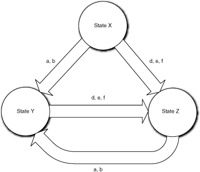
Figure 15-1 illustrates a simple FSA. Note that state X cannot be reached from either of the other states—a classic case of you-can’t-get-there-from-here. This is rather unusual for software situations, particularly object life cycles, but it is occasionally seen.
Figure 15-1. Example of an FSA life cycle with constraints on the sequences in which states may be accessed
In FSAs there are some assumptions that cannot be realized in real software. The FSA is always in some state (i.e., the transition is instantaneous). Similarly, the rules and policies that process the alphabet take no time to execute. Finally, the rules and policies operate only on the input alphabet (i.e., there is no persistent data in the FSA). The main differences between FSMs, as applied in OO development, and FSAs lie in the handling of these assumptions.
The basic definitions of state and transition remain the same. The notion of alphabet, though, is considerably expanded to include state variables (the knowledge attributes of objects) that are persistent across states. This is necessary to address the fundamental dichotomy of object abstraction in terms of both knowledge and behavior. Since knowledge is accessed synchronously in OOA/D, accessing attributes is not significantly different than accessing input parameters as long as the processing is self-contained.3
Since the notion of accessing knowledge includes the possibility of modifying it, the scope of activity of the alphabet processing is greatly enlarged by this expansion of the idea of what an alphabet is. That’s because the processing can modify knowledge attributes in addition to providing an alphabet for outgoing transitions. That immediately introduces issues around data integrity in real software. One of the reasons that OO development emphasizes things like encapsulation, abstracting intrinsic responsibilities, and peer-to-peer collaboration is to better manage data integrity by managing the scope of change. This is in part why the FSA paradigm is so useful—it limits the scope of the rules and policies that are executed in a state by ensuring they are self-contained.
An action implements the rules and policies associated with the state condition. A state machine action is an object method.
In an FSM we encapsulate business rules and policies in an action. The action’s processing is that associated with the particular condition’s rules and policies. That containment of processing is very important when it is time to implement things like concurrent processing because it rigorously defines the scope of change.4 That containment is further enhanced by the introduction of a conceptual infrastructure to support object FSMs: the event queue. The introduction of an event queue decouples actions from one another.
An event is a message that announces some change in conditions within the overall software solution.
Events are FSM artifacts that are associated with transitions. Technically an event announces some change in the condition and that announcement triggers a transition. We need events because we have multiple interacting FSMs in a typical OO subsystem, so that quasi-mystical “external trigger” of the FSA is quite concrete in an OO subsystem. It actually originates in another object FSM with its own state conditions to worry about. In addition, we need some mechanism for passing around the alphabets from one object FSM to another. So, we introduce the interpretation of event as a message between FSMs that triggers transitions, and the event message’s data packet represents at least part of the alphabet.
What about the assumptions of instantaneous transitions and actions in the FSA? So glad you asked, Grasshopper. That is, indeed, a conundrum, because software actions require finite time to complete. Also, in an asynchronous model we could potentially have the state machine processing two actions at the same time if the events appeared quickly. The answer is the event queue. All events directed to the FSM are enqueued by the event queue manager for later processing. The event queue then “pops” the events one at a time to ensure that the FSM only consumes one at a time (i.e., the event queue manager waits until the object FSM has completed any current processing before popping the next event from the queue). This very neatly gets around the finite execution time problem for state actions because the event queue manager serializes5 the processing to ensure the state machine doesn’t step on itself.
However, the event queue manager is really an implementation issue. Typically it will be a reusable library class and the details of instantiating it will be determined by nonfunctional requirements. Therefore, we need to raise the level of abstraction and never explicitly create EventQueueManager objects in an OOA model. The concept is abstracted in the idea of events as special messages and in certain assumptions the developer can make. Then the event queue manager is just an implementation infrastructure to support the message passing concept. There are assumptions the developer can make when designing collaborations.
- Only one event at a time is consumed by a given FSM. The event queue in the implementation takes care of this, so the developer can rely on this assumption.
- Multiple events from the same sender FSM to the same receiver FSM will be consumed in the same relative order that they were generated. This is crucial to proper management of data integrity in an asynchronous behavior model with state variables; without this rule the developer’s mind will tend to boggle. It can occasionally be a pain for the transformation engine to enforce, but we simply can’t live without it.
- Self-directed events will be consumed before external events directed to same FSM. Self-directed events are generated by an FSM to itself. They are often a symptom of poor design, which will be addressed later. However, there are some rare situations where they can be useful, and this rule is necessary for those situations. Thus the developer can rely on this prioritization within the event queue manager.
Note that the introduction of event messages is quite consistent with the OO separation of message and response (method). In an object FSM, the event is a separate model element that is associated with the transition. In fact, we can fully design object FSMs without considering events at all and then, in a later pass, we can determine where events are generated and associate them with the relevant transitions.
One interesting implication to underscore the distinction between event and transition is that we could associate the same event with multiple transitions in the FSM. This means that the response to the message (i.e., condition rules and policies to be executed) could be different depending on what the current condition of the object is. In effect we have the potential for behavior substitution without the subclassing infrastructure usually associated with inclusion polymorphism—it is done within a single object! This sort of substitution is not possible in a pure FSA model because only the alphabet is defined for the transition, not an identifiable event.
There is one final issue that was discussed briefly in the part road map: Exactly when is the action executed? In a pure FSA, it is executed on entry to the state. An FSM that has the same rule is known as a Moore FSM (known in UML as a behavioral state machine). As indicated in the Part III road map, there is a theoretical conundrum related to finite action execution time. The people who worry about such things came up with the Mealy FSM (known in UML as a protocol state machine), whereby the action is associated with the transition and it is executed when the event that triggers the transition is consumed.
Alas, there are other deeply philosophical OO issues at stake because of the implications of the Mealy model in an OO context. Mealy is just not a good fit with basic OOA/D technique. In the Mealy model the key implication, which is supported by many OOA modeling tools, is that we could have different actions on different transitions targeting the same new state. If we have gone that far, then we could have different alphabet parameters for those actions. That is pretty far removed from the original FSA definition. In particular, it pretty much trashes the fundamental state definition that it is a condition where a unique set of rules and policies always apply. In effect the Mealy view says that there are multiple sets of rules and policies that might apply.
However, that is not the big problem with Mealy. The real concern is with how we select a particular set of rules and policies from among the alternatives to be executed when the state is entered. They are selected based upon the context (i.e., the particular transition/event).6 Alas, one of the fundamental rules of FSAs is that the rules and policies can’t depend on what the last state was. At this point it seems that the theoretical mapping to FSA theory is getting pretty thin indeed. But the back-breaking straw is that it opens a Pandora’s box of temptation in an OO context by enabling the action to be mapped directly to the event.
In an OO context events are supposed to be messages that announce some change in the state of the application. The OO paradigm separates message and method precisely so that those announcements can be made with no expectation of what will happen. This enables the behavior implementation where the event is generated to be independent of what will happen as a result. But if we map the resulting action directly to the event, that decoupling goes away. There is now an explicit expectation of what will happen when a particular event is generated. That is a very procedural mindset that invites one to create implementation dependencies in the sender implementation. Removing that temptation is why...
In MBD we only use the Moore model for object FSMs.
For the previous discussion we need to clarify the difference between a condition in an object FSM and a condition of the overall solution. Since the object has a much narrower focus than the overall solution, object FSM states tend to be subsets of the overall solution’s conditions. In general, the DbC postcondition of an FSM action maps closest to a condition of the overall solution. However, the overall solution includes things like data integrity constraints for every attribute in the entire application, most of which are irrelevant to a particular object’s responsibilities.
Notation
Figure 15-2 represents the graphical view of a State Transition Diagram (STD) in UML, which is the traditional name for such diagrams. It is called a statechart in UML. The state is represented as a box with rounded corners that is divided into two sections. The state condition identifier is placed in the upper section of the box. A natural language description of the state goes in the lower section. In MBD this is usually a natural language pseudocode for what the action does. (Most tools enable the description view to toggle between the natural language description and the actual abstract action language [AAL] specification for the behavior, but we’ll deal with that later.)
Figure 15-2. Relationship of events to state machine transitions
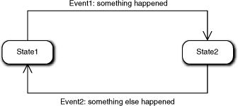
The arrows in Figure 15-2 represent the allowed transitions. The event that triggers the transition is associated positionally with the transition. It has a unique identifier and a mnemonic description of the event. Generally, we do not include the passed input values in the event message in MBD, although most tools allow that. There are a several reasons for this, including that the alphabet tends to clutter the diagram. Another reason is that we usually apply MBD with tool support and the full event description is just a click away. The main reason, though, is that we look at the Statechart diagram to view the solution flow of control. At that level of abstraction the specific arguments are peripheral details.
There is a special situation that applies when an object is created and must be placed in an initial state. This is a one-time event in the life cycle, and it is sometimes known as a “create” event. This is represented by a “floating” transition into a state that has no source state. The floating end is terminated with a small solid circle. We also use this notation to indicate a set of transitions from substates, as in Figure 15-3.
Figure 15-3. Equivalence of superstate notation to peer states
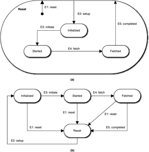
Figure 15-3 represents one variation of representing state machines that is worth discussing: superstates. The notion of superstates was originally expounded in the Harel model for FSMs. As indicated in the previous chapter, MBD does not employ the Harel model. However, we do provide a superstate artifact that is handy for reducing diagram clutter. As shown in Figure 15-3(a), a Reset state performs an action to reset some test hardware. The main structure indicating a basic life cycle progression7 is: Reset → Initialized → Started → Fetched → Reset.
The problem is that the E1:reset event can be issued at any time to halt the current sequence, which results in a transition back to the Reset state from every other state. There are two reasons why it is advantageous not to draw those transitions explicitly. One is the clutter of the additional transition lines in the diagram that distracts us from the important processing and sequencing constraints. In a simple example like this that is no big deal, but in a more complicated FSM we would have ugly crossovers and whatnot for the transitions. More important is that the E1: reset event will only get issued when some sort of exceptional situation arises in the external world (i.e., the normal return to Reset is just from Fetched via E5:completed). Thus the top diagram clearly shows the normally expected life cycle without any distraction for rare scenarios.
It must be emphasized that this is not the Harel view of superclasses. In Harel, the Reset state would probably be called something like Active and it would have some behavior that was executed when any of the E2, E3, E4, or E5 events was processed, such as ensuring that a port connection to the hardware was available. That is, the superset state would have some unique behavior shared by all of the contained substates. In the MBD approach that is not the case. Reset is just another state in the life cycle, with its own unique rules and policies that only get executed when a transition is explicitly made to it. The superstate is basically a pure notational artifact to reduce the number of transition lines necessary on the diagram. Thus part (a) in Figure 15-3 is semantically equivalent to part (b).
There are a couple of commonsense conventions necessary for properly interpreting an MBD FSM with superstates:
• Events from all contained substates to the superstate are indicated with a “floating” event with an origin inside the superstate. The E1:reset event is an example.
• Create events that set the initial state of the FSM to the superstate when the object is instantiated are represented as “floating” events to the superstate whose origin is external to the superstate.
• Events to the superstate from only one or a subset of substates should be shown explicitly because they are not common transitions for all substates. The E5:completed transition is an example where it is only valid if the FSM is in the Fetched state.
• Events from the superstate to one or a subset of substates should be shown explicitly because they are not common for all substates. The E2:setup transition is an example to show the only way out of the Reset state.
Essentially these rules simply remove any ambiguity about whether a particular transition is common to all substates or not.
The state machine structure can also be described in tabular format in a State Transition Table (STT) as shown in Table 15-1. The rows are the current state while the columns represent the possible events that the object will accept at least some of the time. The cells have three possible entries: the new state, if the event results in a valid transition; “can’t happen,” if the event is not valid for the current state; and “ignore,” which means the event will be consumed but no transition takes place and no action is executed.
Table 15-1. FSM View of State Transition Table
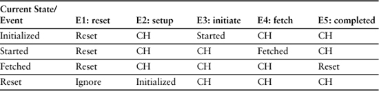
The FSM view of the STT is somewhat different than a classical FSA STT because it is not possible to ignore an event in an FSA. We include Ignore in MBD because the notion of a message being relevant to an object some of the time turns out to be a fairly useful feature. A classic example of this is the OS window manager for a GUI that generates a gazillion WM_MOUSE_MOVE events as a spastic user moves the mouse when the cursor is in hourglass mode. This enables the object to traverse several states where it doesn’t care about mouse movement until the task in hand is completed, so it ignores them. But when the task is completed it transitions to a state where the hourglass is turned off, and it is ready to accept the movement events and respond appropriately.
Note that this notation is almost childishly simple. Yet FSMs are enormously powerful tools for describing behavior in an OO context. Effectively using that power requires that we appreciate the elegance with which FSMs enforce OO principles. Most of the rest of this chapter and the next will be devoted to showing how to think about FSMs so that the power is unleashed.
The Role of Design by Contract (DbC)
Long before OO development, the notion of software contracts between client and service was introduced to facilitate modularization and API design. In the ’80s, DbC was formalized for OOPLs in terms of inline correctness assertions for method preconditions, postconditions, and invariants. These were defined as:
• Precondition. Some set of testable conditions about the inputs and state variables that must prevail before the method can execute. Basically, a precondition tests whether the overall state of the application is ready for the method to execute.
• Postcondition. Some set of testable conditions about outputs and state variables that must prevail after the method completes. Basically, postconditions test whether the overall state of the application is correct after the method completes doing its thing.
• Invariant. Some set of testable conditions about state variables that must prevail for the entire time the method executes. Basically, an invariant tests whether the overall state of the application is consistent throughout the time the method is executing. As a practical matter, invariant assertions were only written for the state variables that the method touched (i.e., a “white box” view).
As it happens, preconditions and postconditions are enormously important to FSM interactions. In some cases a DbC analysis is the only practical way to get them to play together properly. However, we use a somewhat different spin on DbC in an FSM context. At the 3GL, level correctness assertions are primarily focused on ensuring data integrity, while in OOA models we also use them to validate timing.
We use DbC to design FSMs and collaborations.
One way the difference in views is manifested is that in MBD we view a precondition as the condition that must prevail for the method in hand to execute rather than as a constraint on inputs. Since part of that precondition for execution is that the required inputs are available and consistent, the views are equivalent in that respect. What MBD adds to the notion of a precondition is algorithmic sequence. Our notion of precondition includes the position of the method among the many individual steps of the overall problem solution.
In a Moore model, an FSM state is identical to a DbC postcondition. The FSM state represents a condition where the action’s rules and policies prevail, which is the same as saying it is the postcondition for executing the action on entry to the state. Since an FSM state change is triggered by an event generated in a different FSM action and we think of events as announcements of some state change, the postcondition of the action generating the event must be the precondition for the responding action. This enables a very rigorous technique for determining where events should be generated and where they should go.
Conceptually, the technique is trivial. We just have to compare the precondition of the state in hand to the postconditions of other states and, when a match occurs, generate the event in the action of that matching postcondition. The tricky part lies in properly determining the precondition of the state in hand. That precondition has two elements:
- The behavior responsibilities that must execute before the behavior in hand in the overall solution flow of control
- The attribute values needed by the method and the criteria for their timeliness and consistency. (Essentially this is the traditional DbC view of the OOPLs.)
As a practical matter, for the first element it is usually easier to identify the last responsibility to execute in the flow of control that is a prerequisite for the execution of the method in hand. Unfortunately, that is not always so easy. The reason is that the elements are not as independent as they might seem.
Consider a method that accesses six different attributes. Each of those might be owned by a different object. More to the point, they may be set in six different methods. In effect, executing each of those setting methods becomes a prerequisite for executing the method in hand. In addition, there may be several methods that modify attributes those setting methods need. So which one is the last method that needs to execute before the method in hand? To figure that out, we need to work backwards and reconstruct the entire chain of data updating dependencies. That sort of backtracking would be a challenge for a grandmaster-level chess program.
Use a UML Sequence diagram to keep track of dependencies when resolving DbC flow of control.
However, it gets a whole lot easier if you have already resolved some of the preconditions of other methods. It also gets easier if we have a convenient format for keeping track of those dependencies and for thinking about flow of control in the large. The tool for doing that is a UML Sequence diagram. If you are modifying flow of control in an existing application, figuring out how to do it can literally take just a few seconds if you have a Sequence diagram from before the change.8
When you are initially defining the flow of control, it is recommended that you use a white board9 Sequence diagram to keep track of what you are doing. For that the following process is useful.
- Start with an external subsystem input event. The action that processes that event becomes your starting point.
- Take a guess at what action should be executed next in the flow of control sequence from the action where you are. If there are no actions left without trigger events, you are done.
- Determine the precondition for executing the action identified in step 2.
- Compare that precondition to the postcondition of the action in hand. If satisfied, the action identified in step 2 becomes the action in hand and you go back to step 2. Otherwise, you go back to step 2 and make a different guess.
The value of this approach is that the backtracking to reconstruct chains of data dependencies is largely eliminated. That’s because the approach takes advantage of the fact that you already have a pretty good idea of how the application flow of control should work at the object collaboration level; thus the guess at step 2 is a very educated guess. In addition, wherever you are in the process, you already have documented a bunch of known dependencies in the Sequence diagram, so you already know what the last action to execute is.
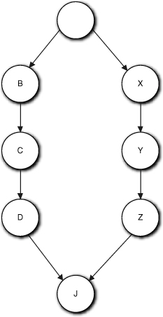
Alas, there is still a problem. You could have two sequences of processing that start at the same point but are essentially independent. Such sequences are represented schematically in Figure 15-4. Using this approach as is will tend to lead you down one of those sequences until you reach a “join” point, J, where the action to execute will depend on the last action of both threads (D and Z). If you traverse the {B, C, D} sequences first, then the precondition for J will not be satisfied by D alone, and we are faced with figuring out that Z is the last other action. To avoid that, try to do a breadth-first “walk” by checking whether there is more than one “next” action at each action. That is, check whether there is more than one valid guess in step 2 (e.g., B and X in the figure). If so, validate and keep track of each one before moving on to a new action.
Figure 15-4. Example of dependence on completion of multiple processing sequences
Besides the rigor that can be used to validate collaborations, DbC is important because it raises the level of abstraction of collaboration. It enables us to design state machines and describe their actions without worrying about generating events. In theory, once object FSMs are defined, we could backfill the collaborations at the UML Interaction diagram level to encode the overall solution sequencing using DbC to determine the message events.
Looking for State Machines
This is unquestionably the toughest part of MBD for newcomers. Even if we don’t buy the conventional wisdom myth described in the Part III road map, it is usually tough for developers to identify FSMs in the problem space if they have never worked with state machines before. It is even more difficult to abstract them correctly.
As indicated in the road map, there are two issues that must be resolved: whether the object has true problem space behaviors (i.e., that the responsibilities are not better thought of as knowledge accessors) and, if so, whether there are fixed sequencing constraints on their execution in the problem space. The rest of this chapter is devoted to guidelines on how to resolve those issues.
Knowledge versus Behavior
The first task in developing state machines is to identify what knowledge is and what behavior is. As the Part III road map indicates, synchronous services are a form of behavior but they are very restricted; they are essentially operations on knowledge properties already defined as attributes. So we have an early decision to make: Do we represent the problem space in terms of knowledge that we manipulate using synchronous services, or do we represent the problem space in terms of pure behaviors whose sequencing we manage with state machines?
Alas, this is not always a clear decision. This is best illustrated by considering what may be the simplest possible example: an On/Off indicator on a machine that must be green when the machine is On and must be red when it is Off. You no doubt recall that in the Part III road map we said that we use FSMs to capture sequencing rules in the problem space. In this case there seems to be a sequencing rule: When the light is green, the only possible change is red, while if it is red, the only possible change is to green. Does this mean we need to capture that sequencing in an FSM?
In this simple case the answer is probably not. If we had to have an FSM for every possible data value change, our models would be terminally cluttered for no useful purpose. The real issue here is the nature of the responsibility. Is the color of an On/Off indicator inherently knowledge (its current color) or behavior (some activity important to solving the problem)? Intuitively, an On/Off indicator seems like a pretty inactive object in the scheme of the overall solution, and changing the color doesn’t seem to have an associated activity that is crucial to the overall problem solution flow of control. (Writing to the hardware to physically change the color would probably be a behavior, though, if different instructions were required for each color.)
However, if we implement this object as a dumb knowledge holder with nothing to actually do, we may still have a problem. If we provide a synchronous setter like setColor(color), then we move the rule for determining the color to some other object. In effect, ensuring the right sequencing becomes someone else’s rule to enforce. Does that seem reasonable? Shouldn’t that rule logically belong to an On/Off indicator? In fact, now that we think about this, why would anyone except On/Off indicator even know what colors are valid? Now we’re getting into some interesting areas about our vision of how the objects will collaborate to solve the overall problem. This is the kind of trouble we get into when we start thinking about what we are doing.
Again, in this simple example the answer is fairly obvious. We really should encapsulate as much about the indicator colors as we can within On/Off indicator. Our application will be more robust if we remove those decisions from the collaborating client contexts. For the On/Off indicator to change, something else in the application was turned On or Off, and in that context On/Off is all that matters. So are we back to having a state machine, such as shown in Figure 15-5?
Figure 15-5. A very basic state machine for a traffic light
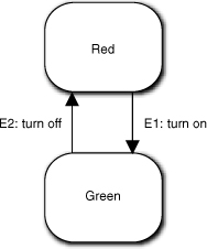
This is certainly plausible. We have cleverly converted the context’s view of On/Off into the indicator’s Red/Green view by the way we mapped the events to the transitions, and we have completely hidden both the actual colors and how they map to On/Off. Nice work, Grasshopper.
This sort of FSM might be reasonable in R-T/E where the software may have to write to the hardware to change the lamp color. This might involve some special formatting that is significantly different for red and green. Such formatting would represent different rules and policies. If so, that hardware control may be important enough to the problem (e.g., device driver software) to warrant thinking of it as a behavior with unique rules and policies.
Look for ways to recast behaviors as knowledge.
In general, though, we should look for ways to recast behaviors in terms of knowledge. That’s because manipulating data is usually easier, less complicated, and less error prone than organizing behaviors. Let’s suppose this On/Off indicator is an object in a higher-level subsystem where we aren’t worried about the details of the hardware. The question now becomes: Do we need an FSM to capture the constraints that Off always follows On and On always follows Off?
The odds are that the answer is no. The operative word is Indicator. This entity just shows us something that it knows, a status, which is basically knowledge that can simply take on different values. So, by its nature, an Indicator just tells us something we need to know. If we provided an FSM to capture every possible rule for setting all our knowledge values, we would complicate our model and end up with something like the Keyboard with an event for every key value.
But what if this object is a surrogate for a hardware device driver that needs to have hardware registers written whenever the status changes? And what if those writes are quite different for each state? Then aren’t those writes behaviors that implement unique rules and policies of hardware control? The answer is a definite maybe. Complex hardware writes might be a necessary condition for using an FSM, but they are not necessarily a sufficient justification.
We can think of any hardware register write as setting a knowledge attribute where the register itself holds the knowledge written.10 In addition, hardware reads and writes are usually very low-level activities compared to the level of abstraction where we might think about some entity being On or Off, so those writes probably don’t affect flow of control in the overall solution where the Indicator status is important. Therefore, they don’t directly represent unique business rules and policies that are necessary to resolve the subsystem subject matter where the On/Off indicator is abstracted.
That reasoning strongly suggests a simple knowledge-based abstraction. But the critical thing we need to think about is the sequencing of On and Off status. Who sets the status? Whoever that is needs to understand the sequencing. That is, they need to understand when the Indicator should be On and when it should be Off. If correct sequencing is important to the problem solution (e.g., the requirements say it would be an error to try to set the Indicator On if it was already On), then we need to be concerned about cohesion and whether the client needs to understand that sequencing rule or the Indicator.
Again, in this simple example it is likely that whoever sets the Indicator already has some notion of On and Off in its own context or the status is implicit in some system user’s actions (e.g., pressing the Power button). So it seems reasonable that Indicator is just a dumb data holder to keep track of what someone else is doing. In addition, there are tricks we can use to limit what the client needs to know, such as providing a change message that just toggles whatever status is currently there. That removes the need for the client to know exactly what the status is; it just needs to know that something changed, and Indicator needs to know about that.
OK, now let’s take the example a step further and do a Traffic Light. The Traffic Light has three colors, red, yellow, and green, that are cycled in a particular order for particular durations. (To keep things simple for the moment, let’s assume we have a different Traffic Light object for each direction.) We only have one color attribute. Do we still want to abstract the Traffic Light purely in terms of knowledge?
To decide that, we need a vision for collaboration. It is hard to imagine a context that does not involve timers here because the light cycles have fixed duration. Then the change is triggered by the timer’s time-out event, which is really convenient when we are using an asynchronous behavior collaboration model. So the questions are: Who triggers the Timer, and who catches the timer event?
Imagine this Traffic Light object is in an automated system where the traffic lights have fixed timing. In this case it makes sense for the overall system to initialize Traffic Light to a known state at start-up and then kick off an infinite loop of interactions between Traffic Light and Timer. That is, Traffic Light would understand the cycle. Traffic Light would start the Timer each time it changed to a new color using the appropriate duration for the new color. Traffic Light would switch to the proper next color when it got the Timer’s durationCompleted event. Thus Traffic Light and Timer perform an endless collaborative dance around the G → Y → R → G cycle. Since durations are likely to be different for each color, an FSM makes a great deal of sense here because of the nature of the collaborations between Traffic Light and Timer.
In contrast, suppose the system was a very sophisticated traffic management application for an urban area that adjusted cycle times on the fly based on actual traffic conditions detected by various sensors. In this scenario it is quite likely that some other entity is charged with monitoring sensors, analyzing data, and adjusting individual traffic light cycles (in fact, probably a whole subsystem!). In that context, what role would a single Traffic Light object have? Probably not a very big one. All the traffic flow decisions would probably be made elsewhere, and Traffic Light would just be, at most, a hardware surrogate or, at the least, a dumb data holder for the current light status. In this situation we are back to a knowledge-based object like On/Off indicator.
But maybe not. Suppose our traffic manager analysis only wants to deal with changing the traffic flow. It might think in terms of startFlow and StopFlow. Now when Traffic Light receives the stopFlow message, it would have to switch to Yellow and start the Timer for a fixed time, then switch to Red. But processing the startFlow message just switches from Red to Green. Now we are back to a collaborative cycle to be managed between Traffic Light and Timer. In addition, Traffic Light is enforcing nontrivial rules about processing a change in colors. So we again need an FSM; it is just a different one from that needed for the fixed-durations scenario above.
Hopefully you have come away from this discussion with these important insights.
• We can trade knowledge for FSMs, and vice versa, when representing the problem space.
• Even seemingly very simple entities can raise complex design issues because all the abstractions must play together in the design.
• Deciding between knowledge versus FSMs is dictated by the problem itself since the decision is fundamentally one of abstracting the problem space.
• Deciding between knowledge and FSMs is often critically dependent on the big picture of how objects will collaborate.
• We should look first for knowledge-based solutions.
• When sequencing of behavior is critical to the solution, we usually need an FSM.
Managing Sequences
Most of this book so far has railed against thinking about solutions in terms of sequences of operations. This was in the context of developing the static framework of the application. Now we are dealing with dynamics, and we can’t avoid dealing with sequences of operations because they are defined by the requirements. However, we can be disciplined about what sequences we think about and how we think about them in the dynamic description.
State machines capture constraints defined explicitly by functional requirements or implicitly in the way the problem domain works.
When identifying states and transitions, we identify operations where the requirements or a domain model explicitly indicate that one operation always precedes another. Such requirements are explicit constraints on the sequencing of behaviors in the overall solution. If the behaviors happen to be responsibilities of the same object, then we want to think about using an FSM to describe those sequencing constraints.
It is in our interest to capture as many of those constraints as we can in transitions. Doing so enforces the constraint in static structure, which minimizes the amount of dynamic description we need to enforce the constraint (i.e., the selections and condition testing to make sure it is the right time to invoke the behavior). As it happens, FSMs are ideally suited to this, because once the transitions are defined we need only ensure that triggering events are generated in the right place, and we have DbC to ensure that. This is a much less verbose and less error-prone way to ensure the sequencing constraints are properly managed.11
Step 1. Identify responsibilities with sequencing that are explicitly constrained in requirements.
The first step in developing an object life cycle is to identify the behaviors relevant to requirements’ sequencing constraints. Sometimes doing so will result in groups of small responsibilities where it is the sequencing of the groups that is constrained by requirements, not the individual responsibilities. Recall that an FSM state is a condition whereby a unique set of rules and policies apply. We will group those small responsibilities into a single state action to be such a set.
Whoa! Doesn’t such merging into a single state action fly in the face of logical indivisibility of behavior responsibilities? The answer is that we also have flexibility in defining the level of abstraction of logical indivisibility. In effect, we are using the requirements constraint on a group of individual responsibilities to determine the correct level of abstraction for collaboration. In other words, we start our design at a low level of abstraction for logical indivisibility because it is easier to evaluate the sequencing constraints if the individual responsibilities are narrowly defined. But the problem constraints drive the actual level of abstraction where we end up because they define a degree of commonality among the detailed behaviors.
Note that this is inherently an iterative process. As we refine our view of logical indivisibility, that will be fed back in terms of more abstract behavior responsibilities identified in the Class model, and it will also refine our overall vision of the solution when we define other object FSMs. It is also the reason that we don’t try to define detailed collaborations before we define the FSMs. We need the collaborations to be done at the right level of abstraction, and this step—where we let the requirements drive the level of abstraction—is important in ensuring that. If we design interacting FSMs with detailed messages based on our original view of logical indivisibility, we are likely to create FSMs that are too complicated.
A classic example of this is a common problem cited by those who believe FSMs are ill-suited for certain problems. The problem is to represent keyboard entry of words into GUI text boxes. The critics postulate an FSM based upon a unique event for each key on the keyboard. This requires a set of transitions through states that migrates through every possible incremental combination of valid characters. A partial example is shown in Figure 15-6(a) where each state is a unique concatenation of a particular sequence of characters. Clearly, such an FSM is just not practical for more than a few valid and very short words.
Figure 15-6. Example of a really bad state machine and a much better way to model the semantics
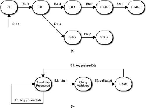
The FSM in Figure 15-6(b) is superior because the level of abstraction of the sequencing constraints has been raised. Now all keystrokes except one from the hardware or OS look exactly the same. Nonetheless, the FSM honors the very basic keystroke sequencing constraint that a valid word be formed. We just don’t do the word validation in the object that processes raw hardware keystrokes. That is the real problem with the critics’ example: It hypothesizes poor object semantics and separation of concerns.
It would simply never occur to an experienced OOA developer to even think about an FSM like Figure 15-6(a) because the object semantics would not have that word validation responsibility when the Class model was done. The semantics of a Keyboard abstraction is polling the hardware, converting hardware codes to ASCII, applying modifiers like Shift being pressed, and (possibly) concatenating keystroke codes in a buffer. That is at a much lower level of abstraction than thinking about whether valid words are formed. (In fact, the word validation might not even be in the same subsystem as the hardware control represented by the notion of a Keyboard! The idea of a Keyboard might only be relevant to a specialized service that the UI invokes.)
Aside from encapsulating the right semantics, Figure 15-6(b) is interesting in the way in which abstraction is used to capture the sequencing constraints. Note that all keystrokes except Return are treated as if they were equivalent. Raising the level of abstraction of the keystroke messages is critical to eliminating the combinatorial problems of the first example. When we raise the level of abstraction, the individual letter values are relegated to parametric data values in the event data packet. Essentially we have reformulated the sequencing constraint to be consistent with the notion of external validation. That is, the Keystroke Processed state consolidates the set of basic processing steps.
- Check for temporary modifier keys. These are Shift, Control, Alt, and so on that modify the ASCII codes for all subsequent keystrokes until they are released. Record the state and exit.
- Check for special keys. These are Caps Lock, and so on that modify the ASCII codes until they are pressed and released again (i.e., they are treated as individual keystrokes but they affect the way the keyboard interprets other keystrokes in terms of ASCII codes). Record the state and exit.
- Encode the proper ASCII code for the hardware keystroke value given the current effects of modifier and special keys.
- Concatenate the ASCII keystroke value into a temporary string buffer.
This is a good example of a number of logically indivisible operations that can be combined because they apply to every keystroke except Return, and these operations always have to be done before other operations, like validating the word in the string buffer. In fact, we could abstract all four of these operations into the more general notion of updating the state of the Keyboard.
Note the spin this model places on validation. We only validate the string in the buffer when the user has indicated the string is done (i.e., hitting the Return key). That makes the Return keystroke special, and it draws a line in the sand that divides the activities for processing all other keystrokes from the activities of validating the word and resetting for the next entry. Thus we can summarize the new overall processing constraint at the new level of abstraction as follows:
- Collect the text box string one character at a time. This action includes the four behaviors above.
- Validate the string.
- Reset the text box after validation processing.
You will note that this is exactly the life cycle that the second example shows. Quelle surprise!
Note that this segues back to the point made previously: that we should look for ways to abstract behavior in terms of knowledge. Encoding modifiers and special keystrokes as state variables is a very elegant way to simplify the behavior of the keyboard and, in this case, it is one way to eliminate the critics’ combinatorial problem. As such, the example is a good demonstration of how we marry knowledge and behavior to provide a simple solution for a superficially complex problem.
Now suppose the Keyboard did not queue up a buffer of keystrokes; instead, it simply forms the ASCII code and sends it to someone else. Now we have an entirely different situation where the last two steps are no longer relevant. What does this say? Obviously we have only one state, so there are no sequencing constraints to capture, which tells us that our Keyboard does not need an FSM. We could view processing the hardware keystrokes as simply knowledge setters for attributes like ASCIICode, and the ASCII code would be forwarded as a simple knowledge attribute value.12 So in this case the entire object becomes a simple data holder or even an attribute in another object.
It is worth reviewing the essential insights that led to the second solution rather than the critics’ because we need to design the right FSM while we are at it. First and foremost was separation of concerns. It was critical that our Keyboard object should not be distracted by the rules and policies for validating words; it should stick to the narrower focus of converting hardware register values to ASCII codes. That is logical indivisibility and cohesion in action at the object level. Another important insight was abstracting the invariants of text box string processing. Our FSM was focused on the stipulated problem in hand (i.e., termination via Return). If we had been modeling the Keyboard for a word processor, we might have had a suite of delimiter characters that would indicate the end of a word.13
However, though the transitions we ended up with were tailored to the problem in hand, the life cycle states were intrinsic once we properly abstracted what the object responsibilities were. To put it another way, the states represented an extraction of invariants from the problem space at a higher level of abstraction than in the critics’ solution. A key insight in this solution is the way the sequencing constraints are abstracted. That is, in turn, reflected in the states, the transitions, and the nature of the events. Throughout this book, abstraction has been promoted as the defining element of OO development, and this is just one more example of how ubiquitous it is in OOA/D. This all segues into . . .
Step 2. Isolate the behaviors in states and enforce the sequencing constraints in transitions.
This sounds a lot more cookbook than it actually is. Hopefully, the reasoning in the previous example illustrates the sorts of issues and techniques that are relevant. Probably the most important element of the proper mindset is the notion that OO FSMs are abstractions, and both the object responsibilities and the FSM need to be at the right level of abstraction. That may require some iteration and creativity to get right. Fortunately, though, practice makes perfect, and it doesn’t take all that much learning curve to get good at it.
Self-Directed Events
The topic of managing sequences would not be complete without a discussion of one of the most controversial issues in FSM design. It is possible for an FSM action to generate an event to its own FSM that causes a transition. If you recall, we even have a special rule for prioritizing such self-directed events. Unfortunately, self-directed events tend to be badly overused, especially by novices. In fact, there is a school of FSM design that argues we should never use self-directed events.
The reason is rooted in the FSA notion that transitions are triggered externally to the state machine. The FSA state conditions reflect conditions in the environment of the FSA, and the FSA simply organizes them in a disciplined model, thus how we decide the state should change is not the FSA’s concern. However, we have bent the FSA rules before to provide OO FSMs, so this theoretical issue is not completely compelling.
A much more practical problem has to do with the notion of a sequence of operations itself in a software context. In Figure 15-7, assume the actions for State1 and State2 each result in a set of machine instructions and imagine the sequence of instructions that the CPU “sees.”
Figure 15-7. Context for self-directed events

The point here is that if the State1 action generates the E1 event, then there is no point to having the two states. There is no flow of control circumstance where the State2 action’s instructions do not seamlessly follow the State1 action’s instructions. In effect, all we have done is artificially subdivide an otherwise monolithic Turing sequence of operations. To put it more bluntly, all we are doing is using FSM state actions to organize our behaviors into classical procedural units. Anything that even hints at procedural organization is going the have the reviewers lighting the kindling under our feet.
Now suppose E1 is generated externally. The CPU may see the full sequence as above, but that will be serendipity because we don’t know when that event will be issued. Within the logic of our overall solution, a ton of instructions might be executed between the executions of the State1 and State2 actions.
Use synchronous services to organize complex monolithic sequences, not FSM states.
The mechanism MBD uses for connecting the flow of control dots is interacting FSMs. Don’t dilute that by using states and transitions for other purposes. The benefit of keeping the FSMs pristine will not become apparent until you are debugging or doing maintenance. At that point we need to be able to count on a transition representing a fundamental element of flow of control without having to rummage around in the action details. A lot of debugging and change analysis is done just by looking at boxes and arrows without the action details.
Having argued strongly that self-directed events are usually symptomatic of poorly formed FSMs, how is that reconciled with the opening of this topic where it was hinted that some self-directed events are justified? In MBD we do sometimes employ self-directed events, but we are very careful about when we do so. The reason is that in object FSMs we have conditions that depend on the timely update of state variables (knowledge attributes). There are situations where the handshaking necessary to ensure data integrity would require additional states and transitions (and sometimes additional objects!) that might distract from the overall purpose of the interacting FSMs.
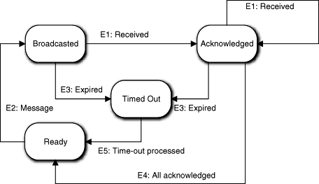
Figure 15-8 represents an object with the role of broadcasting a message to multiple recipients, collecting acknowledgments that the recipients received it, and determining whether some recipients did not acknowledge the message within some elapsed time after the broadcast. The Broadcasted action saves the count of messages sent and initializes a Timer object that returns the E3:expired event. The Acknowledged action counts the acknowledgments and, if it matches the number sent, it shuts down the Timer. The key rule that must be enforced is that the object cannot start another broadcast until the current one has completed, either by receiving all the acknowledgments or experiencing a time-out. That is captured by the fact that E2:message is only valid for the Ready → Broadcasted transition. One problem is that the E4: All acknowledged event is self-directed.
Figure 15-8. A state machine that broadcasts messages must wait until all messages are acknowledged or a time-out occurs before broadcasting another message.
The tricky part here is getting to the Ready state when the recipients have acknowledged. We could delegate the responsibility of counting acknowledgments to another object that exists purely to count the entries. The E1:received message would go to that object and it would do the counting. When the counts matched, it would send the E4:all_acknowledged event back to the object in hand.
That’s valid, and the conservative school of FSM design would argue that it is more robust. It may be somewhat more robust, but it is probably overkill for several reasons in this situation. First, we have to create an artificial object that may have no counterpart in the problem space just to get around a self-directed event. Second, that object needs its own FSM to be designed. Third, it needs to be initialized by the Broadcasted action with the count to check. Fourth, the interactions may get complicated when there is a time-out (e.g., what do we do with the E1:Received events if the allowed time has already elapsed?). Fifth, that other object might only have one state. Finally, perhaps most important of all, providing such infrastructure just distracts from the core problem of broadcasting messages and collecting responses. So in a case like this, opting for the self-directed E4:all_acknowledged event to keep things simple will usually be the best choice.
Try to justify self-directed events in terms of resolving both the FSM and state variable (knowledge attribute) views of “state.”
Note that this is a clear case where persistent state variables across FSM state actions are relevant. The count needed is accumulated across transitions. Probably more important, that count seems to logically belong to the object doing the broadcasting. Thus the self-directed event is really just combining two views of object “state,” which provides some additional rationalization.
Another problem in the example FSM lies in getting to the Ready state after a time-out has been processed. Here, no obvious state variable update is involved, which should make us rather suspicious because we have no rationalization about marrying different views of object state. In fact, someone reviewing the example state machine would probably be bringing out the matches and kindling. That’s because there is an obvious and simple way to avoid the self-directed event from Timed Out to Ready.
To see that, think about the basic purpose of the Ready state. It enables us to enforce the constraint that the object is not already busy processing a message (i.e., the condition is that the processing of any previous message is done). This provides an anchor for the E2:message transition that captures the sequencing rule. However, after processing the time-out, is the object any less done processing the current message than if all of the recipients have acknowledged receipt? No. When the object is in the Time Out state, it is just as unoccupied as when it is in the Ready state. So instead of the Timed Out to Ready transition with the E5:time_out_processed being generated, we should just have a transition from Timed Out to Broadcasted triggered by the E2:message transition. The example is an interesting contrast of reasonable and bad practice.
Handshaking
Since we are employing an asynchronous model for behavior communications, we have to live with handshaking as a Way of Life. When two objects, both with embedded sequencing constraints, need to collaborate, we need a mechanism for keeping the collaborations synchronized. That is, we need to ensure that the receiver is in the right state to accept the event that the other object sends. Alas, this is complicated by the fact that an important assumption of asynchronous communications is that there can be an arbitrary delay between when an event is generated and when it is consumed. Thus, in theory, it is possible to generate event E2 after E1 but have E1 consumed before E2. In fact, this is rather common in distributed processing.
However, in the OOA/D we make a couple of assumptions, which we’ve already talked about, that greatly simplify these problems. The important assumption is that there is a single event queue for all events processed in the subsystem. The second assumption is that only one event is popped at a time, and its action completes before popping the next event from the queue. The third assumption is that the event queue is FIFO; events are popped in the order in which they were placed on the queue.14
These assumptions conspire to ensure that events within the subsystem are consumed in the same order that they were placed on the event queue. Fortunately, these assumptions are fairly easy to enforce in the implementation even in distributed and/ or concurrent environments. But transformation is a different trade union so we won’t go into that here.
The basic problem comes down to making sure the events go on the event queue in the right order. That’s not always easy when there are long, parallel chains of processing. It gets more complicated when the knowledge needed by an action at the end of one of those chains is updated somewhere in the middle of another chain. An example is shown in Figure 15-9. The figure is just a flow chart that represents the algorithmic sequence in the solution if (A,B,C} and (X,Y,Z} were readily recognized individual sequences in the problem space.
Figure 15-9. Overall solution sequence context for executing multiple state actions

The S action kicks off both sub-processes and the D action must wait until both C and Z execute, but it doesn’t care which one completes first. This might arise if B needs data from A, C needs data from B, Y needs data from X, Z needs data from Y, and D needs data from both C and Z. Since D is indifferent to which sub-process finishes first, we could make an arbitrary design decision to serialize the sub-processes, as in Figure 15-10.
One of the problems with simple flow charting was that it was easy to miss more subtle dependencies. Suppose that Z also depends on data updated by B. If these sub-processes were in different parts of the application, that might not be so obvious, especially if the requirements call out the sub-processes individually that might result in some myopia about what processing was important. Assuming our due diligence with DbC uncovered this dependency, then connecting the dots in Figure 15-10 was wrong. So how do we correct it? One way is to reverse the order of the serialization so that S triggers A, C triggers X, and Z triggers D, shown in Figure 15-11.
Figure 15-10. Serialized version of Figure 15-9
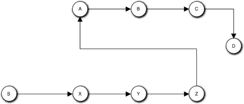
Figure 15-11. Revised serialization to ensure data prepared by B is available to Z
OK, so far so good. But now let’s assume that {A, B, C} are behaviors of one object while {X, Y, Z} are behaviors of another object. Now we have four self-directed events that should raise a warning flag. At this point it may help to make things a bit less abstract. Let’s assume these two objects are different flavors of test instruments, say, an Ammeter and a Voltmeter. Now the three behaviors of each object might represent different implementations of {setup, initiate, and fetch}. Finally, assume the requirements say that our application must be compatible with the VXI standard, which decrees that {setup, initiate, fetch} must be independently accessible so we can’t coalesce them as we did when initially talking about self-directed events. Are we now forced to use self-directed events?
No. What we need to do is step back and look at what the real sequencing constraints are.
• A → B, B → C
• X → Y, Y → Z
• C → D, Z → D
• B → Z
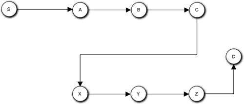
These are the only constraints that we must honor in the flow of control. As long as each individual dependency is handled correctly, we can order the processing of all the actions in a wide variety of ways, of which Figure 15-12 is just one example.
Figure 15-12. Sequence diagram for synchronizing the sequence in Figure 15-11
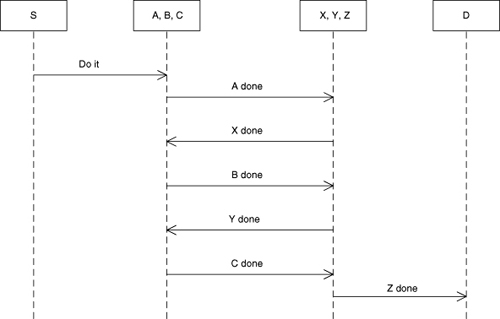
Now Do it from S triggers A, A done triggers X, X done triggers B, B done triggers Y, Y done triggers C, C done triggers Z, and Z done triggers D. You can easily verify in the Sequence diagram that all of the actual constraints have been honored. Given our more realistic test instrument interpretation, this is actually a better picture of what is really going on in synchronizing the instruments.
The real benefit of eliminating the self-directed events this way, though, is that maintenace will be easier to do. We would not want to coalesce the actions even if the VXI standard weren’t an issue. For our simple example, we could manage the sequences in a monolithic fashion as in Figure 15-11, but the self-directed events would encourage us to combine the actions (which would be harmless for this example). If you have any familiarity with rack-and-stack hardware test systems, it should be clear that future requirements might require the actions to be separated.15 So, when the requirements change you would have to un-combine them and rearrange the messaging. By avoiding the self-directed events we get to the right place in the original development, so all we have to do during maintenance is rearrange the events. (As a bonus, the Sequence diagram makes it clear that the sequencing of messages is not tied to the sub-processes.)
A useful tool for getting a handle on handshaking situations is the UML Activity diagram. We can create a rough, throwaway AD for the relevant use cases to show “touch points” in the uses cases among multiple objects. That can be useful in figuring out how to deal with the synchronization.
Some Examples
As we’ve already indicated, for novices there tends to be a bit of magic in recognizing life cycles in problem space entities that we can abstract into object FSMs. In addition, the steps indicated and the issues raised might sound fine, but they are a tad general for easy application in real software projects. Unfortunately, there is no cookbook approach to the learning curve. So the best we can do now is provide a few examples to demonstrate how we should think about looking for life cycles.
Garage Door Opener
This is a classic starter project for novices because it is quite simple, but it demonstrates a number of interesting features. Let’s assume we have identified the following objects as relevant: Clicker, which triggers opening or closing the door (ignore registration and whatnot here); Door, for which we are controlling opening and closing; Electric Eye, which detects obstacles to closing; Position Sensor, which determines if the door is fully open or fully closed; and Controller, which talks to the hardware elements. The question is: Does Door have a life cycle?
If we think about what a garage door controller actually does, it isn’t a whole lot. If the Door is closed and the Clicker is clicked, the hardware is told to open the door. If the Door is open and the Clicker is clicked, the hardware is told to close it. If the Door is closing and an obstacle is detected, the hardware is told to open the Door. When the Position Sensor indicates the Door is fully opened or closed, the hardware is told to stop moving it. (This last is probably done directly in the hardware, but this is just an example.)
If you have a few years of non-OO development under your belt, the answer will be obvious. There is only one object that actually does anything and that is the Controller. So the Door has no life cycle. Of course, that answer is dead wrong or we wouldn’t have chosen this example. Just because an object has an “–er” at the end does not mean it coordinates everyone else. In fact, such a name would immediately make an OO reviewer suspicious because it screams of being a high-level node in a functional decomposition tree that coordinates the machinations of minions at lower levels in the tree.
Look at the descriptions of what the objects are. Which one is moving (i.e., changing state)? It appears in every sentence describing an activity. More telling, it appears in those sentences that describe conditions (e.g., “If the Door is open...”). If there is one object here that is active, it is the Door. In fact, it is the only object that really needs to do anything; the others are really just surrogates for the hardware.16
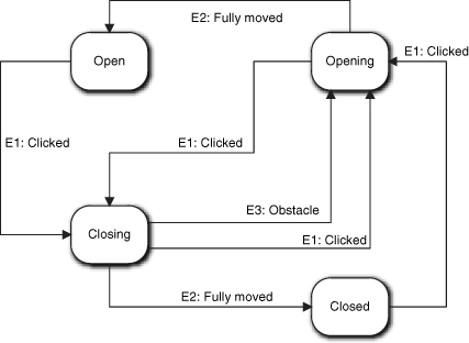
So what kind of life cycle does Door have? Obviously there should be states for Open and Closed. Is that it? No. The problem is that it takes awhile to actually get from one state to the other and things can happen in that interval, like the Clicker was clicked again or the Electric Eye detected a beaver standing in the doorway. To properly capture the constraints implicit in the problem description as transitions, we need more states. In particular, we need Opening and Closing.
Note that in Figure 15-13 we have four states and six transitions but only three events. (The actual number of events will depend on the specific hardware.) That essentially means we are capturing a lot of rules in the static FSM structure—more than we probably thought there were when reading the problem statement. Note that this FSM is quite intuitive.
Figure 15-13. State machine for controlling a garage door
Automated Home Kitchen
Let’s assume we need to write the controller for an automated home kitchen that will prepare a complete meal unattended. One of the many objects will be an Oven that is used to cook the meal. Given that this is one element of an automated process, does Oven have a life cycle?
We can make a case that it is a dumb data holder. It just records the start time, temperature, and duration of the cooking cycle for some other process that emulates the cook. However, that phrase, “process that emulates the cook,” should set off alarms. Our software is replacing the cook with an automated system, thus the software will be doing things the human cook would have done. We could create a Cook object to play that role, but we would essentially be creating a god object that controlled all the behaviors.
In OO development, the way we avoid this is through anthropomorphization. We allocate the actions that a human cook would have done to inanimate entities in the problem space, such as an Oven. That allocation enables us to separate concerns when managing complexity. So our Oven is likely to have behavior responsibilities that are a small subset of what the human cook would normally do. What sorts of behaviors are those likely to be? The Oven needs to be initialized by setting temperature, and so forth. It also needs to be preheated. A human cook would have to perform a set of discrete actions on the Oven before actually putting the roadkill in for cooking, and those are constrained to a particular sequence. That, in turn, suggests states like Inactive, Temperature Set, Preheated, and Cooking.
Another way to look at this is to think about how the notion of Oven fits into the overall notion of Automated Home Kitchen. The objects that we abstract for the Automated Home Kitchen will have to collaborate with one another, which implies that there are some rules about sequencing activities. Thus Robotic Handler cannot put the roadkill in the Oven unless the Oven door is open. In addition, the Oven will have to interact with objects like a Timer. In the overall scheme of automatically preparing a meal, there will be a whole lot of recipe-like operations, many of which will be constrained to be in a specific sequence. This is particularly true for automation, where we need to be quite explicit about trivial things like opening doors. So our Oven may also have states like Door Open and Door Closed to support the necessary collaborations with other objects.
We want to capture as many of those sequencing rules as we can statically in FSM transitions. With this minimal description we can’t say for sure what the states and transitions for Oven are, or even if it will have a life cycle in the final model. However, the discussion should make it clear that there could be one, that it might be fairly complicated, and that we need to at least evaluate it.
Air Traffic Control System
In an ATC there is a notion of the position of an aircraft. That notion combines radar data, altimeter data, and error envelopes. (Actually, several data from different types of radar and from the aircraft itself are combined in the notion.) There is also complex analysis to associate raw radar data with a particular aircraft.17 Even more complicated analysis is necessary to determine error envelopes in three dimensions for collision avoidance processing. As a result, the Position data that is ultimately displayed on the controller’s console is the end result of complex processing from multiple subsystems. The question is: Does the Position have a life cycle?
Probably not. The keyword that recurs in the description is data. The processing necessary to construct and refine a Position object may be quite complex, but that will most likely be done by a combination of other objects. However, this was a bit of a trick question. There is another view of Position that may be relevant. Aside from the data itself and the processing to provide it, there is another set of sequencing constraints around the notion Position. Those constraints are related to the processing necessary to construct a Position.
This processing is done in a specific sequence from the time raw radar data is acquired until the time the Position is displayed for the controller. We must correlate raw positions from different radars, then associate the collection with an aircraft transponder, then include altimeter data, then adjust the altimeter data for weather conditions in the aircraft’s location, and so on. And that is just to get the data. Additional analysis is required for things like error envelopes, flight path tracking, and, finally, symbolic display on the controller’s console. One way to capture those sequencing constraints is via transitions in a state machine that reflect the state of the Position in the processing sequence. That state machine would probably reside in some other object (e.g., Position Constructor) because Position itself has quite a bit of knowledge already, but the notion of a construction life cycle for Position is still valid.
There are two points to this example. The first is that an FSM is there in the problem space to abstract as a life cycle, and we need to think about it. After due diligence we may decide that particular abstraction is unnecessary to the overall ATC problem solution, but we still need to make that a deliberate design decision. In other words, we are deciding whether we need the life cycle to solve the problem in hand, not whether one exists.
The second and more important point is that life cycles are abstractions just like everything else in OO development, meaning that we need to be prepared to view the problem space in different ways. We can’t simply dismiss Position as a data holder; we need to look at the big picture from different angles. In reality, once you start looking for life cycles you realize that there is almost always some bizarre problem context where virtually any pedestrian inanimate object has a conceptual life cycle. The following example is a case in point.
Rock
This is your garden variety stone outcrop, as in a road cut. For most people there is simply not much to it—it’s just that hard, dull grey, bluish or reddish stony thing. To the trained eye of a field geologist, though, the outcrop is a wealth of information about the history of the rock. To a mineralogist, the rock is actually quite complex, being composed of several different mineral crystals or even other rocks. Similarly, to a petrographer who studies the microscopic structure of the rock, it has exotic chemistry and there are many clues about its evolution. On closer examination, a paleontologist may find fossils in the rock that shed light on its age and evolution. Still, that just indicates complexity that requires special training to recognize, and it is all just data, right?
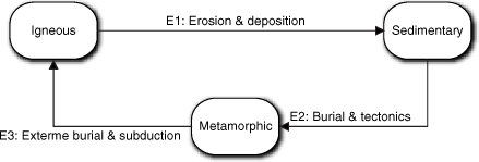
Au contraire. It depends upon your perspective on viewing rocks. To demonstrate that, though, we need to digress a moment to Geology 101. In geology there is a conceptual model quaintly known as the Rock Cycle. All rock we see today originally cooled from a liquid form called magma to form igneous rock, which basically means crystalline. (The lava that flows out of volcanoes is a classic example of igneous rock formation.) Once it solidifies at the surface it is exposed to erosion by wind, water, temperature changes, and other mechanisms. Erosion breaks down the rock into tiny fragments that are carried away and deposited somewhere else as sediment. Erosion can even modify the rock chemically. These fragments are eventually buried, so they are subjected to increased heat and pressure, which causes them to consolidate into sedimentary rock. Depending upon depth of burial, time of burial, temperature, and pressure, both igneous and sedimentary rocks can be further modified chemically and physically to form metamorphic rock. In extreme cases, conditions can be so harsh that metamorphic rock completely melts to form magma. That magma may subsequently cool, repeating the cycle by forming igneous rock. All rocks we see today on the Earth’s surface have been through this Rock Cycle, shown in Figure 15-14, several times.
Figure 15-14. The legendary Rock Cycle
Now suppose you are tasked with constructing software that simulates the life of a portion of a continent for a mining company. The mining company is keenly interested in this sort of thing because different types of rocks have different minerals. In addition, we have found all the easy resources lying around on the surface, so they have to predict what is under the surface. Since drilling and mining to “prove” resources are very expensive, they want to do it in areas with the highest probability of success. By simulating a mountain building episode (aka orogenic cycle, yet another life cycle of interest), they may be able to predict where the most beneficial rocks have formed. Now the Rock Cycle becomes critically important to the simulation because they need to identify where the clumps of igneous, sedimentary, and metamorphic rocks are today as a result of continental drift millions, or even hundreds of millions, of years ago.
Conceptual processes have sequential constraints in the same way that solution operations have sequential constraints.
There are multiple points to make here. One is that no matter how inert an entity might seem, there is usually some perspective where it has a life cycle, however arcane and special the perspective may be. In this case that perspective is historical and only of interest to a unique academic discipline. Next, it is not the rock itself that does something today; it is the way it evolved that provides the life cycle. That segues to the third point: The problem context itself can determine life cycles, in much the same way that anthropomorphizing human activities onto inanimate objects provides life cycles. That is, we map an evolutionary process onto the rock instead of human activities. The last point, to quote a famous pool player, is that, “I was jus’ showin’ off.”18