
Chapter 17. Developing State Models
The proof of the pudding is in the eating, but not if the eater is a poor judge of pudding.
—Anonymous epigram
Alas, anyone can whip together a state machine. When the whippers are incompetent one will get bad state machines, as the Keyboard example in the Part III road map indicated. The main ingredient of state machine design competence is the right mindset, as discussed in the previous chapter. In this chapter we will discuss a more detailed approach to designing state machines that will help avoid foot-shooting when combined with the right mindset.
Most of the work in state machine design is actually done when one allocates behavior responsibilities to the class. If one religiously applied good OO problem space abstraction in identifying classes and responsibilities, much of the battle is already won. All you have to do is identify sequencing constraints among those responsibilities and you will have the core structure of the state machine.
Designing State Machines
The best way to think of an object state machine in an OO context is in terms of an intrinsic life cycle.1 That life cycle consists of a set of states of being and constraints on migrating through those states. The states of being are determined by the intrinsic nature of the underlying problem space entity, while the constraints are determined by the overall solution context.
This is arguably the most important step in designing state machines. The idea here is to figure out what behavior the state machine manages and, more importantly, at what level of abstraction that management occurs. If you did a good job of documenting what your objects and responsibilities are, then most of this will be done already. Then your only remaining concern is expressing collaborations in terms of that level of abstraction.
This is all rather esoteric, and it probably won’t mean much until we get to some examples later in the chapter. The main point here is to regard the state machine as a control structure for the object-in-hand’s role in the overall solution. We want the overall state machine structure to be consistent with the subsystem’s level of abstraction and the object’s mission within the subsystem subject matter. From that perspective, the specific behavior responsibilities we have identified for the object are black boxes that will be encapsulated within state machine actions. Thus we are only interested in how the state machine connects up those black boxes, not what those black boxes actually do in the solution.
For example, consider changing a simple Traffic Light’s color. There are several possible views of collaboration corresponding to different levels of abstraction of the collaborations, such as: setRed, where the determination of color is the client’s responsibility; toggle, where the color details are handled in the Traffic Light implementation; and haltTrafficFlow, which has nothing directly to do with Traffic Light’s color. The level of abstraction of those views will determine whether we need a state machine at all and, if so, what collaborations it may have (e.g., with a Timer for yellow to red). Thus for setRed, we can probably cast all of the Traffic Light’s responsibilities in terms of knowledge, but for haltTrafficFlow we will be capturing problem space rules about the red → yellow → green cycle that might better be captured in behavior responsibilities.
One of the most common mistakes in state machine design is to let the state machine design be driven by detailed behaviors. In fact, we will quite often combine multiple individual behavior responsibilities in a single state action.2 Alas, the author has seen state machines with literally dozens of states, most of which are connected by self-directed events. Each state action dutifully encapsulated a single logical behavior responsibility from requirements. The problem was that in the actual solution context the precondition for executing many of those behaviors was exactly the same, so the states merely represented algorithmic steps in a single basic behavior. Those behaviors with the same precondition should have been coalesced into a single action where the sequence would simply be the order of steps within the action. Doing so would have eliminated the self-directed events and reduced the overall state machine size to a handful of states.
Requirements line items do not map 1:1 to state actions.
This is because in the context of collaboration with external objects, the granularity of the collaboration may be much coarser than the granularity of the individual, logically indivisible behavior responsibilities within requirements. To put it another way, collaboration is about when those line items must be resolved. Logically, the collaboration context that determines when they must be resolved may be the same for several of them. We capture the when in transitions while we capture the what of individual steps in actions. Therefore, your first task in designing a state machine is to examine the level of abstraction of the collaborations to determine when things should happen.
Step 2: Identify the “hard” states.
The first cut at an object state machine should be done purely on the basis of identifying intrinsic states of being that are relevant to the problem in hand. The so-called “hard” states are those that represent concrete or physical states like {Open, Closed} for a garage door. These will usually be fairly obvious.3 This view of the life cycle forms the kernel view of the intrinsic entity nature. The so-called “soft” states like {Opening, Closing} probably won’t show up until you try to resolve the sequencing constraints.
Step 3: Allocate behavior responsibilities to state actions.
Start out with one responsibility per state action. Now we switch gears and think of the state not as a state of being, but as a condition that enables that set of rules and policies. For each state, we select the appropriate behavior responsibility that should prevail when the object is in that condition. It is important to keep this view abstract. A behavior responsibility may implement multiple individual rules and policies from requirements, but we only care about the overall responsibility (i.e., the set of rules and policies determines what the responsibility does, not the individual rules and policies within that set that determine how it does its thing). A common novice mistake is to start writing actions before the state machine structure is completed.
When all you have are “hard” states, the odds are you will have a couple of behavior responsibilities left over. For example, in the garage door example in Chapter 15, there are no special rules and policies for the Open and Closed states. All the action does is send a message to the Motor announcing that movement is completed (i.e., the condition has been achieved) so that it can turn itself off. This should be a big clue that there are some missing states because responding to the beaver in the doorway is something those states aren’t handling.
Step 4: Combine behavior responsibilities in state actions, if necessary.
When one considers collaborations, it may be necessary to combine the responsibilities that we so carefully made logically indivisible into a single state action. This is where we have to start keeping one eye on the overall problem solution context. When we combine responsibilities in an action, we raise the level of abstraction for logically indivisible so that it is consistent with the collaboration context—which we didn’t directly consider when defining the static structure. Thus responsibilities that were logically indivisible as individual entity properties may not be in the special circumstances of particular collaborations.
Of course, one needs to be careful when raising the level of abstraction. It is important to be quite sure that all the possible collaboration contexts always need all the combined responsibilities to prevail at the same time. This sounds more complicated than it really is. In practice it is a whole lot easier to coalesce fine-grained elements than it is to recognize the need to decompose coarse-grained elements. Perhaps more relevant, since our subsystem is quite narrowly defined from application partitioning, there probably are not going to be a whole lot of collaboration contexts to worry about. In addition, the level of abstraction that we defined for the subsystem helps a great deal in figuring out the level of abstraction of collaborations.
The rigorous acid test for whether rules and policies can be combined is DbC. If the preconditions for executing two responsibilities are exactly the same, then they can be combined. That’s because those preconditions will both match the same postcondition of an external object’s action, so the triggering condition always occurs at the same time in the solution. Typically one doesn’t need to think about it so formally, though. The fact that some set of rules and policies is the logical response to the same announcement will usually be pretty clear.
In fact, if one employs a rough Collaboration diagram to keep track of collaborations as one develops state machines, it will usually be obvious by inspection that a single collaboration will trigger multiple responsibilities when the responsibilities have been defined more finely than the collaborations. Therefore, it is strongly recommended that you use a white board Collaboration diagram to “rough out” collaborations.4
There are two reasons for adding states. The obvious one is that there are behavior responsibilities that have not been accounted for in the existing states. The less obvious one is to facilitate collaborations. These are sometimes known as “handshaking states” because in networking and R-T/E domains one often encounters communication and hardware protocols that require an exchange of synchronizing messages in a predefined sequence. This exchange is commonly known as handshaking, as I described in Chapter 15.
If one has behavior responsibilities that don’t seem to fit into the existing states, one needs to provide a home for them. Alas, one can’t simply add a box to the Statechart, assign the responsibilities to the action, and make up a random name for the state. Adding states is probably the activity in state machine design where a proper mindset is most important. The state needs a rationale to be added. The rationale requires the state to represent an intrinsic state of being of the underlying object and to map into a condition for executing the associated behavior. If the rationale cannot satisfy both these goals, it is time to revisit the allocation of responsibilities to the object and/or the expected collaborations.
Keep in mind that when adding states one is providing static structure as the framework on which the dynamic solution rests. For robust and maintainable software, that structure needs to be stable. One way to provide stability is to map the state to an invariant in the problem space, such as an intrinsic state of being. In doing so, though, we need to be selective about what invariant to map. That selection is driven by how the object collaborates with other objects within the specific problem solution. In other words, the selection must be consistent with the object’s collaborations.
One way that is manifested is through collecting behavior responsibilities into actions when there are multiple “left over” responsibilities. It may not be possible to put them all into a single state because of the constraints of collaboration. That is, the preconditions for executing some of the responsibilities may be different than for others. Those different preconditions essentially represent different collaboration contexts. In that situation the responsibilities need to be allocated to multiple new states. (In a sense this is a form of delegation within the state machine.)
Another way collaborations come into play is through handshaking. Typically, handshaking requires additional states. Quite often those states will not actually do anything. That is, there will be no associated behavior responsibility for the state action to execute. Such states are characterized by simply generating an event in the action to announce that the state condition had been achieved. For state machine novices this leads to an obvious question: If the state has no prevailing rules and policies, why do we need it?
The answer lies in the handshaking we talked about in Chapter 15, and we need to amplify on that discussion a bit for this context. Basically, handshaking introduces the notion of a handshaking protocol that essentially allows the receiver to tell the sender when it is safe to put an event on the event queue. Thus, the sender must wait until it is told it is safe to execute the problem action. There are lots of variations on the protocol, but the essential elements are a communication like the following:
Sender to Receiver: I just did X.
Sender to Receiver: I just did Y.
Receiver (internally): Now I get to do my thing because X and Y are both complete.
The premise here is that the Receiver needs to do something that depends upon both X and Y being completed. But the Receiver cannot depend on the Sender doing them in any particular order. More important, from the Sender’s perspective they are unrelated activities. That is, X and Y will be done in different actions associated with different states. Recall that the rules of FSA preclude a state knowing whether another state has been executed. Therefore, it cannot be the Sender’s responsibility to send an “X AND Y are done” message. The Receiver must somehow wait until both are done because that is the precondition for doing its thing. Typically that “waiting” will require an additional state.
In Figure 17-1 we solve that problem by allowing either E1 or E2 to transition to Waiting, whichever comes first. Then when the other event arrives it will trigger a transition to Did Something Else. In this case the Waiting state action does nothing at all.
Figure 17-1. FSM that must wait for two events before proceeding
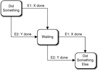
Extra credit question: What happens if two E1 or two E2 events arrive?
That would certainly be a problem, Grasshopper—if it could happen. It would not happen if the Sender’s life cycle was constrained so that the actions doing X and Y always alternated, which is quite common because most life cycles form a true graph cycle. If you recall, we also have a rule saying that events from the same sender to the same receiver must be delivered in the same order they were generated. That rule exists to facilitate exactly this sort of situation. It ensures that if E1 and E2 are generated alternatively, they will be consumed alternatively.
But what if the Sender state machine cannot guarantee that E1 and E2 will alternate? The state machine in Figure 17-1 won’t work properly and we have to fix something. The fix depends upon the specific requirements. The following cases apply.
- The problem space demands that X and Y must both be done as matched pairs. In this case the Sender FSM’s transitions must be modified to reflect the constraint. If this is not possible (e.g., X and Y are actions in different state machines), we have to find some other way to express overall flow of control to force them to be executed in pairs. In other words, we will have to provide special handshaking around the execution of the X and Y actions before the object in hand does anything.
- X and Y must both be done at least once, but we don’t care if they are done more than once. One way to handle this is by introducing two wait states, as indicated in Figure 17-2. One would handle repeated events with reflexive events, which are harmless since the wait states don’t actually do anything.
Figure 17-2. A variant of Figure 17-1 where activities can be repeated
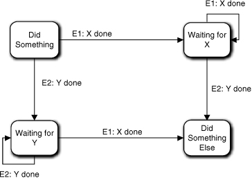
In other words, the solution depends upon how the requirements specify the collaboration. Now let’s look at how we might use handshaking to force X and Y to be done in pairs.
Sender to Receiver: I just did X.
Receiver to Sender: That’s nice.
Sender to Receiver: I just did Y.
Receiver to Sender: That’s nice.
Receiver (internally): Now I get to do my thing because X and Y are both complete.
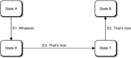
Here the premise is that the Receiver needs to do something after X is done but before Y is done. So the Receiver tells the Sender when it is safe to do Y. In this case, no “wait” state is required because the Sender will be unable to transition to the state that executes Y until it gets a confirmation from the Receiver. In other words, the handshaking protocol is built into the Sender by splitting the X and Y responsibilities and providing a transition between them to capture the sequencing constraint.
The Sender FSM might look something like Figure 17-3. The Sender’s basic life cycle is A → X → Y → B, and the Receiver has synchronized that life cycle with its own by providing the “That’s nice” acknowledgments. For its part, the Sender provides the “I just did X” and “I just did Y” announcements, which synchronize the Receiver’s life cycle to the Sender’s. Thus handshaking makes Sender and Receiver dance partners who keep in step through their respective life cycles.
Figure 17-3. Using handshaking announcements to “walk” through a life cycle
Now let’s look at a bit more context for the overall solution. Figure 17-4(a) represents a solution to a problem sequence where the overall solution requires activities to be executed in the order shown in the diagram. In particular, Object B should respond to Object A doing the Y behavior before it responds to Object C doing the C behavior. As an exercise, try to see if you can detect an ambiguity in the Sequence diagram concerning that constraint. (Hint: Suppose Object A and Object C execute concurrently and one has a much higher priority than the other.)
Figure 17-4. Using handshaking to ensure one Object state machine is ready to accept events from another
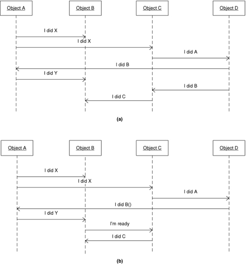
The problem lies in the order that Object B will consume the “I did Y” and “I did C” events. In a true asynchronous environment one cannot guarantee that the “I did Y” event will be consumed first. For example, if Object C executes at a much higher priority than ObjectA, then the action that generates “I did C” may complete and push that event onto the event queue long before the Object A action that generates “I did Y” completes and pushes that event. That’s because Object D essentially provides a fork in the processing with two different paths leading to Object B doing things. If the things that Object B does must be done in a predefined order, then we must provide some sort of synchronization for those two paths to make sure the “I did Y” and “I did C” events get pushed on the queue in the correct order.
An unambiguous solution is presented in Figure 17-4(b). Instead of Object D creating a processing fork by issuing two different events, there is now only a single possible sequence for putting events on the event queue. To do that we had to introduce a trivial bit of handshaking between Object B and Object C, where Object B tells Object C when it is ready to accept the “I did C” event by issuing the “I’m Ready” event.
Note that Object C’s C behavior is now triggered by the “I’m Ready” event rather than the “I did B” event. This gets back to the points made in the previous chapter about naming conventions and separation of message and method. The Object C state machine is unchanged; all we have done is associate a different event with the relevant transition. But because the context of the event generation has changed, it makes sense to use a different event message.
This also underscores my earlier point about constructing object state machines independent of context by making sure states have a problem space rationale. While we extract states and transitions with one eye on collaborations, the basic structure should be independent of context. The specific event that will trigger the transition is a context detail, while the state machine structure is an intrinsic problem space invariant of the underlying entity. That decoupling allows us to significantly change the overall solution flow of control without touching anything except where the triggering event is generated.
What about the fork produced when Object A generates two “I did X” events? That’s not a problem, because the only possible sequencing constraint that could be relevant is that Object B responds to “I did Y” after it responds to “I did X.” In this case Object A is generating both events, and it can’t possibly generate the “I did Y” event until after it receives the “I did B” event, and it can’t receive that event until it generates the “I did X” event to Object C. As long as Object A pushes the “I did X” event to Object B before it pushes the “I did X” event to Object C, the event queue will make things Just Work.5
This notion of daisy-chaining events through the event queue and synchronizing via handshaking is really crucial to good state machine design when state machines must interact, as object state machines do during collaborations. If you feel the least bit shaky about why the two forks in the original Collaboration diagram are a potential problem and how the second version fixes the problem with the second fork, you should spend some time “walking” the diagram as described in the preceding paragraph. You need to convince yourself that if events are pushed onto the event queue in a serial fashion everything will Just Work. (You also need to convince yourself that forks leading to different linear paths back to the same state machine can be a problem if the state machine itself has constraints on which responding action must be executed first.)
If you have never used state machines before, it will take awhile to fully appreciate what a marvelous invention the event queue is. The way in which the event queue and handshaking protocols combine to bring order to arbitrary delays and asynchronous processing has a quite magical aspect.6 Perhaps more important, once one gets the collaborations to work, the state machine approach tends to be very robust and often yields very simple runtime code. Recall the garage door opener example in Chapter 15 where the actions had almost no executable code. All the business rules were elegantly handled by the FSM structure and the sending of messages at the right time.)
One final point on handshaking. You will note that Figure 17-4(b) does not require us to add states to the Object C or Object B state machines. That’s because this example barely qualifies as handshaking; the “protocol” is simply that Object B tells Object C when it is ready to respond to Object C. This is actually the more common situation where one just reorganizes the daisy-chain of event generation. The handshaking issue was raised here because it is one possible reason for adding states to an object state machine.
Step 6: Add transitions.
This will usually be somewhat anticlimactic because just to recognize the states you will need to understand the overall collaborations, which implies knowledge of the sequencing constraints. Where you will encounter problems with this step is realizing that the behavior responsibilities may not map quite right when you try to map the requirements onto the state machine, which is exactly what happened with the garage door example when identifying the need to add {Closing, Opening} states. The door controller needed to do things while the door is moving, and those things didn’t quite hang together when we tried to map them into static {Open, Closed} states. In effect we had more transition circumstances than we could map between just two states.
There isn’t a lot of art here. Basically one is evaluating sequencing constraints and mapping them into a Statechart. The easy ones are those explicitly identified in requirements (including sequencing implicit in use cases). The green → yellow → red sequence of a traffic light is an example of a requirement that would likely be spelled out explicitly. The less obvious ones are those that are implicit in the nature of the problem space. That the pet cat could play with the garage door clicker until the motor burns out is less likely to be dealt with explicitly in the requirements.
Step 6A: Identify the life cycle invariants in the problem space.
A far more common problem is that the requirements are simply incomplete. It is assumed the developer has enough problem domain knowledge to fill in the gaps. Thus the specifications for an automated cooking oven where the food is loaded and unloaded by a robot are unlikely to mention that the oven door needs to be open before the robot loads the food. However, computers tend to be very literal minded and not very bright, so one must be very explicit about such details in the software specification. Therefore, the developer needs a systematic approach to adding transition constraints, and the best way of doing that is to look for invariants in the problem space. The question to answer before defining transitions is: In this problem context, is there some sequence of collaborations that is always done in the same order?
The operative phrase in that question is problem context. The issue is not some sequence of operations in a preconceived solution algorithm. Rather, it is about the problem space context in which the specific problem lives. Try to identify sequencing constraints that apply for any inputs to the solution that are reasonable. Thus, having the automatic oven’s door open is necessary regardless of what food will be cooked, the temperature it will be cooked at, and the duration of the cooking. Better yet, look for an invariant that applies to variations on the problem in hand. Best of all, look for an invariant that applies to a whole class of quite different problems. Before loading anything into a container one needs access to the container. That applies to refrigerators, grain silos, and garbage cans as well as ovens.
The more general the invariant is, the more robust its implementation will be in the face of requirements changes.
This was already mentioned a few chapters ago, but it was worth mentioning again. State machine transitions are static definitions of the structure. Capturing business rules and policies in static structure is usually a good idea because it simplifies the dynamics. But one downside is that static structure tends to be more difficult to modify when things change. So one wants to capture things about the business in static structure that are very unlikely to change unless the business itself changes (in which case the software as a whole will be in deep ka-ka).
Therefore, it is a good idea to step back a pace or two and mentally work through the anticipated collaborations to see what sequences are fixed by the nature of the problem space. One way to do this is to walk through the relevant use cases and understand why their steps are ordered in a particular way. (The final example at the end of this chapter does exactly that.) Is the order just a convenient description for a Turing environment, or is there something fundamental in the problem space that is dictating the sequence? The more abstract and generic the invariant seems to be, the more confidence you have that you have uncovered an intrinsic life cycle constraint. Fortunately, you already thought about problem space invariants when abstracting objects and responsibilities, which should make recognizing the particular spin for collaboration sequences easier to spot.
As mentioned previously, having a rough Collaboration diagram of the collaborations will tend to help. The Collaboration diagram presents a rather high level of view of the flow of control. Such a high-level view makes it easier to evaluate collaboration sequences around a particular object. That is, the view presents the sequences that might be, thus helping you to focus on those that must be.
Step 7: Associate events with the transitions.
This is where the overall solution dots are connected. Typically one assigns the event and determines where it will be generated at the same time. Being able to do that ensures that the state machines interact together correctly. By the time you get here, things should be pretty clear, because everything you have done so far was done with one eye on collaborations. So it is usually fairly routine to determine where the events are generated. In those cases where it is not all that clear, one can fall back on the formal DbC technique that we discussed previously.
Naturally, things don’t always go so smoothly. One common problem is that it seems like there are several different places where the event might be generated. This may be quite valid. For example, if you can generate errors from multiple contexts, you may have a single object that lives to process those errors (e.g., communicate with the user via a UI subsystem). A more common problem is that the precondition for transitioning to the receiving state is compound, and different conditions are satisfied in different places in the subsystem.
There are two ways to deal with this problem. One is to reconnect the messages so that the action where one condition is satisfied generates the event that triggers execution of the action where the other condition is satisfied. That is, one creates a single linear sequence for pushing events on the event queue such that the compound condition is incrementally satisfied in a cumulative fashion. Then one generates the event to the object in hand where the last condition of the compound condition is satisfied. This is the preferred method for most such situations. It is commonly referred to as daisy chaining.7
The second approach is to employ handshaking so that the receiver “waits” for events from both contexts to arrive before providing a response. Figure 17-1 was an example of this. As an alternative, one delegates the synchronization to another object. This object’s sole purpose is to “wait” for events announcing the various conditions, and then it generates the final event when all the conditions have been met. There are two reasons to avoid this approach. One is that it is more complicated. Another, more aesthetic reason is that one is “hard-wiring” the solution algorithm into an object implementation.
It is tempting to use a dedicated object when the individual condition contexts are unrelated, so there is no natural reason for one to be triggering the other. One may also choose this approach when daisy-chaining the sequence for the first approach seems too fragile (i.e., it is difficult to organize properly and is likely to have to change during maintenance). However, the real justification for this approach should be that an entity already exists in problem space with such synchronization as an intrinsic responsibility. Unfortunately, in most customer spaces that will be a human being whose responsibilities you need to anthropomorphize. Therefore, the dedicated object will probably be abstracted from the computing space or some esoteric conceptual space like design patterns.
Examples
Probably the most effective way to describe state machine design is to walk through the thought processes for some examples. We’ll use the ATM Controller example. You might want to go back and review the static descriptions of that example before continuing here.
Recalling the discussion of the ATM Controller, it was suggested that there really wasn’t a whole lot of processing and most of the objects were either hardware surrogates or dumb data holders. The most likely entities to have a life cycle relevant to the problem are the Dispatcher, Character Display, and Transaction. The Dispatcher clearly needs to understand the ordering of hardware operations and display; essentially, its role in the application is to act as traffic cop for messages from the user. Character Display needs to initialize the screen, process a stream of user keystrokes, update the screen, and let Dispatcher know when the user has finished entering a value. Superficially that sounds like a single procedure with a loop over reading keystrokes, but there is enough going on to take a closer look. More important, each of the activities is triggered externally, and there is a definite sequence in which they need to be done. Transaction does the real “banking” work, such as it is, by communicating with the Bank and triggering certain hardware activities.
ATM Controller: Character Display
First, let’s look at Character Display. In the rough Collaboration diagram in Figure 17-5, we see that the collaborations are not too complicated. Since Character Display will talk directly to the OS window manager to actually present a display, there is another player not shown. Typically, though, the OS window manager presents a serialized (synchronous) interface, and it is realized so we won’t bother showing it in the Collaboration diagram. So, the level of abstraction of the collaborations seems to be reasonable. There is a pretty clear order in these collaborations: The screen must be set up first, then the user types in a value, and finally the value is sent off to Dispatcher.
Figure 17-5. Preliminary cut at collaborations for the Character Display object
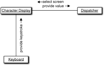
Are there any “hard states”? There are some obvious states related to sequencing operations, but there really aren’t any obvious, intrinsic states of being that leap out here. However, there are three clumps of processing that must be done in sequence based on the Collaboration diagram: initializing the screen through the OS window manager; processing keystrokes from the Keyboard; and extracting a value. Note that those responsibilities are invariant with the type of screen; we will do the same things for deposits and withdrawals. (Transfers are trickier, but we’ll get to them later.) Thus we can think of the conditions that prevail for executing each set of processing as a kind of “hard” state simply because it is so obvious and invariant.
Basically all Figure 17-6 represents is a mapping of the collaborations directly into states. (More precisely, I have mapped the collaboration responses into states by casting the conditions for executing the responses into states.) Note that the state names are all past tense descriptions of the response. This is a quite common naming convention for states where the state is named for the postcondition of executing the response. That is very consistent with the Moore model of state machines where, you no doubt will recall, the action is executed on entering the state. In this case, the state-of-being condition for the state happens to be pretty obvious. That is, most experienced developers would think of these as “hard” states. Therefore the diagram represents completion of the first three steps of the process suggested.
Figure 17-6. Preliminary state machine for Character Display
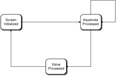
You have no doubt noticed that we have four transitions in the state machine but we had only three collaborations in the Collaboration diagram. Recall the discussion of modeling a keyboard from the section road map; this is the proper way to handle the keyboard input. As it happens, each transition involving Keystroke Processed represents a single collaboration with Keyboard. Note that we have effectively combined a gazillion states for individual keystroke sequences (the view described in the Part III road map example) into a single state. That legerdemain was accomplished by raising the level of abstraction of keystroke processing to an invariant that could be parameterized.
Now we have a state machine that seems to handle all the collaborations. In addition, it is quite easy to envision what the actions for each state do. The action for Screen Initialized reads the Display Specification, formats a buffer, keeps track of where the value will be in the buffer, and ships the buffer off to the OS window manager. The action for Keystroke Processed inserts the key value in the buffer and echoes the character to the right place in the display. The action for Value Processed extracts the full value from the buffer and ships it to Dispatcher. So everything seems to fit together properly.
Or does it? It is time to look for additional states and transitions beyond the obvious “hard” states and transitions. What about user errors? As long as the user catches typos, we can handle that in the Keystroke Processed action simply by doing the right thing in the buffer with the Backspace key value. In addition, for the simplistic ATM we have in mind we only have a numeric keyboard, so we don’t have to worry about alphanumeric typos. The code might start getting complicated and we might need a few smart private synchronous services to access the buffer, but that really doesn’t concern us here. That sort of processing is pure implementation and won’t affect our problem solution flow of control.
Don’t let action implementation complexity drive state machine design.
This segues to another important practical point about OO development in general. We use OO to solve an overall problem for the customer. We use OO techniques to isolate and encapsulate major program units so that their implementations can be decoupled for better maintainability. But once we have identified logically indivisible units in the overall solution flow of control, we pretty much wash our hands of those units’ implementations. Essentially we are making a trade-off in managing complexity whereby we ignore implementation details in order to get the big picture right.
Is there anything else in the problem space that we are overlooking? What about aborts? Is there a $nevermind key the user can press at any time to abort processing? Can the user do something dumb, like stomp away without retrieving their account card when informed they have insufficient funds? In such cases there may be situations where the Character Display could be left in a state that is not suitable for the next activity. This is a place where a Ready state may be useful as the state where the Character Display is always ready to accept a new screen request. One would have a transition from both Screen Initialized and Keystroke Processed to get to the Ready state to accommodate resets, aborts, and so on.8
The point here is that it’s best to step back and look at the whole problem space in addition to the specific use cases that seem relevant to the object in hand. When performing this sanity check, look for unusual scenarios. If you do, then the last question in the previous paragraph should make you realize that the state machine described so far won’t work properly for all situations.
The problem is quite common in software development—we tend to be myopic about “normal” use cases. What happens when the ATM user tries to make a withdrawal without sufficient funds? This state machine works fine for specifying the withdrawal amount. Dispatcher will then select a new screen to announce that there are insufficient funds. So far, so good. What’s wrong is that the announcement screen may not have an amount to fill in (we can’t assume the user will always want to try a lesser amount). Typically the user will be given a menu of keys to hit to decide what to do next. Character Display must map that keystroke into a message to send to Dispatcher.
In fact, we have screwed up big time here9 because there are probably several other screens (e.g., the start-up menu) where the user does not fill in a value or just selects a choice that Character Display returns to the Dispatcher. Our state machine is quite myopic about dealing only with the common Deposit and Withdrawal requests; nor does it seem to deal with the account selection needed for a Transfer.
There is no need to panic, though, because abstraction and cohesion come to the rescue, and this is easy to fix. One possibility is to subclass Character Display based on the sorts of screens one might have (e.g., get an amount, select a menu item, information dialog, etc., where each member of the category has unique value processing or lack of it). Then each subclass has a unique state machine to process its particular flavor of screen.
That’s a valid approach, and it would certainly be preferred for sets of complex screens. Effectively one creates subclasses to deal with the invariants of each screen category and employs Display Specification to provide details like text labels for individual category members. In this case, though, we need to look for a simpler solution since the UI is a cretin. In our simple ATM context, the user will do one of four mutually exclusive things:
- Press a single key that has special semantics in the screen context, such as a menu selection,
- Provide a value,
- Simply close the screen (via Enter), or
- Provide multiple values.
The Keystroke Processed state can do the right thing for the first case if it knows the first situation prevails. All we need is a type attribute in Display Specification that the Keystroke Processed action can access to decide what to do (i.e., map the key value to an event to send to Dispatcher or process the key value as a digit in the value in its buffer).
All that remains is to make sure our transition constraints will work properly for the single key case. They will if there is a transition from Keystroke Processed to Screen Initialized for the selection of the next screen. Such a transition would be triggered by the Dispatcher in response to the announcement that the special key was pressed. That’s fine except for one detail: the relationship to Display Specification. That relationship must be re-instantiated for the new screen to be displayed based on the user’s selection. Screen Initialized could do that.
OK, by applying KISS, our object and its state machine are kept simple and cohesive for the menu case. We already deal with the second and third activities, which leaves us with the Transfer transaction where the user is probably going to have to provide at least two values.
One could provide subclasses based on the number of values to retrieve. Or simply break up the screens to collect one value at a time. One could also provide an outer iteration around Value Processed and store values in attributes.
However, there is a much simpler solution, given our simplistic view of the character UI. Whether the user supplies one, two, or N values, they are just locations in our display buffer. The Display Specification can define the number of fields and their individual locations. That is, the user isn’t done (presses Enter) until all the fields have been provided. So Value Processed can use Display Specification to extract all the fields at once.
The only problem is keeping track of which field a given character provided by Keyboard is in within the Keystroke Processed action. Since the user will usually not fill each field with digits, there will have to be some way for the user to move to the next field, such as an arrow key. The Keystroke Processed action can take care of that since the arrow keystroke just indicates a predefined skip in the buffer. That skip defines where in the buffer the next character is stored and what position on the screen to echo the next character. Keystroke Processed is now somewhat more complicated, but none of that complexity affects flow of control; the same buffer is being modified, and the same buffer will be interpreted by Value Processed. Therefore, handling multiple fields can be done in the implementations of the existing actions.10
Now let’s think about how the user can screw things up. Fortunately, the UI is so simple there aren’t a lot of ways. The ATM may have a key called Main Menu or something that the user can click at any time to start over from the beginning, which is effectively an abort of current processing. The Keystroke Processed action can detect that key just like any other special key. It would probably be best to let Dispatcher figure out what to do with it, just like the other special keys.
We haven’t given the user a lot of keys to play with, so about the only problems around values entered will be an invalid value or a missing value. Detecting an invalid value will be the bank’s or some other object’s problem, and that will happen long after Character Display has done its thing by extracting the value. But a missing value is something Value Processed can detect. To be consistent it, would probably be best to simply announce the problem to Dispatcher and let it figure out what to do.
If the user hits arrow keys when only one value is required or hits the wrong arrow key to navigate to a field, it can probably be handled by simply ignoring them in Keystroke Processed.
The last problem is a time-out when the user failed to complete a transaction because a not-too-bright mugger lost patience. How the machine responds will depend on banking policy and, possibly, the hardware, so we won’t get into it here. There are two other very interesting things to think about for this scenario, though. One is where the time-out event is coming from. You seem to have forgotten something in your model, Grasshopper. You don’t have a Timer object. Shame on you.
Actually, you lucked out, Grasshopper, and there is no shame in it. In event-based processing, timers are so ubiquitous, especially in R-T/E, that they are regarded as an infrastructure object like event queues and we usually do not show them explicitly in the OOA model. So the time-out event will magically appear.
The next interesting question is: Who should respond to the time-out event? The problem is that the time-out probably has lots of implications besides the display. Certainly the processing of the current user transaction may need to be aborted. That gets tricky if we are in the middle of a withdrawal and the bank has already put a hold on the customer’s account pending the actual cash dispensing. But if the user is not responding at all, perhaps the whole session needs to be aborted. Then one needs to do something with the user’s ATM card and reset the entire machine so another customer can use it. Clearly, responding to the time-out is not a Character Display responsibility.
The potential for a universal reset of multiple ATM components is a distinct possibility, so we should think about this and how it would affect the Character Display. Assuming somebody else manages the overall reset, we can probably count on the fact that the reset will involve putting up a new screen, even if it is just the ATM logo for when no customer is actively using the machine.
So the overall strategy for managing errors is the same as handling special keys: Report it to Dispatcher and let Dispatcher figure out what to do next. That will very likely involve putting up a new screen, and theoretically that could happen when the Character Display is in any state.
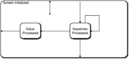
In Figure 17-7, the Screen Initialized state becomes a superstate. In this example we are only eliminating one transition, so the superstate notion is overkill. I was just demonstrating the sort of thinking that would lead to its discovery. Display Specification will have a type attribute to indicate the general category of screen to parameterize the action processing. Character Display will potentially generate a variety of events back to Dispatcher for different screen contexts (categories), and we will have to keep that in mind when we deal with Dispatcher’s state machine.
Figure 17-7. Updated FSM for Character Display object
Note that in this discussion did not follow the last three steps of the design process discretely. They became somewhat jumbled together in dealing with various special cases. That’s not terribly unusual. The approach described is intended to be a guideline. One should definitely address each step somehow, and it is often useful to do so in a systematic (ordered) way. But the order is not crucial. In any intellectual exercise that requires creative thinking, one sometimes needs to just go with the flow.
Also note that this discussion touched on a number of issues that imply iteration over work already done, from requirements elicitation through the static model to possibly other state machines. This sort of tweaking is inevitable in any complex human intellectual undertaking, so get used to it. Hopefully the general OO and specific MBD practices will minimize the amount of rework required. That minimization is a major reason why we use methodologies for design.
ATM Controller: Dispatcher
For the next example, let’s look at the ATM controller’s Dispatcher object. When we defined classes like Deposit, Withdrawal, and Card, we discussed possible functionality that we might ascribe to them. For the moment, try to forget all that as we “walk” through this example, because the point is that the methodology itself is self-correcting. We want to approach this as if we decided that Dispatcher was a controller object at the heart of the ATM that coordinates all messages. That is, every message goes to Dispatcher and is re-dispatched to the right place. So, tentatively, Dispatcher is a god object controlling everything else.
This is a common mistake when one has just enough knowledge to be dangerous. It’s possible to get the level of abstraction of the subsystem right (managing messages rather than banking semantics) but then get carried away with the notion of dispatching messages. Going hand-in-hand with the controller view, there is commonly an overreliance on use cases to drive structure. So rather than directly applying the process steps described earlier, we will take a more direct, use case-driven approach. That should demonstrate that applying basic design principles will get us to the right place anyway.
The first question we should ask ourselves is: What is the Dispatcher’s mission in life? It is actually the heart of the ATM Controller as we have defined it. As it happens, we have defined the ATM Controller to be rather simple-minded; all it understands is the routing of various messages to and from different hardware elements. As the name implies, the Dispatcher takes in an input message, reformats it, and forwards it to the right hardware element. If that were all that there was to it, then we would not need a state machine; a single method with an embedded switch statement would do it.
However, there is a bit more to it. There are some implicit rules about the ordering of input messages, such as the user must supply an amount via Character Display before the Cash Dispenser can be told to dispense cash. Intuitively the Dispatcher might seem like a good place to capture those rules in terms of transition constraints. So our basic life cycle is essentially the invariants of the sequence of interactions with the user (via Character Display), the Bank (via the Network), and the ATM hardware elements (Cash Dispenser, et al.). If we happen to have a suite of use cases that specify the user interactions, the logical place to start is by mapping their implied sequencing constraints into a state model. So let’s look at how that works for some informal use cases.
Use Case 1: User authentication.
User inserts ATM card in reader.
Validate card information with Bank.
If stolen, display message and eat card.
If invalid, display message and eject card.
If valid, display main menu.
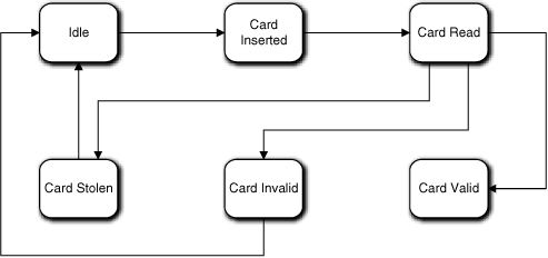
Let’s assume that the Dispatcher has an Idle state where it sits between users (i.e., when there is no card in the Card Reader). In this case it is pretty easy to map a state condition for each use case activity: Card Inserted; Card Read; Card Stolen; Card Invalid; and Card Valid. Each state will have a unique action to perform, in order: Request information from Card Reader; request validation from Bank (via Network); instruct Character Display to show a relevant display and then instruct Card Reader to eat card; instruct Character Display to show a relevant display message and then instruct Card Reader to eject card; instruct Character Display to display the main menu. Such an FSM is shown in Figure 17-8.
Figure 17-8. Preliminary state machine for Dispatcher
So far, so good. Note that since we are designing the intrinsic life cycle, we are not worried about what the specific events are that trigger the transitions or where they come from. Let’s look at the next use case.
Use Case 2: Withdrawal
User selects Withdrawal from main menu
Display amount request screen
Validate amount with Bank
If invalid, display message
If valid,
Dispense cash
Query additional transaction
If none, eject card, clear display, and print record
Else, display main menu
We can do pretty much the same thing for this use case, which just adds states and transitions to the state machine we already have, as shown in Figure 17-9.
Figure 17-9. Dispatcher state machine updated for withdrawal transaction
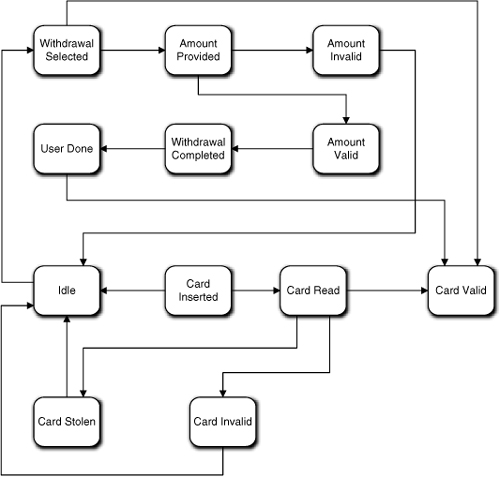
Note that the mapping of states to use case lines is not exactly 1:1 for this use case. That’s because we aren’t mapping activities; we are mapping states of being or conditions in a life cycle. In addition, we have one eye on the general sorts of collaborations we will have with other objects. Also note that the actions in most of our states are trivial; they just generate messages to hardware objects. That is exactly what Dispatcher is supposed to be doing. So the states are just way points where Dispatcher waits for an announcement that some triggered activity has completed.
There is a bit of trickiness here in that if the user has another transaction, we would have to go back to the Card Valid state. That’s because that is where the message to display the main menu is requested so we can dispatch to a menu selection. In other words, we are reusing the state and its action. But there is a problem with the state name because for this use case we aren’t validating the card. So, if we are going to be properly anal retentive about the state model, we need a more general name that covers both contexts, such as Ready For Transaction.
Alas, proper state names are the least of our problems here. We should be worried about the size of the state model because we have twelve states and at least two more major uses cases—Deposit and Transfer—to go yet. Also, Card Valid is beginning to look more like Idle than Idle itself. Finally, we might also be concerned about a pattern emerging around the Ready For Transaction (nee Card Valid) state. The cycle for each use case starts and ends with the Ready For Transaction state if the user has multiple transactions. Each of our other transaction use cases will very likely have the same pattern around that state so, we will end up with a “flower petal” pattern where multiple mini-cycles look like petals on a flower around the central state (the stem). Such a pattern suggests blobs of unrelated processing, and that suggests a lack of cohesion in the object abstraction. Similarly, large state models suggest too many disparate behaviors.
So a reviewer is going to want a lot of solid justification for such a state machine. In this case we might justify it on the basis that most of the states don’t actually do anything in terms of algorithmic processing; they are basically placeholders for the transition constraints on the sequencing. While that can be a valid justification, it is very thin, and we should still look for some way to simplify the state model. There are basically two ways to do that.
One approach is delegation, where we allocate some of Dispatcher’s responsibilities to other objects. For example, the entire first use case might be handled by the Card object because it is a one-time validation when the user’s card is inserted. That is, when the Card is created, it could “walk” the validation sequence and, if valid, could then turn over responsibility for managing the main menu and subsequent transactions to the Dispatcher or Transaction. Before doing that, though, we need to make sure such a delegation is reasonable in the problem space.
We can rationalize that by stepping up a level in abstraction and looking at what the use case itself is doing. It is validating a user whose surrogate here is Card. At that level, validation seems like a reasonable responsibility for Card, assuming a bit of anthropomorphization. What about Dispatcher? Are we usurping its mission of talking to the hardware (i.e., bleeding cohesion across objects)? Yes, but all we are really doing is limiting which hardware messages it coordinates from the overall problem perspective. That is, Dispatcher doesn’t really know anything about the semantics of the messages; it just enforces some sequencing and mapping rules for the messages that it does process. The delegation decision is made on the basis of the semantics of the messages themselves.
So we can rationalize such a delegation in the problem space. But a good sanity check is whether doing so will disrupt our existing model. Card already has relationships with Network and Card Reader, so those collaborations are OK. However, to implement the use case Card would also have to collaborate directly with Character Display. It is hard to rationalize any relationship navigation path to get there with the present Class Model. Transaction might not even exist when the validation is done, and connecting to Dispatcher through the Card Reader hardware doesn’t provide a warm and fuzzy feeling.11 However, we can fix that by adding a direct relationship between Card and Character Display or Dispatcher. That isn’t what many would regard as a major modeling change, so I don’t think there is a problem with the delegation from that viewpoint. So in this case we could add the relationship12 and create a state model for Card that handled the first use case. That state model would be exactly the same as the “flower petal” for the first use case.
Unfortunately, that still leaves us with the flower petal problem for the other transactions. Can we delegate the transaction use cases individually? How astute of you, Grasshopper. Yes, and we already have convenient subclasses of Transaction that could hold state models for the sequencing constraints of each transaction. If we can rationalize delegation to Card, we can certainly rationalize delegation to Transaction subclasses for each transaction use case. Nor will such a delegation disrupt the model very much.
As a practical matter, any experienced OO developer would have recognized these delegations as soon as the use cases were inspected. We walked through developing the Dispatcher state model this way deliberately because this kind of “flower petal” complexity crops up fairly often when requirements are not as conveniently organized as the presentation of the use cases. The real issue here is recognizing the problem when it does occur and doing something about it. As it happens, we probably would have recognized the problem much earlier when we identified the responsibilities of Card and the Transaction subclasses in the Class model. This is what was meant about getting to the right place even if one gets off on the wrong foot. When warning flags like large, complex state machines and suspicious life cycle patterns show up, we are forced to step back and look at the big picture again.
So what is the second way to solve the problem? To answer this question we need to think about whether we need Dispatcher at all now. Superficially there is nothing for it to do now if the main use cases are delegated to objects that collaborate directly with the hardware.13 An interesting question, though, is whether we want those objects to talk directly to the hardware. Recall that our original justification for Dispatcher was to map messages to the specific hardware elements. In that respect we are usurping Dispatcher’s decoupling prerogatives if we make other objects aware of specific hardware elements.
As a practical matter this does not have to be a big deal, because in each case (so far) the object collaborates with Character Display and whatever hardware element is on the end of a particular relationship. So we can let Card Reader, Cash Dispenser, et al. provide the formatting appropriate for the hardware element. Then the objects generating those messages don’t really have to know about specific hardware; they can simply announce what they have done to whoever is there. Therefore, a full delegation solution where we essentially eliminate the need for Dispatcher is a viable solution in this specific situation.
But the question we need to ask now is: Are there still some sequencing constraints that are better enforced centrally than in the individual delegates we have defined? In other words, are there some higher-level invariants common across use cases that we can capture in Dispatcher?
The answer to these questions lies in abstracting the problem space. Finding a higher level of abstraction for the state model is the second way to resolve the complexity problem. Look at the given uses cases and imagine two more for deposits and transfers that will be very similar to the withdrawal use case. See if you can identify some higher-level sequencing that is common to them all. (Hint: Find a way to describe specific operations so that the same description could be substituted in each use case. That may require combining some detailed use case steps.)
In this case there are three things each use case does if one steps back far enough to view them. They each retrieve data from the user, they each display something, and they each trigger or authorize some hardware activity. The data is different, the displays are different, and the activities are different, but each use case controls the sequencing of doing those things. This allows us to abstract the collaborations to “give me my data”; “put up my display”; and “do my activity.” An object initiating such collaborations controls their order, but it doesn’t need to know anything about the details of where the data is, what the display is, what activity is done, or who performs the activity. Therefore, Dispatcher could act as middleman and provide a mapping for “my” to the details.
The FSM in Figure 17-10 captures the sequencing of these basic activities. If you compare it to the FSM in Figure 17-9—which would now be in Card or Transaction—you can probably readily imagine the handshaking that would go on to have these two FSMs march through the transaction in lockstep. (This FSM has fewer states, but the Transaction has other collaborations.)
Figure 17-10. Dispatcher state machine after delegating processing to other objects and capturing invariants
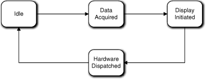
This FSM is not really an alternative to delegation, though; it is complementary to the Transaction FSM. Just from the state names we can tell that this FSM is at a higher-level of abstraction. Given the way we arrived at it, it represents a quite different view that is really about how the hardware elements are coordinated. So we probably need this FSM in addition to the delegation. The value of that will become clear when we look a bit deeper into the problem.
That FSM is fine as far as it goes, but some activities are missing. For one thing, the ATM logo needs to be displayed when there is no active customer. Not a big deal; we can do that in the Idle state. Just because we have a Display Initiated state does not mean that every screen needs to be triggered from that state. So far the rules and policies that are relevant to Display Initiated are those related to displaying a transaction screen.14
What about things like the Main Menu screen most ATMs have? That screen needs to be shown first thing when the user successfully logs in and also when the user completes a transaction. The first question is: Who manages that? The short answer is: Nobody. Stop thinking like a C programmer, Grasshopper. When the ATM card is successfully read, that screen can be triggered from the Card Valid state of Figure 17-8. All we need to do is add a transition from Idle directly to Display Initiated. The Display Initiated state will do exactly the sorts of things it does to put up a transaction screen.
What is broken in that situation is the transition from Hardware Dispatched to Idle in our new Dispatcher FSM. When the hardware is done, that signals the end of the transaction and we want to put up the main menu. So the transition should go from Hardware Dispatched to Display Initiated.
But what about those special keys the customer presses when selecting a menu item? To answer this we have to think about what those keys might mean. For our simple-minded ATM Controller, let’s assume that they mean either the user is completely done with the ATM and wants to go hit the bars, or the user selects another transaction. Both of these bring up some interesting issues for the ATM in general and this FSM in particular.
If the user wants to go away, the ATM needs to give back the ATM card and return to the Idle state. We could do that by simply providing a transition from Display Initiated to Idle and let the Idle state check the Card Reader for a card and, if so, eject it. That’s not a good idea because the Card Reader might jam and we would need to process the error. However, we know that Hardware Dispatched could have a malfunction for any hardware operation, so it probably will be set up to deal with that already. (It isn’t now because we haven’t gotten there yet, but it should be.)
So for this situation we should take advantage of Hardware Dispatched to eject the card from Card Reader. This means we need a direct transition from Display Initiated to Hardware Dispatched. And when the “card ejected OK” message comes back from Card Reader, that event should transition from Hardware Dispatched to Idle. So we still need the transition to Idle; we just use it for a different event context.
For the situation where the user selects a new transaction, we have some stuff to do. We need to delete the current Transaction object (if there is one), instantiate the new Transaction object, and turn control of the processing over to it. We also have to instantiate the proper relationships to the Transaction object. Together, those are a whole new set of nontrivial rules and policies. If Dispatcher owns them, we need a new state, say, Transaction Instantiated.
Let’s say we do that. We need a transition from Display Initiated to Transaction Instantiated that will be triggered by a “new transaction” message for the selection. Once Transaction takes control, the first thing it will do is try to put up the right screen to get the user’s data. So we also need a transition from Transaction Instantiated back to Display Initiated. So far so good.
One can argue, though, that giving Dispatcher responsibility for managing the instantiation of Transactions and their relationships could detract from the cohesion of Dispatcher. In fact, one reason we have several flavors of established design patterns for object construction is because the rules and policies of instantiation typically are quite different than those that govern collaboration. That’s a valid argument, and you wouldn’t be docked for relegating that to a separate “factory” object. It would be the case if the associated processing was complex or unique decisions had to be made to instantiate properly; that clearly would be fodder for isolation and encapsulation.
In this situation, though, there probably isn’t much to it. As a practical matter we only have one Transaction at a time, and the only knowledge it has that depends on identity it gets from the user through the display (i.e., an amount). So we would probably instantiate one of each flavor of the Transaction subclass at start-up. Then all we have to do to “create” a transaction is instantiate two relationships to the relevant instance for the Transaction subclass object. That’s not rocket science, so I would probably opt for simplicity and do that in a Dispatcher state.
We have one problem left with this state machine. There is the potential for malfunctions in the hardware and some possible user errors so far. Hardware malfunctions are probably terminal and one needs the same special processing around all of them that leads to an ATM belly-up shutdown. At a minimum that processing is going to involve putting up a screen to tell the user there is a problem; telling the bank a repair is needed; ejecting the ATM card (if possible); and shutting down. We could put that processing in a single Dispatcher state, but it would be better if a dedicated Hardware Error object owned that processing.
There are several reasons why. Error processing of that level of complexity is not something that seems like the Dispatcher should own; it is quite different than the rest of Dispatcher’s processing. It probably requires handshaking with the bank. There may be a required sequencing for the hardware shutdown and there are other sequencing rules (e.g., the ATM card should be ejected before shutting down the machine). So we don’t want to clutter Dispatcher’s state machine with all that. Those sequencing rules apply to a specific context, error processing and graceful shutdown, so they should be encapsulated. So make a note, Grasshopper, that the Class diagram needs to be updated for the new object. Finally, the FSM itself is getting pretty big.
It might still be convenient and consistent to have a Malfunctioned state in the Dispatcher FSM, though. That state would trigger processing by relaying the error to the external Hardware Error object. There would be a transition from Hardware Dispatched to that state. There would probably be a transition from that state to Display Initialized as well since the user needs to be told about the problem. Such a state makes it explicit how a hardware malfunction fits into the overall scheme of things without burdening Dispatcher with the details. In addition, the Dispatcher is still the central point for hardware communications.
What about user errors? From the discussion of Character Display, we know the big one, an invalid amount, will be handled by Transaction while the little ones (typos) will be handled internally by Character Display. So there really isn’t anything to manage for Dispatcher.
Figure 17-11 represents the updated version of Figure 17-10. The most obvious difference is that there are a lot of transitions, and they are mostly around Display Initiated. The number of transitions really isn’t a problem. It just looks messy because we haven’t put specific events on the transitions. If there were events, they would be quite different because they reflect very different triggering contexts.
Figure 17-11. Dispatcher state machine updated to handle hardware malfunctions and transaction instantiation
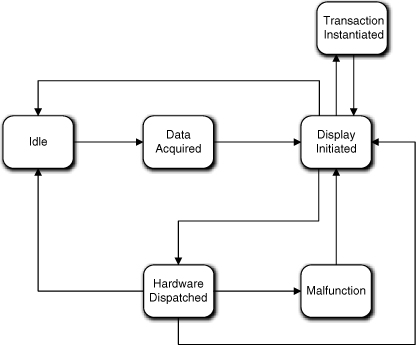
The central role of Display Initiated is somewhat more worrisome because the life cycle tends to take on a “spider” pattern around it. A reviewer is going to look very closely at such a state machine. But one can rationalize that this is one of those situations where such a pattern can be justified. This is because the display has a central role in both the way transactions are processed and the way special situations like errors are processed. I can also argue that the Dispatcher’s mission is to decouple banking transaction processing from the hardware. To do that, Dispatcher manages messages, and many of those messages are necessarily directed to the display. More important, Dispatcher is enforcing constraints on different sequences of messages where each sequence happens to involve a display.
Before leaving Dispatcher, we need to discuss the current vision of what the Hardware Dispatched state action actually does. Basically, it interprets a code in the incoming event data packet and generates an event with a data packet that is a copy of everything in the incoming event data packet except the code Dispatcher interprets. When interpreting the code, the Dispatcher also selects the right hardware surrogate to target, probably via a table lookup. The hardware surrogate will interpret the data packet and convert it into a physical hardware read or write.
As a practical matter, though, objects like Cash Dispenser are unlikely to have state machines. Ultimately one is reading or writing values in hardware registers to control the hardware. A hardware register is just a memory location, like an object attribute. For all practical purposes, all one is doing is reading and writing knowledge, which is inherently a synchronous activity. So the “methods” of hardware surrogates like Cash Dispenser are really just smart setters for the hardware’s knowledge.
In fact, device drivers largely reflect this; they provide a synchronous interface where each command is implemented separately from other interface commands. So whether Dispatcher calls a Cash Dispenser method, invokes a device drive method directly, or does direct register writes, the “events” to the hardware are really going to be synchronous service setters. By providing hardware surrogates like Cash Dispenser we are introducing additional decoupling from the specific hardware registers, but we should think of the messages as synchronous services to be invoked by Dispatcher.
There are a couple of important points about this discussion of Dispatcher worth reviewing. We have subtly changed the mission of Dispatcher. Although we didn’t mention it explicitly, Transaction and Card talk directly to the network port rather than through Dispatcher. That’s because some of the transitions are necessarily triggered by the bank, and once one has delegated management of the individual transactions it makes sense for the network events to go directly to those FSMs since no interpretation is needed.
It also provides more coordination of the processing than simple message re-dispatch. For example, we have accommodated several bits of new functionality by defining more transitions and associating different contexts (events) with those transitions. Nonetheless, Dispatcher doesn’t really do much except the original message reformatting we intended.
To that extent, Dispatcher is an excellent example of how FSMs can manage sequential processing without executable statements. All of that coordination is done through the handshaking that provides events for the transitions. As a result, there is no explicit central coordination of the processing for the various use case scenarios; it is all managed through FSM transition structure and FSM interactions.
Such an elegant solution is enabled in no small part by the way we managed abstraction. The Dispatcher FSM migrates through its states in lockstep with the Transaction FSM. But that synchronization was not the primary goal of the FSM designs. We came up with the Dispatcher FSM working independently with the use cases at a different level of abstraction where we extracted invariants from the set of use cases in a holistic fashion. It was those invariants that we captured in Figure 17-10 that enabled the FSMs to play together.
Another important point is that we were able to accommodate a lot of additional processing without changing those core states. We added a couple of states and several transitions, but we didn’t change the original core action responsibilities of the states or their roles in the original transaction use cases. If you think about it, we accommodated a boatload of additional scenario content between Figures 17-9 and 17-10, but the FSM differences are rather minor and the original actions are essentially the same. So this example also demonstrates the truth of an assertion made earlier in the Part III road map: It is not easy to get interacting FSMs right, but once they are right they tend to be very robust in the face of volatile requirements.
ATM Controller: Deposit
Previously we tentatively identified a Deposit subclass of Transaction to capture the semantics of the user making a deposit. The analysis is pretty much the same as what we decided to do for the Withdrawal use case. In fact, this is one of the interesting issues about this life cycle, but we’re getting ahead of the story.
We are well along that road with the invariants just discussed: display a screen, get user data, and request a hardware action. That’s fine for pinning down the level of abstraction and identifying “hard” states. But it sounds a bit procedural because it is oriented around telling others what to do. That’s probably OK here because the mission of this object in the problem space is to enforce problem space rules about the sequencing of activities. That is, the object itself doesn’t really do much except to format and dispatch messages in the right order.
So let’s look at the use case and see how this vision fits. For this object, the following use case could be relevant.15
Use Case 3: Deposit
User selects Deposit from main menu
Display amount request screen
If invalid, display message
If valid,
Accept deposit envelope
Query additional transaction
If none, eject card, clear display, and print record
Else, display main menu
You will note that this use case is almost exactly like the Withdrawal use case. This should not be a big surprise because of the invariants we identified. So we have the basic display, data access, and hardware access sequencing. We also have some cleanup to do at particular points in the processing of the transaction. Note that the processing is quite linear except for the cleanup activities. Intuitively, it seems obvious that the use case steps also define constraints in the sequencing that must be honored (e.g., we must validate the amount before dispensing cash). So tentatively we might expect something like Figure 17-12.
Figure 17-12. Preliminary Deposit state machine
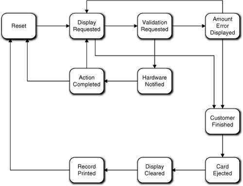
Note that the linearity is boggled by the transitions around Amount Error Displayed. Why not use a superstate for that? The main reason is that it can only be reached from one state. We use superstates to eliminate transitions from several states going to one state.
Now to the point of this exercise: What’s wrong with this state machine?
The design process says we should check for activities that can be combined in a single state action. Should ejecting the card, clearing the display, and printing the record be in their own states? In this case they are done as a group only after the customer is finished with the ATM. In fact, it doesn’t matter what order they are done in, so there is no intrinsic sequencing constraint to enforce among them. Therefore, we should get rid of the Card Ejected, Screen Cleared, and Record Printed states with their transitions and let the Customer Finished state action just push three different events onto the queue at the same time.16 The modified FSM is shown in Figure 17-13.
Figure 17-13. Update Deposit state machine to eliminate states with same condition
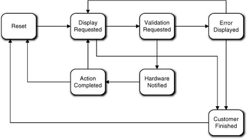
Fair enough. But now we still have six states, yet when we talked about invariants across transactions we only came up with “display a screen,” “get user data,” and “request hardware action.” So can we eliminate more states? Probably not, for a couple of reasons. First, the invariants don’t describe everything the transaction needs to do. For example, we have to process errors. OK, maybe we could add another invariant activity, “process error,” because all the transactions are likely to need to do that. But that won’t work so well because of the second reason.
The second problem is that our Transaction object needs to collaborate with other objects. For example, to validate the amount it has to talk to the Bank at the other end of the network connection. So conceptually we may just have “request hardware action,” but in practice we need to define what that means in terms of collaborations. In this case half of our states can be viewed as simply supporting collaboration sequencing constraints. To put it another way, half our states reflect our Deposit just waiting for someone else to do the grunt work. Thus they exist to support the sort of handshaking that was discussed previously.
That handshaking sneaked into the FSM as a fait accompli because we mapped those states to the use case steps. The use case was probably subdivided into steps because the customer already understands the kinds of protocols that would be required to deal with the deposit as a manual teller activity. In practice, the state machine designer would keep one eye on the other state machines and would verify that the states resulting from that mapping really do accommodate the necessary exchanges of synchronization messages. The handy way to do that is to scribble notes to oneself on a white board Collaboration diagram.
However, the invariants might be reflected in another way. Compare Use Case 2 and Use Case 3. They are virtually identical. The only difference lies in some specific references such as “Deposit” versus “Withdrawal” and “Accept deposit envelope” versus “Dispense cash” in two activity lines and the validation activity in the Withdrawal. From a software design viewpoint we could combine those two uses cases as:
Use Case 4: Transaction
User selects choice from main menu
Display amount request screen
If Withdrawal, validate amount with Bank
If invalid, display message and exit
Execute transaction in hardware
Query additional transaction
If none, eject card, clear display, and print record
Else, display main menu
Again, use case purists will get bent out of shape here, but we are trying to make a point about software design, not requirements specification. Now go back and look at the last state machine proposed and determine what changes need to be made to accommodate this use case. Answer: The only change to the state machine would be to accommodate the validation.
So we could actually use the state machine that was developed for Withdrawal provided there was a transition to go directly from Amount Provided to Hardware Execution Completed (aka Cash Dispensed). There is nothing in that state machine that depends upon whether the transaction is a Deposit or a Withdrawal except the processing around validation. There will be a several differences in the actions associated with the states because the right event messages need to be generated to the right collaboration objects. But those don’t show up at this level of abstraction because we are using the FSM to capture invariants of the processing.
We have seen exactly this sort of situation before when we discussed subclassing and state machines. One has a set of state machines for the subclasses that are almost the same for all the subclasses except a few local states and the actual actions associated with the states. We can use the convenience of a superclass state machine to describe the states and transitions that are common among each of the subclass state machines and only need to define the Amount Valid and Amount Invalid states and transitions in the Withdrawal subclass.17 Note that this sort of thing maps very nicely to use case variants whenever the variants can be expressed in subclasses, as is the case here.
The only remotely tricky processing would be around a Transfer. That requires two values to be processed and the message goes to the network port hardware rather than an ATM hardware element. Because of the way we have currently defined Dispatcher, the routing is not a problem and the values are just passed through from the Character Display. So all we have is a slightly different formatting of the event data packet in the state action. Alas, that is a theoretical toe stubber.
If you recall the rules for FSAs, the alphabet on each transition to a given state must be identical. So the Amount Provided state technically can’t be the same for Deposit/Withdrawal and Transfer. As it happens, we have a clever way around this in the OO paradigm. We can make the event data packet itself an ADT, which hides the specific implementation and content behind abstraction. That allows us to have the consuming action “parse” the data packet based on embedded codes. However, one needs to be cautious about this: It hides a synchronization issue between sender and receiver because the encoding/decoding of the data packet needs to be consistent.
This sort of synchronization is significant to the basic problem solution here, so it should be more explicitly dealt with in the solution model. For this reason we want the Amount Provided state to be a subclass state. A different event will have to be used in the subclass state machines, which requires that the relationship navigation must be explicit to the subclass.
If you have committed the ATM Class Model to memory you will note that each Transaction subclass already has its own associations, which means that all clients will be navigating those specific associations so there will be no polymorphic events. It also enables us to employ different event data packets because conceptually each subclass state machine is unique.
We have gone through a rather laborious analysis of these examples, including some deliberate false starts, intentionally to try to demonstrate how an experienced state machine developer thinks about state machines. Developing state machines is not very intuitive to the newcomer, so the extra verbosity is the best way of conveying the proper mindset.