
Chapter 18. Abstract Action Languages
I have often wished that there were a language in which it would be impossible to tell a lie.
—G. C. Lichtenberg
We have spent most of this book discussing static structure. Even the chapters on FSMs were primarily about using state machine transitions to capture problem space sequencing rules in static structure. Eventually, though, we need to describe what the software does. An AAL describes what a behavior responsibility does within an individual state machine action.
The AALs are text based and superficially look a lot like 3GLs, because what they describe is primarily algorithmic and is expressed in terms of algorithmic computation. That is, the business rules that are left over after capturing as much as possible of the problem space in static structure are invariably fairly low-level computations. Depreciation is defined by this formula. The memory manager employs that least recently used algorithm. Half a century of experience has demonstrated that the 3GLs are a pretty good way to express computation.
Because the AALs borrow heavily from 3GLs, the learning curve for AALs tends to be very short for anyone who has even modest conventional programming experience. Consequently, this is going to be the shortest chapter in the book. In fact, the real goals of this chapter are twofold:
- Describe how AALs differ from 3GLs
- Demonstrate that the implementation details littering 3GL code are not relevant at the 4GL level
The first is the easiest because it really comes down to the level of abstraction. UML combined with an AAL that is compliant with OMG’s execution semantics is a true 4GL. What makes it a 4GL is independence from specific computing environments.1 That independence is only possible if we raise the level of abstraction to a very high level that would map just as easily to an abacus and smoke signals as it would to a modern desktop hooked into the web. As we shall see shortly, modern AALs are very simple and very abstract.
But for that abstraction to work it must be tied to some conventional notion of problem solving in the problem domain. This is why we spent so much time on problem space abstraction to define the static structure. As we shall see, the AAL syntax is very closely integrated with UML graphical syntax. Since the static description is militantly rooted in the customer problem space, we can tie the behavioral description directly to that skeleton rather than the hardware computational models. So while the AAL syntax may look a lot like 3GL syntax and things like arithmetic operators are used the same way, the AAL is inextricably bound to the rest of the UML graphical model.
In no small part, the simplicity and abstraction of AALs is due to OOA/D design principles that lead to logically indivisible responsibilities. Everything we have talked about so far leads to small, narrowly defined state actions that are completely self-contained. So when we set about describing what goes on within a state machine action, we don’t have a whole lot of complexity to describe, which enables us to focus on the customer’s view of the necessary processing.
This segues to the second goal of this chapter: demonstrating that the solution description need not be encumbered by computing space paraphernalia. Shedding computing space technologies, techniques, and practices is often the most difficult thing for novices to the OO paradigm to do. The reality is that OO designs are simple. But that can only be demonstrated by carrying through some of our examples where we can see how little executable AAL code is needed.
AALs and ADFDs
Today almost everyone uses text-based AALs, but this was not always the case. Originally, before UML, the modeling notations were fully graphical and chose to express behavior in a special diagram called an Action Data Flow Diagram (ADFD). It was closely based on the traditional Data Flow Diagram (DFD) used in many Structured Programming methodologies. Text-based AALs replaced ADFDs primarily because they were easier to change during maintenance and because text is actually a more compact means of describing algorithmic processing. But a brief summary is worthwhile because typical AAL syntax is rooted in the ADFD notation.
An ADFD had essentially three primary elements:2
• Process. A fundamental, self-contained, logically indivisible unit of behavior. A process operated on input data to produce output data. In DFDs these were all what we would call transform processes. In ADFDs, though, they could be any of the fundamental processes discussed in the Part III road map.
• Data flow. A connection between processes that represented a flow of data from one process to another. In effect this was a message data packet.
• Data store. A set of related state variables. This was another divergence between Structured DFDs and OO ADFDs. In Structured Programming the data store was usually a database record while in the OO context it was an object.
The basic idea of the original DFDs was that an application could be described as flows of data among processes. ADFDs introduced the idea of special kinds of processes and objects as data stores.
Unfortunately, this led to some amusing verbosity in the early AALs that simply mapped ADFD syntax to text syntax. For example, if we quite literally mapped each process to a text statement in the syntax, and we had specialized processes to read, modify, and write attribute values, a simple increment of an attribute might require three separate statements like:
tmp = Customer.age; // read accessor
tmp = tmp + 1; // transform
Customer.age = tmp; //write accessor
Fortunately, modern AALs take advantage of compact syntax to perform such an increment in a single statement. They also do a better job of defining what a fundamental process is. Nonetheless most AALs are easily mapped directly into an ADFD representation. With UML the ADFD became an Activity diagram with specialized processes.
There is no inherent restriction on the linguistic model for the language (declarative, imperative, predicate, etc.) but imperative AALs are the most common. In fact, most AALs are based upon existing procedural languages expressly to provide familiarity for converts from traditional development. However, AALs are very abstract, so they offer far fewer syntactic options than typical 3GLs. AALs tend to be set oriented for their operations because OOA/D models are very focused on relationship sets. One language was so set oriented that it originally had no construct for element-by-element iteration (e.g., a C “for” loop).
AAL Syntax
The AAL used in this book is a generic sort of syntax that does not represent any particular AAL.3 Thus almost all AALs have individual statements for generating events, creating instances, instantiating relationships, and accessing knowledge. The biggest single difference between ADFDs and AALs is that the AALs usually provide individual arithmetic and logical operators so we can embed what trivial test and transform processes do directly in the AAL code. That is, 3GL-like expressions may be mapped into ADFD transforms (or vice versa, depending upon our perspective). The AALs also usually supply additional syntax for things like iteration.
The AALs are pretty simple because of their high level of abstraction; in some cases the entire AAL syntax definition fits on a single page. In addition, the syntactic elements are fairly intuitive once we are familiar with the rest of the elements of a UML Class Model. Table 18-1 describes the syntax. To keep things simple some of the options for more exotic situations (e.g., selecting a relationship for navigation based on role) are omitted.
Table 18-1. Summary of AAL Syntax in Terms of ADFD Processes
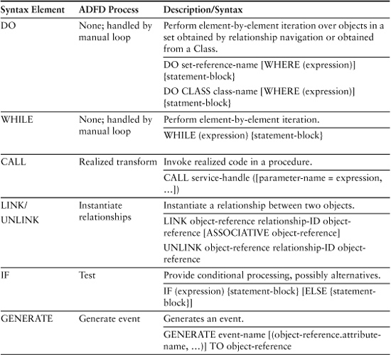

Attribute assignments are done with the write accessor on the left of an “=” and the arithmetic/logical expression with read accessors that computes a value on the right. In my simple syntax statements are terminated by a semicolon. The conventions for Table 18-1 are: CAPITALS indicate keywords; [] denote optional elements; and ellipses indicate 0 or more repetitions.
An interesting question is: If AALs are so abstract, why do they have bitwise operators? The operators are introduced simply to enable us to write basic transforms inline in the AAL code. As it happens, this AAL is explicitly specified for use in R-T/ E environments, and in that domain bitwise operations are equivalent to the + and – of debits and credits in an accounting domain.
Another, related question is: If AALs are so abstract and platform independent, why hasn’t OMG blessed a single AAL as the standard for all applications? One reason is that AALs tend to be domain specific. Thus, an AAL designed explicitly for accounting domains might have a special operator for allocations. That is, one uses the AAL that best fits the way the customer thinks about problems. In contrast, we often choose 3GLs based on computing domain criteria, such as performance.
Examples
Garage Door Opener
Recall the garage door example where we had an FSM with four states: Open, Opening, Closed, and Closing. Let’s assume we have a Motor object whose job it is to write to the hardware. Assume the hardware has one 2-bit register with two 1-bit fields for direction (0 = forward or open; 1 = reverse or close) and initiate (0 = stop; 1 = start).4 Further assume we model Motor with a register attribute and provide setDirection(), start(), and Stop() as the interface for accessing that knowledge. Finally, let’s assume the GarageDoor is connected to Motor via a 1:1 association called A1.
Let’s first consider the object state machine we discussed previously. What is the AAL for each of the states? For the Open state, all we need to do is tell the Motor to stop:
ref = THIS -> A1; // navigate to the Motor over the A1 association
ref.stop(); // invoke setter
The association navigation simply says that we should obtain a reference to the object on the other end of the A1 association. In this case, that is pretty simple since the association is 1:1. What happens if you screw up and the object at the end of the association doesn’t have a stop() synchronous service? The same thing that would happen in any a strongly typed OOP—the model simulator or transformation engine would say something rude about your skill with AAL, because the Class diagram will tell it what is actually on the other end and what properties it has.
Similarly, for the Closed state we need to tell it to stop.
ref = THIS -> A1; // navigate to the Motor
ref.stop(); // invoke setter
For the Opening state we need to set the direction and start the Motor.
ref = THIS -> A1; // navigate to the Motor
ref.stop(); // in case Clicker was clicked again
ref.setDirection(0); // invoke setter
ref.start(); // invoke setter
Finally, for the Closing state we need to do the same thing with a different direction.
ref = THIS -> A1; // navigate to Motor
ref.stop(); // in case Clicker was clicked again
ref.setDirection(1); // invoke setter
ref.start(); // invoke setter
In an AAL we usually have the same freedom to provide symbolic literals for the direction that we would have in a typical 3GL.
So let’s look at the code for the Motor’s synchronous services. What do we need to do to stop the motor? We need to set the initiate field in our register to 0. Let’s assume the initiate field is the least significant bit and the direction field is the second bit. Do we care about the direction? No, because we explicitly set it correctly in the GarageDoor state machine whenever we start it, so we don’t need to worry about read-modify-write. So our stop() setter is pretty basic:
stop()
register = 0;
which ensures the initiate bit is set to 0. Similarly, setDirection is always done before start(), so we can overwrite the Initiate field. But when we write a 1 we need to make sure it gets into the 2nd bit. One way to do that is like this:
setDirection (direction)
Register = direction * 2;
Since twice 0 is still 0, this is fine for forward. For reverse, 2 * 1 = 2, which is 10 in binary and will set the second bit to 1. R-T/E people, especially the ex-EEs, love this sort of arcane elegance and can do it in their sleep. But lesser mortals might want to be more explicit about what is happening with something like:
SetDirection (direction)
IF (direction = 0)
degister = 0;
ELSE
degister = 10b; // assign binary value
Things get more tricky for the start() setter because we need to preserve the value of the direction field. So we need to do a read-modify-write:
temp = Register; // read both fields to a temporary variable
temp = temp OR 1; // set initiate field to 1; bitwise OR.
Register = temp; // write back both fields.
That’s it, folks—all the AAL code for a garage door opener. Seventeen executable statements. Garage door controllers are pretty simple, but 17 executable statements?!? In addition, note that each individual action is almost childishly simple. The fact that the AAL is so simple and so highly compartmentalized really represents the culmination of everything we have talked about in this book so far. It is simple because we have captured domain rules and policies in static structure like the state machine transitions. It is highly compartmentalized because the way we did problem space abstraction forces us down the path of separation of concerns and logical indivisibility.
But more important, it is worth considering how we might need to modify this model if requirements change. The sorts of things that might change are introducing multiple clickers, more problem sensors, multiple doors, and some sort of clicker registration procedure. Let’s look at each of these.
• Adding clickers. Our model doesn’t change at all because we don’t care which clicker is clicked so long as it is registered. The clickers are external actors that all send the same message. At most we might have multiple instances of a Clicker surrogate object.
• More problem sensors. Again, virtually no effect because the response to a problem is either to stop the door or open it. We might have to add another couple of transitions to account for different problem responses. In the worst case we would have to add another state to the object state machine to account for simply stopping the door where it is rather than opening it.
• Multiple doors. All this means is that we will have multiple instances of GarageDoor. Presumably something like clicker identity will determine which clicks go with which door. That dispatch can be handled by the bridge because the clicker is an external actor. Or, if we have Clicker surrogate objects, we just need a 1:1 association between Clicker and GarageDoor to handle the routing of the message. (A similar multiplicity of instance associations comes for free in our existing A1 association for Motor and garageDoor; all we have to do is instantiate it properly and the existing AAL will Just Work.)
• Clicker registration. OK, this gets a little trickier and we will probably have to introduce a new object like Registrar that manages the registration protocol. That object will instantiate the associations between Clicker and GarageDoor instances. But our model of GarageDoor and its collaborations with Motor will be unchanged.
In fact, in all situations except introducing more problem sensors that require different responses, our model of how GarageDoor, Motor, Clicker, and Sensor collaborate doesn’t change at all. This translates into a system that is going to be very maintainable in the face of change. So AAL simplicity for the dynamic description and compartmentalization are really just manifestations of achieving the more important goal of the OO paradigm: to produce maintainable software.
Before leaving this example, here’s an extra credit question: Given the AAL code above, what is wrong with the FSM for the GarageDoor object? (Hint: Recall that we defined an FSM state as a condition where a unique set of rules and policies apply.) You will note that the AAL code for the Open and Closed states is identical. That’s a no-no because it violates the notion of a unique set of rules and policies. Dealing with issues like this is what makes software design an iterative process.
So what to do? It might be tempting to coalesce the Open and Closed states into a single state, such as MovementCompleted. The problem with this is that the E1:Clicked event becomes ambiguous; we don’t know whether it should transition to the Opening state or the Closing state. UML supports conditional transitions, so we could make the transition to Opening or Closing be dependent on the value of a state variable (attribute) that we set appropriately during our actions. The Opening and Closing states could record the last known direction, and since our actions execute as the state is entered there would be no confusion about reversing direction.
But before we perform surgery on the FSM, it might be a good idea to consider how we came to have the same actions for the Open and Closed states. We got to this situation because of the way we chose to define the Motor object. In particular, we separated the responsibilities of setting the direction from those of starting and stopping the motor. This made starting the motor slightly trickier but trivialized stopping the motor by sending it exactly the same message whether we want to stop closing the door or we want to stop opening the door. In other words, we raised the level of abstraction of Motor from stop-closing or stop-opening to stop-whatever-you-are-doing.
Conceptually, the Open action’s policy is that the door must stop closing or being closed and the Closed action’s policy is that the door must stop opening or stop being open. Those policies are intrinsic to the nature of the condition and they are different. It is only the Motor that raises the level of abstraction of the collaboration so that opening and closing aren’t relevant, and that is reflected in the message used to announce that the policy prevails. So it was a trick question and nothing needs to change.
However, the distinction between the nature of the rules and policies that prevail for a state condition and the way we communicate the state condition during collaborations is important. In this case the Open and Closed states really didn’t have any explicit rules and policies; the rules and policies were captured in the semantics of the conditions themselves and the FSM transitions that limited how we got to the state. The ref.stop() message simply announced that the state condition prevailed.
ATM: Character Display
In Figure 17-6 we have three states for the CharacterDisplay object. The actions for these states will likely be the most complicated in the entire ATM Controller subsystem, so it is worth seeing how bad AAL coding can get. By way of review, here are the attributes that we defined in the Class diagram for this object.
• buffer. This is a typical character buffer for a character display. The number of characters is (line count × characters per line). It is assumed the OS will manage the buffer mapping in terms of lines.
• currentPosition. This is simply an index into buffer, assuming buffer is a linear array of characters.
In addition, the following attributes from DisplaySpecification will be relevant:
• text. This is an image of the screen character buffer with all fixed characters already on place.
• interactiveFlag. A boolean for whether the user must supply a value through the keyboard.
• valueType. This describes the type of data, if any, the user will have to provide (NONE, ALPHA, NUMERIC).
• valueLength. The maximum length of a user-supplied value in characters.
• valueStart. The character number where a user-supplied value begins in the buffer.
For the Screen Initialized state we need to make some assumptions about how the application talks to the OS. An ATM machine is going to have a pretty primitive OS where the display is just a video buffer and whatever is in the buffer will get displayed. There will also be control values that must be set to determine simplistic visual features such as foreground/background color, blinking, and so forth. The control values could be embedded in the video buffer on a byte-by-byte basis, or they could be a separate, parallel buffer. In any event, both the control values and characters will have to be written directly into video memory for the OS to process. This is starting to look tediously complex . . . we haven’t even gotten into issues like 16-bit versus 32-bit color.
Fortunately, we don’t have to worry about any of that because it is all platform specific and our solution needs to be platform independent. As long as we are getting the fixed text characters from DisplaySpecification, we can get the default background colors, entry field highlighting, and whatnot from DisplaySpecification because they aren’t going to change. All we have to do in this object is load the data into video RAM and echo any data entry characters the user types into the video buffer.
So, we will assume that DisplaySpecification:text is an ADT that actually contains all the necessary display information, including fixed characters. In effect, it becomes a handle for a blob of bytes that we can load as-is starting at the video buffer address for the length of the video buffer. Better yet, we can assume the RTOS provides a video device driver that has a convenient interface to do this.5 Therefore we would essentially be calling an OS system service to do the actual loading. Then the entry action for Screen Initialized will look like:
Reference specRef; // declare handle to Display specification
specRef = THIS -> A2;
IF (specRef.interactiveFlag)
currentPosition = specRef.valueStart;
ELSE
currentPosition = 0;
CALL videoLoad (buffer = specRef.text);
We just navigate to DisplaySpecification, set the current position in the buffer to the start of the interactive field (if necessary), and call the video driver’s interface for mass loading of the video buffer content. (The mapping of the arguments to however the device driver manages parameters would be defined in the transformation rules for accessing things like OS system services. AAL does this in a somewhat more verbose way because it enables the CALL to be mapped to more complex communication mechanisms than simple inline procedures, such as interoperability protocols in distributed applications.)
The Value Processed state is also quite simple. It just extracts the value the user provided from the buffer, checks it for proper numeric characters, and sends an appropriate message to the Dispatcher. Note that we only get to Value Processed if the user needs to supply a numeric value; special keys for menu choices will be processed by the Keystroke Processed state. Again, we assume our display device driver has a high-level interface for extracting a substring from the character display buffer. We also assume we have library utilities to check strings for being integers and to convert ASCII text to integers.
Integer value = 0; // temporary variable for value
String valueText; // for copy of user's input
Boolean isInteger; // result of check for numeric
Reference specRef;
Reference dispatcherRef;
specRef = THIS -> A2; // navigate to Display Specification
dispatcherRef = THIS-> A11; // navigate to Dispatcher
// extract value's characters form display buffer
valueText = CALL getSting (start = specRef.valueStart,
length = specRef.valueLength);
// check if value is an integer
isInteger = CALL validateInteger (text = valueText);
// inform dispatcher
IF (isInteger) {
value = CALL convertTextToInteger (text = valueText);
GENERATE valueObtained (value) TO dispatcherRef;
}
ELSE
GENERATE userInputError (INVALID_INTEGER) TO dispatcherRef;
There are a couple of interesting things to note here. This looks pretty much like a 3GL program because AAL is usually designed to use 3GL-like syntax to reduce the learning curve. As indicated previously, methods tend to be algorithmic, and the 3GLs represent decades of evolving efficient text languages for algorithmic processing, so this should not be a surprise.
Note, though, the lack of detailed processing. The action relies heavily on realized code to do the grunt work, in this case library functions for low-level activities like checking for numeric values. This is much more common in AAL than in typical 3GLs because the AAL mindset is to only deal with things that represent unique rules and policies for the problem in hand. Modern 3GL code is often written in a highly modular way with heavy reuse through libraries and whatnot, so a pure 3GL action would look very much like this because the library functions are pretty obvious. But when writing AAL code developers are religious about trying to identify and encapsulate realized code. As a result, they will often delegate blocks of code to realized status that are considerably larger than 3GL developers would put in the library function. There are only two criteria for doing so:
• The realized code must capture processing that is defined in a much broader context than the problem in hand, such as mathematical algorithms. That is, the realized code should be readily reusable when solving quite different problems. It should not implement any business rules or policies that are unique to the problem in hand.
• The realized code must be accessible as a synchronous service transform process. More specifically, the input data is limited to the argument data, and only that data is transformed into new results data. That is, the realized code is completely stand-alone and not dependent in any way on anything accept its CALL arguments.
There is no point in going into more AAL code examples here because they all tend to be simple and look pretty much the same. This is because everything we covered in this book so far has been indirectly aimed at ensuring that object state machine actions are simple, self-contained, highly focused, and logically indivisible, so they will rarely be larger than the examples already provided. When they are larger it is almost always because the actions are instantiating multiple objects and their relationships, since providing a single action scope is the easiest way to ensure referential integrity. But in those cases instantiation is the only thing being done, so the individual operations are severely limited.
We can argue that this chapter represents the culmination of everything in the OO paradigm in general and MBD in particular. Ultimately it all results in small, self-contained, highly focused, and logically indivisible behavior responsibilities. Such behaviors are easy to maintain when requirements change, and they are easily chained together to provide complex problem solutions. Traditional Structured Development provides a similar sort of divide-and-conquer approach and had the same goal of small, self-contained, highly focused, and logically indivisible operations. But it resulted in a rigid hierarchical decomposition structure that was difficult to maintain, and it did not ensure the software structure emulated the problem domain structure. The OO paradigm evolved around a systematic approach to problem space abstraction, a flexible view of logical indivisibility, a dedication to invariants, the notion of capturing business rules and policies in static structure, and the separation of the resolution of functional and nonfunctional, and the resolution of nonfunctional requirements. All those things combine to ensure that writing object behavior responsibilities is anticlimactic.