This topic is not for the faint of heart. Thus far, the book has explained Cell programming in terms of C functions with friendly names like spu_add and mfc_get. The applications operate on variables with straightforward datatypes such as vector signed short, and if you don’t know the result of an operation, you can find out by calling printf.
None of these luxuries are available when you code with assembly. The code in a *.s file consists of instructions like ai, il, hbrz, and stqx. They don’t operate on typed variables, but instead manipulate bits, bytes, halfwords, words, doublewords, and quadwords in the SPU’s general-purpose registers. This means printf won’t suffice; if you want to see what an instruction accomplished, you have to examine the SPU’s internal state.
Coding in assembly rather than a high-level language is like driving a car with a manual transmission rather than an automatic transmission. It’s not simple or convenient. You have to manage the low-level details on your own, which means performing memory access without the benefit of pointers. You also have to monitor register usage and stack operation without assistance.
But what assembly coding lacks in convenience, it makes up for in performance. If an SPU executable has been coded (competently) in assembly, it will run faster and occupy less space than an executable coded in C. What’s more, the SPU’s strengths and weaknesses become evident as you learn its basic instructions, and if you restructure your algorithm accordingly, your application will reach the loftiest of programming goals: optimal performance.
This chapter presents assembly coding in three parts. The first part explains SPU assembly language at a high level and shows how to write, compile, and debug an assembly coded application. The second and largest part presents the SPU assembly instructions, divided into categories according to their function. The final part focuses on two important topics in SPU assembly coding: interfacing assembly with C/C++ functions and interacting with the SPU’s dual-pipelined architecture.
Let me say this first and foremost: I don’t recommend building applications completely in assembly. There are too many possible pitfalls. For example
If you don’t position your loads and stores properly, the SPU Control Unit (SCN) won’t be able to access instructions and your application will stall.
If you don’t provide the right branch hints, the SPU won’t be prepared when a branch occurs and you’ll lose cycles while the SPU waits for new instructions.
If your application needs all 128 registers, it takes significant effort to keep track of where all your variables are stored.
For these reasons, it’s a good idea to take advantage of the compiler and code your applications in a high-level language.
Still, I strongly recommend that you learn SPU assembly. This is for one reason: to improve upon the compiler. spu-gcc does a capable job, but it’s far from perfect. Despite Sony’s GPL-licensed toolchain, IBM is still marketing its proprietary XLC suite of Cell compilation tools. Why? Because IBM knows the weaknesses of spu-gcc well enough to convince professionals that developing quality applications requires proprietary tools. If you’ve mastered assembly, however, you can fine-tune your applications to the point where they run faster and more efficiently than those generated by Sony’s spu-gcc or IBM’s spuxlc.
Another reason to learn assembly is timing. You can never be certain of how much time a C/C++ function takes to execute, but each assembly instruction takes a precise number of cycles. Appendix D, “SPU Instruction Set Reference,” lists all the SPU’s instructions and their cycle counts. If you know which instructions take the most/fewest cycles, you’ll better understand why your application takes as much time as it does. You’ll also be better able to interface the Cell with external devices.
Assembly coding can make even the most experienced programmers nervous, so you may prefer using specific intrinsics as a bridge between C and assembly. These C functions map directly to SPU assembly instructions, and their names are similar to their low-level counterparts.
The second part of this section explains how to create applications coded in SPU assembly. It shows how assembly code is placed in an object file, and then walks through the process of building and debugging an assembly-coded executable.
Chapters 11 through 13 (“SIMD Programming on the SPU,” “SPU Communication, Part 1: Direct Memory Access (DMA),” “SPU Communication, Part 2: Events, Signals, and Mailboxes,” respectively) described the majority of the functions declared in spu_intrinsics.h. Most of them perform vector operations, but there’s another set of functions called specific intrinsics. Each specific intrinsic calls a single assembly instruction. The intrinsic takes its name from its corresponding instruction, but adds a prefix of si_.
For example, the assembly instruction ilh places a number in each halfword of an SPU register. That is,
ilh $20,4
inserts the value 4 into each halfword of Register 20. The corresponding specific intrinsic is si_ilh, and the C function si_ilh(4) returns a vector whose halfwords are all set to 4.
Nearly all the SPU’s assembly instructions have specific intrinsics, but there are three important categories that do not:
Branch instructions, such as
br,brz, andbizBranch hint instructions, such as
hbr,hbra, andhbrzInterrupt return instructions, such as
iret,iretd, andirete
If you want to insert these instructions into C/C++ code, you’ll have to rely on the asm command. For example, the interrupt code in Chapter 13 called asm(iret) to return from the interrupt service routine.
Specific intrinsics provide the same low-level operation as assembly instructions, but can be safely used in C/C++ code. As you progress through this chapter, it’s a good idea to test any instructions that make you nervous by calling their intrinsics in C/C++ code.
The first step in learning assembly is to understand the overall structure of an assembly file. This treatment presents a basic example of assembly coding, and then shows how applications can be assembled and debugged.
As explained in Appendix A, “Understanding ELF Files,” SPU object files are composed of sections with names such as .text, .rodata, and .symtab. You don’t have to worry about sections when you write C/C++ because the linker handles the placement of code in object files. When you program with assembly, however, this responsibility is yours alone.
Thankfully, the process is simple. Enter a section name in an assembly file and the information that follows will be placed in that section. Most assembly code only requires three types of sections:
.text: Executable code follows.data: Initialized data (constants) follows.bss: Uninitialized data (variables) follows
Structurally, an assembly file consists of section names (called directives) and the code/data to be placed in the corresponding sections. The following code shows how these directives provide the overall structure for an assembly file:
.data
<Variables to be placed in .data>

.text
<Executable code to be placed in .text>

.data
<More variables to be placed in .data>

.text
<More code to be placed in .text>
The byte alignment for a section’s content is set with .align x. When this is used, the code/data in the section is aligned on a 2x-byte boundary. For example, the following code makes sure that the .text section is aligned on a 16-byte boundary:
.text
.align 4
This 16-byte alignment is used throughout this chapter.
The code in Listing 15.1 adds the content of Register 20 to the content of Register 21. The sum is placed in Register 21.
Example 15.1. Register Addition in Assembly: spu_addreg.s
# Create the .data section, aligned on 16-byte boundary
   .data
   .align 4

# Create two constant vectors, addend1 and addend2
addend1:
   .int 0,1,2,3
addend2:
   .int 4,5,6,7

# Create the .text section, aligned on 16-byte boundary
   .text
   .align 4

# Create a global symbol, _start, for linker
   .global _start

# List instructions in the _start procedure
_start:
   lqa   $20,addend1    # Place addend1 in Reg 20
   lqa   $21,addend2    # Place addend2 in Reg 21
   a     $21,$20,$21    # Add Regs 20, 21 => Reg 21
   stop  0
This code consists of two section directives: .data and .text. The .data section declares two vectors, addend1 and addend2, and the vector names are written as labels. That is, they start in the leftmost column and are followed by a colon. In assembly, labels serve the same roles that function names and variable names serve in C/C++.
The .text section begins with the .global directive, which makes the _start label accessible to external processes. This is important because the linker uses _start to identify the first executable instruction of the code, called the entry point. You don’t have to call the entry point _start, but if you use another symbol, you need to add -e symbol_name to the linker arguments.
After the _start label, the first instruction, lqa, loads the data identified by addend1 into Register 20. Like the directives, the assembly instructions in Listing 15.1 are indented. The assembly comments are preceded by #, but C-style comments can be used.
Whitespace separates the instructions from their arguments. In Listing 15.1, the arguments are either register names or labels created in the .data section. The $ denotes a register and $20 identifies Register 20 in the SPU’s file of 128 registers. The symbols addend1 and addend2 refer to the values declared in the .data section. In each instruction, the first argument is the target register, which receives the result of the operation. This is common among all the SPU assembly instructions.
If you look through the makefiles in the Chapter15 projects, you’ll see that building assembly coded applications is accomplished with two steps:
spu-asassembles the code into an object file (*.o) and inserts debugging information.spu-gcclinks the object file into an executable.
The —gdwarf-2 flag tells the assembler to insert debugging information. DWARF 2 (Debug With Arbitrary Record Format), is a format for recording data about an application’s execution. Other formats are available, and you can see them by entering spu-as --help.
The linking step creates the executable and places the code at 0x0. This is specified with -Wl,-Ttext=0x0. The -nostartfiles option prevents the linker from including standard startup files such as crt0.o.
Running the spu_addreg executable won’t produce any meaningful output. To be sure that the code is working properly, you need a means of viewing the SPU’s state, such as the spu-gdb debugger. You can run the debugger from Eclipse as described in Chapter 4, “Debugging and Simulating Applications,” or you can debug from the command line.
A simple command-line debugging session for spu_addreg might look like the following:
% spu-gdb spu_addreg -q
(gdb) break 21

Breakpoint 1 at 0x4: file spu_addreg.s, line 21
(gdb) run

Starting program: spu_addreg

Breakpoint 1, _start () at spu_addreg.s:21
21     lqa     $21,addend1      # Place addend2 in Reg 21
Current language:  auto; currently asm
(gdb) step 2

_start () at spu_addreg.s:23
23     stop  0
(gdb) info reg 20 21

r20 {uint128 = 0x00000000000000010000000200000003,
v2_int64 = {0x1, 0x200000003},
v4_int32 = {0x0, 0x1, 0x2, 0x3},
v8_int16 = {0x0, 0x0, 0x0, 0x1, 0x0, 0x2, 0x0, 0x3}
v16_int8 = {0x0, 0x0, 0x0, 0x0, 0x0, 0x0, 0x0, 0x1,
            0x0, 0x0, 0x0, 0x2, 0x0, 0x0, 0x0, 0x3},
v2_double = {0x0, 0x0}, v2_float = {0x0, 0x0, 0x0, 0x0}}

r21 {uint128 = 0x0000000400000006000000080000000a,
v2_int64 = {0x400000006, 0x80000000a},
v4_int32 = {0x4, 0x6, 0x8, 0xa},
v8_int16 = {0x0, 0x4, 0x0, 0x6, 0x0, 0x8, 0x0, 0xa}
v16_int8 = {0x0, 0x0, 0x0, 0x4, 0x0, 0x0, 0x0, 0x6,
            0x0, 0x0, 0x0, 0x8, 0x0, 0x0, 0x0, 0xa},
v2_double = {0x0, 0x0}, v2_float = {0x0, 0x0, 0x0, 0x0}}
(gdb) step

Program exited normally.
(gdb) quit
The first command, break 21, creates a breakpoint at line 21. The run command executes the application until the breakpoint is reached. At that point, you can step through the rest of the application and use (i)nfo reg to display the contents of SPU registers. The register contents are presented in every vector type available.
The best place to start the discussion of assembly instructions is with the load/store instructions. The SPU operates only on register data, so if you can’t transfer data to and from the registers, you can’t do anything at all. Another reason to start with these instructions is that they’re easy to understand. But before I discuss the instructions, I need to explain the three addressing modes used by the SPU.
C/C++ code accesses memory with pointers and the linker handles the actual addressing. In assembly code, you need to specify exactly which memory locations you want to access. There are three ways to do this:
Absolute addressing (a-form): The instruction specifies the actual local store (LS) address.
Indexed addressing (d-form): The instruction specifies a value that is added to a register value to generate the address.
Indexed register indirect addressing (x-form): The values of two registers are added together to generate the address.
Most of the load/store instructions have a variant for each mode. These instructions are common in assembly, so you may want to memorize the characteristics of a-form, d-form, and x-form addressing.
Table 15.1 lists the different SPU assembly instructions that load data from the LS into a register and store data from a register into the LS. The arguments starting with r represent registers. The lsa and index arguments are numeric values.
Table 15.1. SPU Load/Store Instructions
Arguments | Purpose | |
|---|---|---|
|
| Load quadword from |
|
| Load quadword from |
|
| Load quadword from |
|
| Store quadword from register |
|
| Store quadword from register |
|
| Store quadword from register |
|
| Load quadword from |
|
| Store quadword from register |
The first six entries are the -a, -d, and -x forms of the load (lq) and store (stq) instructions. They transfer data between the SPU’s register file and LS using the addressing amodes described previously. The index value can be only 10 bits wide.
An example will clarify how these instructions work. Suppose Figure 15.1 represents the initial state of Registers 20–22 and the LS contents from 0x200–0x220. Remember that these instructions load and store 16-byte quadwords, and that the registers and LS lines have the same size: 16 bytes.
Let’s look at the following instructions:
lqa  $20, 0x200
lqd  $21, 16($20)
lqx  $22, $20, $21
stqa $20, 0x220
stqd $21, -80($22)
stqx $22, $21, $20
The first instruction loads the quadword at address 0x200 into Register 20. This value is 0x200.
The second instruction forms an address by adding the value in Register 20 (0x200) to the index (16). 0x200 + 0x10 = 0x210, and the value at address 0x210 is placed into Register 21. This value is 0x20.
The third instruction forms an address by adding the value in Register 20, 0x200, and the value in Register 21, 0x20. 0x200 + 0x20 = 0x220, and the value at address 0x220 is loaded into Register 22. This value is 0x250.
The fourth instruction stores the content of Register 20 to address 0x220, and the fifth instruction finds the value in Register 22 (0x250) subtracts 80, and stores the value of Register 21 to the address 0x200. The last instruction adds the values of Registers 21 and 20 (0x200 + 0x20), and stores the value of Register 22 to address 0x220.
lqr and stqr are different from the other instructions. They have only one argument following the target register, lsa, but this isn’t an address. Instead, this value is added to the current value of the program counter (PC), which stores the address of the instructions being executed. By loading new data into the instruction list, you can dynamically alter the operation of your application.
Instead of loading data from the LS, the instructions in Table 15.2 load immediate values (constants) into registers. The position of the constant within the register depends on the instruction being used.
Table 15.2. SPU Load Immediate Instructions
Opcode | Arguments | Name | Purpose |
|---|---|---|---|
|
| Immediate Load Halfword | Load each halfword in |
|
| Immediate Load Word | Load each word in |
|
| Immediate Load Halfword Upper | Load the high halfword of each word in |
|
| Immediate Or Halfword Lower | OR the low halfword of each word in |
|
| Immediate Load Address | Load |
Each of the SPU’s 128-bit general-purpose registers can hold eight 16-bit halfwords or four 32-bit words. ilh loads the 16-bit imm value into all the halfword elements, and il loads the value into all the word elements. il sign-extends the leftmost bit of imm across the rest of the bits in the word.
The next two instructions load values into some, but not all, of the halfword elements. ilhu loads imm into the four high halfword positions in each word. The remaining bits in each word are set to 0. iohl performs an OR operation between imm and the low halfwords in each word. These instructions are commonly used together to load a 32-bit value into each word of a register.
The last instruction, ila, loads the 18-bit imm value into each word of the register. This is similar to il, but ila can accept a value of up to 18 bits and does not sign-extend the value.
Figure 15.2 shows how these five instructions position values in SPU registers.
Registers can be loaded with immediate values, but there are no instructions that store immediate values to memory. The only way to modify the LS is to load a value into a register and store the register’s content to memory.
The instructions in the preceding section loaded values into words and halfwords, but none of the operations were byte oriented. Byte manipulation is one of the many uses of the SPU’s shufb instruction. It can also select bytes from two registers and place them in a single register.
The selb instruction is similar to shufb, but selects individual bits rather than bytes. This discussion explains both instructions and the instructions that generate masks for them.
Table 15.3 lists the byte shuffling instruction, shufb, and its mask generation instructions. The rightmost column lists the SPU intrinsic functions that correspond to the instructions. These functions are declared in spu_intrinsics.h, but they are not specific intrinsics.
Table 15.3. Instructions for SPU Shuffling and Mask Creation
Opcode | Arguments | Purpose | Intrinsic Function |
|---|---|---|---|
|
| Form |
|
|
| Create mask for byte insertion |
|
|
| Create mask for byte insertion |
|
|
| Create mask for halfword insertion |
|
|
| Create mask for halfword insertion |
|
|
| Create mask for word insertion |
|
|
| Create mask for word insertion |
|
|
| Create mask for doubleword insertion |
|
|
| Create mask for doubleword insertion |
|
shufb serves the same purpose as spu_shuffle from Chapter 11. Each byte in rc (the mask or index vector) determines the value of the corresponding byte in the target register, rt. If a byte in rc is between 0 and 31, the byte in rt will be one of the 32 bytes in the concatenation of ra and rb. The results of other rc values are given as follows:
For example, if rc equals
31 30 29 28 27 26 25 24 23 22 21 20 19 18 17 16
the bytes in rt will be equal to the bytes of rb, but reversed. This is because shufb treats the bytes in ra and rb as a concatenated whole. The first byte of rc, 31, sets the first byte of rt equal to the last byte of rb.
The next two instructions create a mask that, when used with shufb, inserts a byte in a specific location. cbd uses index + ra to generate the 4-bit specific location and cbx uses ra + rb. To see how this works, suppose that index + ra equals 0x7. The cbd command will produce a target register containing the following values:
16 17 18 19 20 21 22 03 24 25 26 27 28 29 30 31When used as rc in shufb rt,ra,rb,rc, this mask sets the result equal to rb except for 1 byte. The eighth byte (0x7) in the result is set to Byte 3 of ra. Byte 3 is chosen because it’s the preferred slot for byte-sized scalars. That is, when a C/C++ variable is set to a byte value, that value is placed in Byte 3 of the corresponding SPU register. (See Chapter 10, “Introducing the Synergistic Processor Unit (SPU),” for more information about preferred slots.) The code in Listing 15.2 shows how cbd and shufb are used together.
Example 15.2. SPU Mask Creation and Shuffling: spu_mask.s
   .data
   .align 4

# Create shufb arguments, reg_a and reg_b
reg_a:
   .byte 0,2,4,6,8,10,12,14,16,18,20,22,24,26,28,30
reg_b:
   .byte 32,34,36,38,40,42,44,46,48,50,52,54,56,58,60,62

   .text
   .align 4
   .global _start

_start:
   il    $20,0x07          # Load 7 into each word of R20
   cbd   $21,0($20)        # Create mask (rc) for shufb

   lqa   $22,reg_a         # Create ra for shufb
   lqa   $23,reg_b         # Create rb for shufb

   shufb $24,$22,$23,$21   # Use R21 to select values
   stop  0
Once spu_mask completes, Register 24 contains all the bytes in Register 23 except for the eighth byte, which is taken from Byte 3 in Register 22. This operation is presented in Figure 15.3.
The next two functions, chd and chx, create a mask that, when used by shufb, inserts a halfword into the result. The preferred slot of a halfword consists of Bytes 2 and 3 of a register. Because there are only eight places a halfword can be inserted, the last bit of the 4-bit second input (index + ra or ra + rb) has no effect. As an example, if Register 20 contains 0x5 and Register 21 contains 0x7, the instruction
chx $22, $20, $21
creates a mask that inserts a halfword into the sixth halfword position (0x5 + 0x7 = 0xC >> 1 = 0x6). The resulting mask is as follows:
16 17 18 19 20 21 22 23 24 25 26 27 02 03 30 31The last four functions create similar masks, but the number of available positions decreases as the size of the inserted value increases. The word inserted by cwd and cwx can only be placed in one of four places, so the last 2 bits of the specified location aren’t used. Similarly, the doubleword inserted by cdd and cdx can be placed in only one of two positions, so just the most significant bit matters.
Table 15.4 lists the SPU bit selection instruction, selb, and the instructions that generate masks for selb.
Table 15.4. Instructions for SPU Bit Selection and Mask Generation
Opcode | Arguments | Purpose | Intrinsic Function |
|---|---|---|---|
|
| Select bits from |
|
|
| Form select mask for words |
|
|
| Form select mask for halfwords |
|
|
| Form select mask for bytes |
|
|
| Form select mask for bytes with | — |
The selb instruction is exactly similar to the spu_select intrinsic described in Chapter 11. The bits in the target register, rt, are determined by the corresponding bits in the select mask, rc. If Bit X in rc equals 1, Bit X in rt will equal Bit X in ra. If Bit X in rc equals 0, Bit X in rt will be set equal to Bit X in rb. In this manner, the target register will resemble ra if rc contains mostly 0s, and will resemble rb if rc contains mostly 1s. Figure 11.5 in Chapter 11 displays the operation of both selb and spu_select.
The next three instructions form masks for selb. In each case, bits from ra are repeated throughout the resulting register. The difference between fsm, fsmh, and fsmb is how many bits are taken from ra and how many times they’re repeated.
fsm forms a select mask by taking 4 bits from ra and repeating each of them 32 times in rt. That is, the first bit is repeated 32 times, followed by 32 repetitions of the second bit, and so forth. For example, if Register 20 contains 0xA (1010), the instruction
fsm $21,$20
produces the following result in the Register 21:
FFFFFFFF 00000000 FFFFFFFF 00000000
Similarly, fsmh repeats 8 bits from ra 16 times and fsmb repeats 16 bits from ra 8 times. These three instructions function exactly like the select mask generation intrinisics described in Chapter 11. The last instruction in Table 15.4, fsmbi, is different. This performs the same operation as fsmb, but instead of requiring ra as an argument, it accepts a 16-bit constant. For example
fsmbi $21,0xABAB
will place the following value in Register 21:
FF00FF00 FF00FFFF FF00FF00 FF00FFFF
By generating masks with these instructions, you can control how selb performs its bit selection. If used properly, this selection can replace traditional comparison-branch constructs, thereby removing the possibility of branch misses and improving the performance of your application.
The SPU instructions for math and logic are among the most commonly used and the simplest to understand. If the corresponding intrinsics in Chapter 11 made sense, you won’t find any surprises here. The only difference is that the integer instructions are divided into byte, word, and halfword instructions, and are further divided into those that use immediate values and those that don’t.
This section organizes arithmetic/logic instructions into three categories: addition/subtraction instructions, multiplication instructions, and logical instructions. The SPU has no assembly instructions for division. The MASSV and SIMD Math libraries provide higher-level routines for this purpose.
There’s one simple reason why you need to have a solid grasp of the SPU’s addition/subtraction instructions: pointer arithmetic. This isn’t a concern in C, but in assembly coding, you not only need to know how to add values to addresses, you also need to increment and decrement the stack pointer. Table 15.5 lists the SPU instructions that perform these operations.
Table 15.5. Instructions for SPU Addition/Subtraction
Opcode | Arguments | Purpose | Intrinsic Function |
|---|---|---|---|
|
| Add halfwords in |
|
|
| Add halfwords in |
|
|
| Add words in |
|
|
| Add words in |
|
|
| Add words in |
|
|
| Generate carry vector from |
|
|
| Generate carry vector from |
|
|
| Subtract halfwords in |
|
|
| Subtract halfwords in |
|
|
| Subtract words in |
|
|
| Subtract words in |
|
|
| Subtract words in |
|
|
| Generate borrow from |
|
|
| Generate borrow from |
|
|
| Subtract bytes in |
|
|
| Average of bytes in |
|
|
| Add bytes in |
|
|
| Add floating point values in |
|
|
| Subtract floating-point values in |
|
Most of these instructions operate on fixed-point values, and the basic addition and subtraction instructions exactly resemble their corresponding intrinsics. Even the extended operations, involving adding a carry vector or borrow vector, are provided as basic SPU instructions. However, you need to remember that, for addx and sfx, the carry/borrow bits are taken from the target register, rt, which also holds the result.
Let’s look at an example of how sfx and bg work together to subtract one large number from another. The goal is to perform the following subtraction:
  0x70000000 000000000 00000000 00000000
- 0x60000000 000000000 00000000 00000001
  0x0FFFFFFF FFFFFFFFF FFFFFFFF FFFFFFFF
The first value is stored in Register 20, and the second value is stored in Register 21. Register 22 holds the results and the borrow vectors. Listing 15.3 shows how the subtraction is coded.
Example 15.3. SPU Large Number Subtraction: spu_subtract.s
   .data
   .align 4

# Create operands for subtraction
reg_20:
   .word 0x70000000, 0x00000000, 0x00000000, 0x00000000
reg_21:
   .word 0x60000000, 0x00000000, 0x00000000, 0x00000001

   .text
   .align 4
   .global _start

_start:
   lqa     $20,reg_20
   lqa     $21,reg_21

   bg      $22,$20,$21    # Create the borrow vector
   shlqbyi $22,$22,4      # Shift the borrow vector left
   nor     $22,$22,$22    # Invert the borrow bits
   sfx     $22,$21,$20    # Subtract Reg 21 from Reg 20
                          # using borrow bits in Reg 22
   stop    0
There are a number of important differences between Listing 15.3 and Listing 12.3, which computes the sum of two large numbers. First, the generate borrow instruction (bg) needs to be executed only once, whereas the generate carry instruction (cg) must be executed for each word in the input. This is because bg doesn’t really perform subtraction; it compares the words of the inputs and returns a 1 whenever the word in ra is less than or equal to the corresponding word in rb.
The borrow vector in Register 22 is shifted left and inverted. This inversion is necessary because the subtraction instruction only subtracts borrow bits when they equal 0. That is, bg returns 1 when a borrow is needed, but sfx only factors in a borrow bit when it equals 0.
The last three fixed-point instructions in Table 15.5 are exactly like their intrinsic function counterparts. The first, absdb, subtracts the bytes of the first input from those of the second and returns the absolute value of each result. The second, avgb, returns the average of the bytes of the inputs. The third, sumb, doesn’t add the bytes of the first input to those of the second, but instead adds the bytes of the first input to each other and returns the sum. It also adds the bytes of the second input to each other and returns the sum.
The last two instructions operate on floating-point values. The instructions are simple, but keep in mind that some instructions operate on floats (fa/fs) and others operate on doubles (dfa/dfs). This notation holds for all floating-point instructions: Instructions that operate on single-precision floating-point values start with an f, and those that operate on double-precision values start with df.
Table 15.6 presents the SPU instructions that multiply fixed-point and floating-point values. When using them, be sure to keep track of which input values are multiplied and how the products are stored in the target register.
Table 15.6. Instructions for SPU Multiplication Operations
Opcode | Arguments | Purpose | Intrinsic Function |
|---|---|---|---|
|
| Multiply low halfwords in |
|
|
| Multiply unsigned low halfwords in |
|
|
| Multiply low halfwords in |
|
|
| Multiply unsigned low halfwords in |
|
|
| Multiply low halfwords in |
|
|
| Multiply high halfwords of |
|
|
| Multiply high halfwords of |
|
|
| Multiply unsigned high halfwords of |
|
|
| Multiply signed words of |
|
|
| Multiply high halfwords of |
|
|
| Multiply unsigned high halfwords of |
|
|
| Multiply floating-point values in |
|
|
| Multiply floating-point values in |
|
|
| Multiply FP values in |
|
|
| Multiply floating-point values in |
|
|
| Multiply floating-point values in |
|
|
| Multiply floating-point values in |
|
|
| Multiply floating-point values in |
|
|
| Multiply floating-point values in |
|
|
| Floating-point reciprocal estimate |
|
|
| Floating-point reciprocal absolute square root estimate |
|
The first-generation Cell only performs multiplication 16 bits at a time—this is why so many of the instructions operate on halfwords. Most of the fixed-point multiplication instructions are distinguished by which halfwords they multiply. Making sense of the odd, even, and high multiplication can be confusing, but Figure 11.4 in Chapter 11 shows how they work.
The floating-point multiplication instructions present only one significant concern. fm and dfm have the same register arguments, but other instructions differ between the single-precision and double-precision versions. For example, fms and dfms both perform a multiplication and a subtraction, but fms includes a third input register whereas dfms subtracts the value in the target register. This also holds true for fma/dfma and fnms/dfnms.
The last two instructions return floating-point reciprocals and reciprocals of floating-point square roots. The algorithm used for the calculation and the accuracy of the result are described in the documentation for the SPU instruction set architecture.
Table 15.7 presents the SPU instructions that perform logical operations: AND, OR, XOR, NAND, and NOR. Like previous instructions, they’re distinguished by the size of the data they operate on: bytes, halfwords, or words.
Table 15.7. Instructions for SPU Logic Operations
Opcode | Arguments | Purpose | Intrinsic Function |
|---|---|---|---|
|
| Return 1 if |
|
|
| AND the values of |
|
|
| AND the bytes of |
|
|
| AND the halfwords of |
|
|
| AND the words of |
|
|
| AND the values of |
|
|
| OR the values of |
|
|
| OR the bytes of |
|
|
| OR the halfwords of |
|
|
| OR the words of |
|
|
| OR the values of |
|
|
| XOR the values of |
|
|
| XOR the bytes of |
|
|
| XOR the halfwxords of |
|
|
| XOR the wxords of |
|
|
| NAND the values of |
|
|
| NOR the values of |
|
|
| OR the words of |
|
There is no clear instruction for logical inversion (that is, no NOT instruction). You can NAND a value with 1 or NOR a value with 0, but neither of these instructions accept immediate values. The fastest way to negate the content of a register is to NOR it with itself.
For example, if Register 20 holds 0xAAAAAAAA, the result of
nor $20,$20,$20
places 0x55555555 in Register 20, the logical inverse of 0xAAAAAAAA.
The orx instruction is unique because it operates on words within a register. That is, it looks at the four words inside a register and ORs all four of them together. For example, if Register 20 contains 0x2222444466668888, the result of
orx $20,$20
places the value, 0xEEEE in the preferred slot of Register 20. This is because the values 2, 4, 6, and 8 ORed together produce 0xE.
This section describes four different types of instructions: compare, branch, hint-for-branch, and halt. It might seem strange to combine them together, but there’s a good reason. Conditional branches generally use the results of a comparison to determine which instruction path to follow.
The hint-for-branch instructions identify the target address of an upcoming branch and thereby give the SPU time to load new instructions. Used properly, they can significantly improve an application’s performance.
The instructions in Table 15.8 compare register values. There are many available, but each either checks for equality or a greater-than relationship. As shown in the last column, all the fixed-point instructions correspond to either spu_cmpeq or spu_cmpgt.
Table 15.8. Instructions for SPU Vector Comparison
Opcode | Arguments | Purpose | Intrinsic Function |
|---|---|---|---|
|
| Compare equality of bytes in |
|
|
| Compare equality of bytes in |
|
|
| Compare equality of halfwords in |
|
|
| Compare equality of halfwords in |
|
|
| Compare equality of words in |
|
|
| Compare equality of words in |
|
|
| Return if bytes in |
|
|
| Return if bytes in |
|
|
| Return if halfwords in |
|
|
| Return if halfwords in |
|
|
| Return if words in |
|
|
| Return if words in |
|
|
| Return if bytes in |
|
|
| Return if bytes in |
|
|
| Return if halfwords in |
|
|
| Return if halfwords in |
|
|
| Return if words in |
|
|
| Return if words in |
|
|
| Compare floating-point equality of |
|
|
| Compare floating-point equality of |
|
|
| Return if floating-point |
|
|
| Return if floating-point magnitude of |
|
As you code with these instructions, remember the size of the data elements being compared. If the condition turns out to be true for one of the bytes, halfwords, or words in the input register, the corresponding bytes, halfwords, and words will be set to all 1s. Otherwise, they will be set to all 0s. This result is important for the branch routines.
When it comes to checking for a greater-than relationship, many of the instructions take sign bits into account. The logical comparison instructions, such as clgt and clgthi, do not. The floating point comparisons come in two types: fceq and fcgt compare floating-point values and fcmeq and fcmgt compare their magnitudes.
Normally, the SPU processes instructions sequentially. As each instruction is executed, the Program Counter (PC) increments its stored address and loads the next instruction. Branch instructions disrupt this orderly operation. Each branch instruction generates a target address, and if the branch is taken, the PC processes instructions at this address rather than the next instruction in the sequence. All if statements, case statements, and execution loops depend on branches.
Section 10.7, “The SPU Instruction Pipeline,” discusses the SPU’s instruction pipeline, but there are three points that bear repeating:
The SPU always predicts that the lesser of two addresses will be taken.
The SPU fetches instructions at the predicted address before they’re needed.
If the SPU makes a wrong prediction, the penalty is 18 wasted cycles.
There are at least three ways to reduce the possibility of branch misses. The most reliable method is to reduce the number of branches in your code. If this isn’t possible, you can arrange the comparison arguments so that the SPU makes accurate predictions. If that’s not possible, the least you can do is insert the right branch instruction into your code. Table 15.9 lists each SPU branch statement and its purpose.
Table 15.9. Instructions for SPU Branching and Halting
Opcode | Arguments | Purpose | Intrinsic |
|---|---|---|---|
|
| Branch to the | — |
|
| Branch to | — |
|
| Branch to sum of | — |
|
| Branch to sum of | — |
|
| Branch to | — |
|
| Branch to | — |
|
| Branch to sum of | — |
|
| Branch to sum of | — |
|
| Branch to sum of | — |
|
| Branch to sum of | — |
|
| Branch to | — |
|
| Branch to | — |
|
| Branch to | — |
|
| Branch to | — |
|
| Branch to |
|
The first six instructions are unconditional branches, which means that the branch is always taken. br is the most common of these because it can accept a label as its argument. This is shown in the following code:
   br loop_start
   ai $20,$21,$22

loop_start:
   orx $20,$20
In this simple example, br causes the SPU to skip the ai instruction and go to the code represented by loop_start. After br, the next instruction is orx, not ai.
Many branch instructions in Table 15.9, conditional and unconditional, set a link during operation. “Setting a link” means storing the address of the current instruction in rt before making the branch. Links become crucial during function calls because they hold the address that the Program Counter should return to after the function completes. Because of the importance, the SPU Application Binary Interface (ABI) designates Register 0 to serve as the link register. This is discussed more fully in Section 15.10, “Assembly Language and Function Calls.”
Conditional branch instructions compare the preferred halfword or word in rt to 0. If the condition is true, the SPU starts processing at the branch target. If not, the SPU continues processing normally. brz and brnz are common because they accept labels.
Before a branch, it’s common for rt to hold the result of a previous compare instruction. As an example, let’s see how a high level if-else construct is compiled into SPU assembly. The following C code initializes x to 5, checks to see whether it’s greater than 3, and processes x differently based on the result:
int x = 5;
if (x > 3)
   x++;
else
   x--;
After compiling this with spu-gcc -S, the resulting code looks similar to the following:
   il    $4,5        # Set all words in Reg 4 to 5
   cgti  $5,$4,3     # Compare words in Reg 4 to 3
   brz   $5,.L2      # Branch if word in Reg 5 is 0
   ai    $4,$4,1     # Increment Reg 4

.L2:
   ai    $4,$4,-1    # Decrement Reg 4
As shown, x is initialized by setting all the words in Register 4 to the value of 5. Then cgti compares each of these words to 3 and places the result in Register 5. All the words are greater than 3, so cgti sets every bit in Register 5 to 1. The preferred word of Register 5 is non-0, so the brz branch won’t be taken and Register 4 (x) will be incremented.
The bisled instruction performs a branch when an SPU event occurs. This is exactly similar to the spu_bisled intrinsic discussed in Chapter 13.
When the SPU is notified about an upcoming branch instruction, it predicts the branch target and loads the instructions at the target’s address. If the prediction turns out to be accurate, the SPU can continue processing without losing a single cycle.
The instructions in Table 15.10 provide these SPU alerts. Each instruction tells the SPU the address of the branch and the expected branch target.
These instructions generate addresses differently, but the first argument identifies the address of the upcoming branch, and the second identifies the branch’s predicted target. To see how this is used, it helps to look at an example. The following assembly code is taken verbatim from /opt/cell/sdk/src/samples/julia/spu_ray_aos/ray.s:
   hbra .L111,.L17
   ilhu $21,16384
   cwd  $19,0($sp)
   ila  $18,66051
   shlqbyi    $17,$78,0
   ilhu $20,16672
   nop  $127
   nop  $127
   nop  $127
   nop  $127

.L111:
   br        .L17
The first instruction, hbra, tells the SPU that there’s a branch at the address represented by .L111, and that the branch will probably go to the address represented by .L17. After processing this instruction, the SPU will start fetching instructions at .L17.
Instead of just changing the execution path, SPU instructions can also halt the SPU’s execution. Table 15.11 lists these instructions and their corresponding intrinsics.
Table 15.11. Instructions for SPU Branching and Halting
Opcode | Arguments | Purpose | Intrinsic |
|---|---|---|---|
| — | Halt the SPU and send stop signal to PPU |
|
| — | Halt the SPU and send signal (can be used as breakpoint) |
|
|
| Halt if |
|
|
| Halt if |
|
|
| Halt if |
|
|
| Halt if |
|
|
| Halt if |
|
|
| Halt if |
|
Like the branch instructions, the halt instructions are either conditional or unconditional. The first two instructions, stop and stopd, are unconditional, and halt the SPU immediately. Both instructions send the PPU a signal that the PPU can handle as an event. Further, stopd can be used as a breakpoint. As stated in the SPU ISA documentation: “Instructions with dependencies can be replaced with stopd to create a breakpoint without affecting the instruction timings.”
The instructions following stop and stopd end the SPU’s execution depending on a condition. Unlike conditional branches, these conditions check for equality or a greater-than relationship between the inputs, not just equality with 0. Halt instructions are useful when you need to stop processing in the event of an error.
The instructions in Table 15.12 perform a number of tasks. Some access SPU channels and synchronize communication. Others provide access to the SPU’s special-purpose registers. The last two simply take up space in the instruction pipeline.
Table 15.12. SPU Control and Channel Operations
Opcode | Arguments | Purpose | Intrinsic |
|---|---|---|---|
|
| Read data from channel |
|
|
| Write data from |
|
|
| Read capacity of channel |
|
| — | Force SPU to complete all store operations before continuing |
|
| — | Forces SPU to complete store and channel operations |
|
| — | Ensures LS data is current before external accessing |
|
|
| Move special-purpose register |
|
|
| Move |
|
|
| Move floating-point status and control register to |
|
|
| Move |
|
| — | No operation (Pipeline 0) | — |
| — | No operation (Pipeline 1) | — |
Chapter 13 explained how channels work and the three channel functions that make SPU interprocessor communication possible: spu_readch, spu_writech, and spu_writechcnt. These correspond to the first three instructions in Table 15.12, which read from a channel, write to a channel, and return the channel’s capacity. In each case, the immediate value represents the number of the channel being accessed.
For example, to write the value in Register 20 to the SPU’s decrementer (Channel 7), you’d use the following instruction:
wrch $20,7
To read a value back from the decrementer (Channel 6), you’d use this instruction:
rdch 6,$20
The next three instructions, sync, syncc, and dsync, delay SPU processing until communication tasks have completed. sync forces the SPU to wait until all store operations have been completed. This ensures that all future memory reads will return the most current data available. sync also flushes the instruction buffers and the instruction pipeline, causing a significant delay in the instruction pipeline. syncc performs the same operations as sync, but also forces channel operations to finish before executing further instructions.
dsync ensures that all data in the LS is current before external processes can read it. It forces prior loads, stores, and channel accesses to complete before future loads, stores, and channel accesses can be performed. dsync does not affect the instruction buffers or pipeline.
The next four instructions in the table provide access to special registers. The first two read and write to any of the SPU’s special-purpose registers. However, many of these registers require privileged access and are unavailable for common code. The floating-point status and control register (FPSCR) is always available, and its value can be read and written to using fscrrd and fscrwr. The FPSCR is fully discussed in Chapter 11.
The last two instructions in Table 15.12, nop and lnop, may seem trivial because they don’t perform any operation. If used properly, however, they enable more efficient usage of the SPU’s two pipelines.
The instructions in Table 15.13 are among the simplest. Each of them shifts a register’s contents to the left. They differ according to which bits are shifted and how many positions can be shifted at a time.
Table 15.13. Instructions for SPU Register Shifting
Opcode | Arguments | Purpose | Intrinsic |
|---|---|---|---|
|
| Shift bits in halfwords of |
|
|
| Shift bits in halfwords of |
|
|
| Shift bits in words of |
|
|
| Shift bits in words of |
|
|
| Shift entire |
|
|
| Shift entire |
|
|
| Shift entire |
|
|
| Shift entire |
|
|
| Shift entire |
|
The first four instructions shift bits within words and halfwords. For example, if each word in Register 20 holds the value 0x6000 0000, the operation
shli $21,$20,2
places 0x8000 0000 in each word of Register 21. This is because the first high bit in 0x6000 0000 is shifted out of each word and discarded.
The instructions starting with shlq treat the register content as a single 128-bit quadword rather than a group of words and halfwords. Returning to the previous example, if each word in Register 21 holds 0x6000 0000, the operation
shlqbii $21,$20,2
will place the value 0x8000 0001 8000 0001 8000 0001 8000 0001 in Register 21. The difference between this and shli is that the shifting is performed across the entire register without regard for word boundaries.
The last three instructions in the table shift bytes rather than bits. shlqby uses Bits 27 through 31 of rb to determine how many bytes to shift and shlqbybi uses Bits 24 through 28. These instructions can be replaced by shufb and a suitable mask.
Table 15.14 lists the instructions that rotate bits and bytes inside a register. Like the shift instructions, the shift can be limited to halfwords and words or can be performed across the entire register. One important difference is that many of these instructions (the ones that start with rotm- or rotqm-) assume that the second input will be negative. Instead of rotating values to the left, these functions shift values to the right.
Table 15.14. Instructions for SPU Register Rotation
Opcode | Arguments | Purpose | Intrinsic |
|---|---|---|---|
|
| Rotate bits in halfwords of |
|
|
| Rotate bits in halfwords of |
|
|
| Rotate bits in words of |
|
|
| Rotate bits in words of |
|
|
| Rotate entire |
|
|
| Rotate entire |
|
|
| Rotate entire |
|
|
| Rotate entire |
|
|
| Rotate entire |
|
|
| Rotate bits in halfwords of |
|
|
| Rotate bits in halfwords of |
|
|
| Shift bits in words of |
|
|
| Shift bits in words of |
|
|
| Shift entire |
|
|
| Shift entire |
|
|
| Shift entire |
|
|
| Shift entire |
|
|
| Shift entire |
|
|
| Shift bits in halfwords of |
|
|
| Shift bits in halfwords of |
|
|
| Shift bits in words of |
|
|
| Shift bits in words of |
|
The first nine instructions operate like the left-shift instructions in Table 15.12. But instead of discarding bits/bytes that are shifted out, the bits/bytes are replaced at the least significant positions in the halfword, word, or quadword.
The instructions that start with rotm- or rotqm- are more interesting. The m stands for mask, but they don’t use bit masks like those used for shufb or selb. These instructions have four important characteristics:
The second input,
immorrb, must contain a negative value.The result will be shifted right as many bytes/bits as the second argument specifies.
Bits/bytes shifted out will be discarded.
The sign bit will be extended for algebraic instructions (
rotma,rotmah, and so on).
Listing 15.4 shows how three of these functions, rotmi, rotqmbii, and rotmai, operate on a register whose words are set to the value 0xAAAA AAAA.
Example 15.4. SPU Large Number Subtraction: spu_shright.s
   .data
   .align 4

# Immediate value to be shifted
reg_20:
   .word 0xAAAAAAAA, 0xAAAAAAAA, 0xAAAAAAAA, 0xAAAAAAAA

# Declare the text section
   .text
   .align 4
   .global _start

_start:
   lqa      $20,reg_20     # Load immediate value in $20

   rotmi    $21,$20,-7     # Shift bits in words right
   rotqmbii $22,$20,-7     # Shift entire quadword right
   rotmai   $23,$20,-7     # Shift bits in words right
                           # and repeat sign bit
   stop  0
Using spu-gdb to debug the application, the results are as follows:
rotmi:      0x0155 5555 0155 5555 0155 5555 0155 5555
rotqmbii:   0x0155 5555 5555 5555 5555 5555 5555 5555
rotmai:     0xFF55 5555 FF55 5555 FF55 5555 FF55 5555
0xAAAA >> 7 = 0x0155, so these results make sense. If you change the last argument of rotmi, rotqmbii, and rotmai from -7 to 7, the assembler will give you the following warning:
Constant expression out of range [-63, 0]
The instructions in this last category are used to count bits in a register, extend signs, and convert register contents. Table 15.15 lists each instruction, its purpose, and the SPU intrinsic that performs a similar operation.
Table 15.15. Instructions for SPU Register Rotation
Opcode | Arguments | Purpose | Intrinsic |
|---|---|---|---|
|
| Count 0s preceding the first 1 in |
|
|
| Count number of 1s in each byte of |
|
|
| Concatenate LSBs of each byte in |
|
|
| Concatenate LSBs of each halfword in |
|
|
| Concatenate LSBs of each word in |
|
|
| Sign extend bytes in |
|
|
| Sign extend halfwords in |
|
|
| Sign extend words in |
|
|
| Convert |
|
|
| Round |
|
|
| Floating-point interpolate between | — |
|
| Convert |
|
|
| Convert |
|
|
| Convert |
|
|
| Convert |
|
The first two instructions, clz and cntb, count bits in a register. clz counts the number of 0s in each input word and returns these four values in the words of the target register. cntb counts the number of 1s in each byte of the input register. These instructions are particularly helpful when operating on the results of comparison instructions.
The instructions gbb, gbh, and gb create a scalar element by concatenating the least significant bits of the corresponding elements of a register. For example, gbh looks at the LSBs of each input halfword and returns a halfword containing the LSBs in order. If Register 20 contains 0x8888 9999 AAAA BBBB CCCC DDDD EEEE FFFF, the instruction
gbh $21,$20
places the value 0x0055 in the preferred slot for halfwords.
The next three instructions accept a register containing elements of one size and return a register whose elements are twice as large and half as numerous. For example, xswd accepts a register containing four word values and returns a register of two doublewords. The words on the right retain their position and their signs are extended across the words on the left. For example, if you place {−5, −4, −3, −2} in Register 20, the result of
xswd $21,$20
places {−4, −2} in Register 21 as doublewords.
The rest of the instructions in the table convert between fixed-point and floating-point values. They’re easy to understand and closely resemble their intrinsic functions. Only fi (Floating Interpolate) is different. This instruction doesn’t have a corresponding intrinsic, but is used by frest (Floating Reciprocal Estimate) and frsqest (Floating Reciprocal Absolute Square Root Estimate).
You’ve seen all the SPU assembly instructions and four simple assembly coded applications. But what if you want to write assembly code that can be called as a function? How do you read input parameters? Where do you store the return value? How do you manage the stack?
The answers to these questions are presented in the Linux Application Binary Interface (ABI), provided in the SDK doc, SPU_ABI-Specification.pdf. The ABI specifies what types of data should be stored in the SPU’s registers. This includes data such as the stack pointer, input arguments, and any environment information provided by the calling function. This is briefly explained in Chapter 10, and Table 15.16 restates how the SPU registers are used.
Table 15.16. SPU Registers and the Application Binary Interface
Register | ABI Usage |
|---|---|
| Link register (LR). Stores address where the function should return. |
| Stack pointer (SP). Points to the top of the stack in the LS. |
| Environment pointer. Receives environment data. |
| Stores function arguments. Register 3 holds the first parameter and return value. |
| General usage. |
| Local variable storage. |
This section describes how the ABI is used in two situations: writing a assembly code that can be called as a C/C++ function and calling a C/C++ function in assembly.
Let’s say you have assembly code that you want to execute with a C/C++ function call. The coding process is similar to that for ordinary applications, but two additional tasks are needed:
Declaring the function in assembly
Managing the stack
This section describes both tasks and concludes with a full example of an assembly-coded callable function.
The first step in creating the assembly coded function is to make sure that the function name is visible to any code that needs to access it. In SPU assembly, this is accomplished with the .global directive. This directive can also be used for any global variables or objects required by the application.
To show that the global symbol refers to a function, you need to use the .type directive and the @function specifier. For example, to declare a function called func, use lines similar to the following:
.global func
.type func, @function
This declaration is required for execution, so it must be placed in the .text section of the assembly file. When the symbol is created, it can be used as a global label in the same way that _start has been used in earlier applications.
Register 1 points to the top of the SPU stack, which is accessed in assembly with the stack pointer, $sp. As explained in Chapter 11, the stack is a section of memory that stores local variables during a function’s execution. When the function completes, the stack returns to its earlier size, effectively deallocating the function’s local variables.
The stack grows downward. To allocate memory for the stack, decrement the stack pointer by subtracting from $sp. Then use the memory between the current stack pointer and the old stack pointer to store local variables.
Suppose your assembly function has three local variables stored in Registers 20, 21, and 22. Each variable gets its own 16-byte line in the LS, so you might use code similar to the following:
# Store stack pointer at new address
stqd   $sp, -64($sp)

# Make space for three local variables
# by decrementing the stack pointer
ai     $sp, $sp, -64

# Store a local variable on the stack
stqd   $20, 48($sp)
stqd   $21, 32($sp)
stqd   $22, 16($sp)

# After the function completes,
# return the stack pointer to its earlier position
ai     $sp, $sp, 64
This code doesn’t accomplish anything worthwhile—it makes space on the stack for three LS lines by decrementing the stack pointer by four LS lines (4 × 16 bytes = 64). Then it stores the three variables on the stack at their appropriate lines (1 × 16, 2 × 16, 3 × 16). When the function returns, the stack pointer is incremented by the same value that it had been originally decremented (64). By returning the stack pointer to its original position, the code frees the space allocated for the local variables for subsequent functions to use.
This process can be generalized into a four-step process for managing the SPU stack:
Store the value of the old stack pointer (
$sp) at the address of the new stack pointer ($sp - stack_size).Decrement the stack pointer by 16 × (n + 1), where n is the number of local variables you need to store.
Load and store local variables at line addresses (multiples of 16 +
$sp) between the old stack pointer and the new stack pointer.Increment the stack pointer so that it returns to its original position.
Now that you understand how to declare functions and manage a stack in assembly, it’s time to look at an example.
There are two code files in the func project: spu_caller.c and spu_func.s. Listing 15.5 shows the code that makes up spu_caller.c.
The caller declares func with an extern statement and then calls func(5, 2). The goal of this function is to compute the sum and difference of the two arguments and multiply them together. In this case, ((5 + 2) × (5 − 2)) = 21.
The code in Listing 15.6 shows how func can be implemented in assembly. Notice that the input values are received in Registers 3 and 4. Also notice how the stack is extended to store two values.
Example 15.6. Assembly-Coded Function: spu_func.s
.text
   .align   4
   .global  func
   .type func, @function

func:
   # Decrement the stack to store
   # two local variables
   stqd  $sp,-48($sp)
   ai      $sp,$sp,-48

   # Add the input values together
   # and store the sum on the stack
   a     $2,$3,$4
   stqd  $2,32($sp)

   # Subtract the input values and
   # store the difference on the stack
   sf    $2,$4,$3
   stqd  $2,16($sp)

   # Retrieve the sum and difference
   # from the stack and multiply
   lqd   $3,32($sp)
   lqd   $2,16($sp)
   mpy   $3,$2,$3

   # Increment the stack and return
   # to the link address
        ai         $sp,$sp,48
        bi         $lr
The input parameters are received in Registers 3 and 4, and the result is placed in Register 3. Register 1 ($sp) is left alone during computation because it holds the stack pointer.
Similarly, Register 0 ($lr) can’t be used because it stores the address of the instruction to be executed once the function completes. Instead of stop, the last instruction of an assembly coded function should be a branch to $lr.
The link register ($lr or Register 0) becomes important when you call C/C++ functions from assembly. Before a function can execute, the current value of the PC must be placed in $lr. This way, the PC knows where to return to once the function finishes.
This placement is accomplished using branch instructions that “set a link” in addition to branching. brsl sets a link and then branches to a label, which can also be a function name. The instruction
brsl $lr,func_nameupdates the link register and tells the SPU to continue processing at func_name.
The caller project is exactly the reverse of the func project. Instead of using C code to call an assembly function, an assembly coded application (spu_caller.s) calls a function coded in a C file (spu_func.c). The code in Listing 15.7 shows how this can be done.
When the function completes, the return value can be found in Register 3. The return value is 0x15, or 21.
Because of its two parallel pipelines, an SPU can issue two instructions at once. This is a great improvement over single-issue processors, but this capability isn’t guaranteed. To see why dual-issue is possible for one instruction sequence but not for another, you need to understand how the two pipelines process instructions. Table 15.17 shows which instruction types can be processed by Pipeline 0 and Pipeline 1.
Table 15.17. The Two SPU Pipelines and Their Instructions
Pipeline 0 | Pipeline 1 |
|---|---|
Load (immediate) | Load (not immediate), store |
Fixed-point add, subtract, multiply, generate borrow and carry | Branches, branch hints |
Single-precision/double-precision operations except estimates | Floating-point estimates |
Halfword/word shifts and rotates | Quadword shifts and rotates |
Select bits | Shuffle bytes, create masks for select and shuffle |
Logical instructions, count 1s and 0s | Gather bits |
NOP | LNOP |
Conversion and sign extension | |
Absolute difference, average, sum |
Dual-issue is only possible if the first instruction can be executed by Pipeline 0 and the second can be executed by Pipeline 1. For example, if the first instruction is fa (Floating-Point Add) and the second is stqd (Store Quadword), the two instructions can issue in parallel. But if the upcoming instructions are selb (Select Bits) and li (Load Immediate), they must be executed serially because they both require Pipeline 0. Similarly, if a Pipeline 1 instruction precedes a Pipeline 0 instruction, the two issue separately.
The SDK compiler does a competent job in pairing instructions for dual issue, but you might find there’s room for improvement. Let’s suppose the next eight instructions are given as
P0 P1 P0 P0 P1 P1 P1 P0
where P0 designates a Pipeline 0 instruction and P1 designates a Pipeline 1 instruction. If each instruction takes a single clock cycle to execute and there are no dependency concerns, the instructions issue as shown in Figure 15.4.
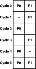
This instruction-pairing takes six cycles to execute eight instructions. The first pair of instructions issues in parallel, but the next four can’t because P1 instructions precede a P0 instructions. The last two issue in parallel.
Oddly enough, the performance of this example can be improved by inserting instructions: nop and lnop. These instructions don’t do anything, but nop is P0 and lnop is P1. By inserting nops, you can make sure that a P0 instruction precedes every P1 instruction, as shown in Figure 15.5.
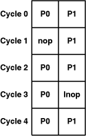
With nop and lnop, the SPU can perform dual issue with each cycle. The eight nontrivial instructions can now execute in five cycles rather than six.
There’s a lot to learn when it comes to SPU assembly: sections, directives, addressing modes, branch hints, dual-issue conditions, and hundreds of hard-to-remember opcodes. I don’t recommend building complete applications in assembly, but if you want to improve on the compiler’s output, these are the hurdles you need to leap over.
The SPU assembly instructions are similar in purpose to the intrinsics discussed in Chapter 11. If you understood the multiply high-high and rotate mask functions as intrinsics, you’ll have no problem understanding the corresponding instructions. The main difficulty is keeping track of the different types of load/store commands, branches, and immediate versus register parameters.
The Linux Application Binary Interface (ABI) specifies how information is stored in SPU registers and how the stack pointer and link register operate. The stack holds local variables, and the link register makes it possible for functions to return to their calling functions. By using the stack pointer and link register properly, you can call assembly code as a C/C++ function and call a C/C++ function from assembly code.