Finally, the fun part. Creating 3D graphics is gratifying, but it doesn’t compare to the sense of accomplishment that comes from building an immersive, 3D, full-featured game. You’re not just designing figures, you’re creating a world! I’ve heard it time and again: Regular programming is a job, game programming is an obsession.
Ogre3D, hereafter referred to as Ogre, is an open source game development toolset that, in the right hands, can build games with all the features expected from professional offerings. Sound, animation, textures, shadows, skeletons—if it’s not in Ogre, it probably isn’t that important. And if it’s not in Ogre and it is important, you can extend Ogre’s capabilities with plug-ins.
This chapter can’t do much more that scratch the surface of Ogre’s features. However, it does provide enough of a background to create a ninja who kicks, flips, crouches, and jumps.
Ogre (Object-Oriented Graphics Rendering Engine) is a rich toolset with many, many features. Rather than start with the detailed theory, this section shows you how to build and run your first Ogre application. But first, you need to obtain and compile the Ogre source code.
Note
Ogre needs access to the OpenGL libraries created in Chapter 20, “OpenGL on the Cell: Gallium and Mesa.” There are a number of ways to enable this: Add the library directory to /etc/ld.so.conf and enter ldconfig, enter export LD_LIBRARY_PATH with the name of the library directory, or permanently modify LD_LIBRARY_PATH in ~/bash_profile.
At the time of this writing, four packages need to be installed to build Ogre applications on the Cell: OIS, zziplib, FreeImage, and Ogre itself. The first dependencies are OIS, the Object-Oriented Input System, and zziplib, a library that extracts data from zip archives. Install these dependencies with the following command:
yum install ois ois-devel zziplib zziplib-devel
Installing the next two dependencies, FreeImage and Ogre, is more involved. In both cases, the source code has to be downloaded and compiled.
FreeImage is a set of tools that enable you to manipulate common image formats such as JPEGs, TIFFs, and bitmaps. Ogre needs these tools to process textures, so go to the FreeImage hosting site, http://freeimage.sourceforge.net. Click the Download link on the left, find the heading entitled Source distribution, and click the Download FreeImage link.
When you unzip the archive, the top-level FreeImage directory contains files for many different operating systems besides Linux. Don’t be concerned. Change to the FreeImage directory and run
make
and
make install
This builds the FreeImage libraries and places them in your system library path.
The last download is the Ogre source code itself. Log in to the Ogre CVS repository with the following command:
cvs -d:pserver:anonymous/cvsroot/ogre login
Press Enter when it asks for a password. Then download the source code with the following command:
cvs -z3 -d:pserver:anonymous/cvsroot/ogre co -P ogrenew
This downloads the source code into a directory called ogrenew. To build the source code into libraries, change to the ogrenew directory and enter the following commands:
./bootstrap
./configure --disable-cg
make
make install
The —disable-cg flag tells Ogre that NVidia’s Cg Toolkit will not be available for the build. Ogre’s example applications require this toolkit, but it’s currently unavailable for the Cell processor.
It takes some time to build Ogre, but when it completes, you’ll have a series of new libraries in your file system. In /usr/local/lib, you’ll find libOgreMain and a subdirectory called OGRE. The /usr/local/lib/OGRE directory holds four shared libraries: Plugin_BSPSceneManager, Plugin_OctreeSceneManager, Plugin_ParticleFX, and RenderSystem_GL. If all these libraries are present, the Ogre framework is installed and you’re ready to start building applications.
The Chapter21/ogre_basic directory contains three files: ogre_basic.cpp, plugins.cfg, and Makefile. Open Makefile and identify the location of the Ogre home directory. Then run make at the command line. A dialog should appear that looks similar to Figure 21.1.
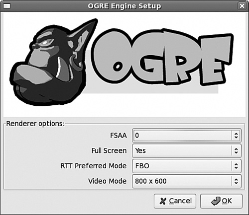
This configuration dialog identifies four parameters required by the Ogre application:
FSAA—. Full-Scene Anti-Aliasing. This isn’t supported on the Cell (yet), so leave this at 0.
Full Screen—. Whether the application should take up the entire screen. Set this to No.
RTT Preferred Mode—. Render To Texture. This setting determines how pixel data is managed in textures. Leave this set to FBO (Framebuffer Object)
Video Mode—. Set this to a suitable resolution for your display.
After you’ve entered the settings, click OK. A green window will appear with the title Ogre Basic. It’s not much of a game, but it’s a start.
Look at the two new files inside the ogre_basic directory: ogre.cfg and Ogre.log. The first file contains the configuration settings from the Setup dialog, such as the display mode and screen usage. Now that this file exists, the dialog won’t appear when you start the application.
The second file, Ogre.log, maintains a running account of Ogre’s operation as the application executes. If you look at this file, you’ll see the bewildering array of C++ objects that were combined to create the green window. The next section examines a number of these objects in detail.
The ogre_basic application performs three simple operations:
Create a
Rootobject and aRenderWindowDefine the viewing region with the
SceneManagerandCameraConfigure the window with the
Viewportobject
Listing 21.1 presents the code that implements each of these steps.
Example 21.1. Introduction to Ogre: ogre_basic.cpp
#include <Ogre.h>

using namespace Ogre;
using namespace std;

int main(int, char **) {

   /* Create Root and RenderWindow */
   Root *root = new Root("./plugins.cfg");
   if (!root->restoreConfig()) {
      if (!root->showConfigDialog()) {
         return 1;
      }
   }
   RenderWindow *window =
      root->initialise(true, "Ogre Basic");

   /* Create Scene Manager and Camera */
   SceneManager* sceneManager =
      root->createSceneManager(ST_GENERIC, "SceneManager");
   Camera* camera = sceneManager->createCamera("Camera");
   camera->setPosition(Vector3(0.0f, 0.0f, 500.0f));
   camera->lookAt(Vector3(0.0f, 0.0f, 0.0f));
   camera->setNearClipDistance(5.0f);
   camera->setFarClipDistance(1000.0f);

   /* Bind scene and RenderWindow */
   Viewport *viewport = window->addViewport(camera);
   viewport->setBackgroundColour(ColourValue(0.0f, 1.0f, 0.0f));
   camera->setAspectRatio(Real(viewport->getActualWidth()) /
                          Real(viewport->getActualHeight()));

   /* Run the main loop and dispose of the root at finish */
   root->startRendering();
   delete root;
   return 0;
}
There are five fundamental structures in this code: the Root, RenderWindow, SceneManager, Camera, and Viewport. This section briefly explains each object’s purpose and function.
All the objects in an Ogre application are directly or indirectly created by a Root, so this is the first object that must be constructed. Its full constructor is given by the following signature:
Root(const String& pluginFile, const String& settingsFile, const String& logFile)
pluginFile is the file identifying the application’s plug-ins (default: plugins.cfg), settingsFile is the file containing the configuration settings (default: ogre.cfg), and logFile is the file that holds execution details (default: Ogre.log). If any of the parameters aren’t identified, the default value is used.
Ogre makes few hard-coded requirements as to how its underlying capabilities are implemented. For example, Ogre applications need to render graphics, but Ogre accepts multiple rendering systems, such as OpenGL and Direct3D. Implementation details are provided by plug-ins, which are essentially dynamic libraries with specific interfaces. This presentation doesn’t explain how plug-ins are created, but it does describe the plug-ins needed for the example code.
OpenGL is available for the Cell, but the Cg Tookit is not. For this reason, the example plug-in configuration file, plugins.cfg, includes the RenderSystem_GL.so plug-in but leaves out the Plugin_CgProgramManager plug-in. This is presented in Listing 21.2.
Example 21.2. Ogre Plug-in Listing: plugins.cfg
# Defines plug-ins to load

# Define plug-in folder
PluginFolder=/usr/local/lib/OGRE

# Define OpenGL rendering implementation plug-in
Plugin=RenderSystem_GL.so
Plugin=Plugin_ParticleFX.so
Plugin=Plugin_BSPSceneManager.so
Plugin=Plugin_OctreeSceneManager.so
This configuration file identifies where the plug-ins are located and which plug-ins are available. By default, the Ogre installation places the libraries in /usr/local/lib/OGRE.
The plugins.cfg file, like all Ogre configuration files, defines properties with name=value pairs. The four basic plug-ins are as follows:
RenderSystem_GL.so—. Allows Ogre to render graphics using OpenGL libraries
Plugin_ParticleFX.so—. Provides the application with a particle system processor
Plugin_BSPSceneManager.so—. Manages the viewing region with binary-space partitioning
Plugin_OctreeSceneManager.so—. Partitions space with octrees
The operation of the Ogre particle system lies beyond the scope of this discussion, and the binary-space partitioning plug-in is rarely used.
In addition to the constructor, the Root class contains four functions that manage plug-ins at runtime, as follows:
loadPlugins(const String& pluginFile): Instantiates plug-ins from a plug-in configuration fileinitialisePlugins(): Allow plug-ins to operate after the renderer is createdshutdownPlugins(): End operation of loaded plug-insunloadPlugins(): Unload all loaded plug-ins
Note two points. First, plug-ins are not accessed directly, but are loaded/unloaded according to the configuration file. This ensures that Ogre can process plug-ins independently of the plug-in file format. Second, Ogre functions and classes are spelled in the British/Canadian manner, so it’s initialise rather than initialize and colour instead of color.
Besides reading in plug-ins, the Root object creates the objects that manage the game’s operation. In Listing 21.1, the Root creates a RenderWindow and a SceneManager. Then, after the window and manager are configured, it renders the application’s graphics. These are the primary responsibilities of the Root, and Table 21.1 lists a number of the functions used to perform them.
Table 21.1. Ogre Root Functions
Description | |
|---|---|
| Check for an existing file containing configuration settings. |
| Save configuration parameters to a file. |
| Create dialog box to receive settings from the user. |
| Return a |
| Make a |
| Start Ogre application. If |
| Return whether the |
| Create a |
| Return a |
| Retrieve information about a |
| Destroy the existing |
| Draw a single frame in the |
| Draw repeated frames in the |
The first three functions are concerned with Ogre’s configuration settings. In ogre_basic.cpp, the first thing the Root does once it’s constructed is call restoreConfig to check whether settings can be found. If the file’s name isn’t identified in the constructor, it looks for a file named ogre.cfg. If the function returns false, the Root creates the configuration dialog (Figure 21.1) with showConfigDialog.
If you look at the configuration settings file generated by the dialog, ogre.cfg, you’ll see that the first line identifies the rendering system:
Render System=OpenGL Rendering Subsystem
This is the most important of the Ogre configuration settings, and is determined automatically as the configuration dialog is created. However, the rendering method can also be set at runtime. First, Root calls getAvailableRenderers to obtain a RenderSystemList. After checking the list, it finds a suitable RenderSystem and makes one active with setRenderSystem.
After a RenderSystem is chosen, the application can be initialized. The goal of the initialization process is to create a RenderWindow that will use the selected RenderSystem to draw its graphics. The code in Listing 21.1 calls the initialise function for this purpose. The first argument identifies whether a RenderWindow should be created automatically. If so, the next arguments configure its appearance. Alternatively, a RenderWindow can be created with createRenderWindow.
The next three functions in Table 21.1 create and configure the SceneManager. This object organizes the viewing region and any graphics inside this region. The Root functions for dealing with this manager are straightforward, and a great deal of this chapter discusses the operation of the SceneManager in greater depth.
The last two functions perform the actual graphical rendering. The first, renderOneFrame, accesses all the Ogre resources to present the pixels inside the window for a single frame. The example code uses the second function, startRendering, which invokes renderOneFrame in an infinite loop.
This loop is important to understand in case you need to customize Ogre’s rendering process. For example, if you need to insert Ogre’s functionality inside another application or insert another application inside Ogre, you can create a custom processing loop using Ogre’s renderOneFrame function.
The Root object initializes the application, but the SceneManager controls how its graphics are presented. This class has hundreds upon hundreds of functions, and much of this chapter is concerned with how they work together to manage Ogre scenes. Only one SceneManager function is used in Listing 21.1. SceneManager::createCamera returns a Camera object.
Chapter 20 explained how OpenGL positions the viewer with gluLookAt and defines viewing regions with glFrustum and gluPerspective. In Ogre, the Camera object serves both purposes. Table 21.2 lists a number of Camera functions that make this possible.
Table 21.2. Ogre Camera Functions
Description | |
|---|---|
| Places the viewer inside the viewing region |
| Point the viewer in the given direction |
| Set the field of view in the y-direction |
| Define the width-to-height ratio of the viewing region |
| Set the position of the near face of the viewing region |
| Set the position of the far face of the viewing region |
| Translate the camera’s position by |
| Rotate the camera around the z-axis |
| Rotate the camera around the x-axis |
| Rotate the camera around the y-axis |
The first two functions identify where the viewer is located and the viewing direction. Both accept a Vector3 datatype, which contains three Real values. The C/C++ datatype represented by Real can be a float or a double, as defined by the following code in OgrePrerequisites.h:
if OGRE_DOUBLE_PRECISION == 1
    typedef double Real;
#else
    typedef float Real;
#endif
The next four functions define the application’s viewing region, and their names closely resemble the arguments of the gluPerspective function in OpenGL. The first, setFOVy, specifies the field of view in the y-direction depending on a Radian value, which is essentially the same as a Real. setAspectRatio defines the width-to-height ratio of the viewing region, and setNearClipDistance and setFarClipDistance define the coordinates of the front and back faces of the viewing region.
The last four functions move the Camera at runtime. move translates the Camera’s position, and roll, pitch, and yaw rotate the Camera through an angle. roll rotates around the z-axis, pitch rotates around the x-axis, and yaw rotates the Camera around the y-axis.
After the Camera is configured, it has to be bound to the RenderWindow. This binding is made possible by a Viewport object. Each Viewport has a single Camera, but one Camera may have multiple Viewports with different parameters. This makes it possible to include close-ups and picture-in-picture effects within a single window.
A Viewport provides the window’s actual dimensions with getActualWidth and getActualHeight and the window’s location with getActualLeft and getActualTop. It can be configured to clear itself after each frame and can be enabled to display skies or overlays.
The example in Listing 21.1 creates the window and viewing region, but an important question remains: How do you put objects in the viewing region? The answer is more complicated with Ogre than it is with OpenGL. The process of placing an object into the viewing region consists of two main tasks:
This section discusses the first task, which deals with Ogre resources. To Ogre, a resource is anything needed to render objects, including fonts, textures, and routines directed to the GPU. Resources can be constructed in code, but in most instances, each resource corresponds to a file.
Three particular resources are explored: meshes, which define an object’s shape; skeletons, which define how a mesh moves; and materials, which define what an object looks like. In each case, we’ll be looking at the resource data for a ninja graphic. After describing these resources, this discussion explains how they’re accessed in code with a ResourceManager.
Unlike OpenGL, Ogre objects aren’t created with individual vertex commands. Instead, developers create models with professional tools such as Blender and Maya. Then they convert these models into resources that Ogre applications can access. Ogre provides many conversion tools for this purpose, and they can be found in the ogrenew/Tools directory.
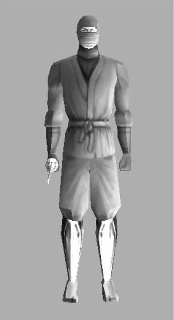
The resource that defines an object’s vertices is a binary mesh file, *.mesh. The example application in this chapter won’t build a mesh from scratch, but will instead use a sample mesh from the ogrenew/Samples directory. I recommend that you explore this directory to see all the samples that Ogre has to offer. To whet your appetite, Figure 21.2 shows what the ninja in the ninja.mesh file looks like when combined with its material.
Meshes are binary files and there’s no direct way to read the information they contain. However, in the ogrenew/Tools/XMLConverter/src directory, you’ll find an executable called OgreXMLConverter. This helpful tool creates an XML representation of the data inside a mesh. Change into this directory and enter the following command:
./OgreXMLConverter ../../../Samples/Media/models/ninja.mesh ninja_mesh.xml
This creates a large XML file (ninja_mesh.xml) whose top-level element is <mesh>. The information contained in the mesh file is summarized in the following code:
<mesh>

   <submesh>
      <faces>
         (list of 904 triangles made up of 781 vertices)
      </faces>
      <geometry>
         <vertexbuffer>
            (list of 781 vertices with positions and normals)
         </vertexbuffer>
         <vertexbuffer>
            (texture coordinates for each vertex)
         </vertexbuffer>
      </geometry>
      <boneassignments>
         (matches vertices to bones and identifies weight)
      </boneassignments>
   </submesh>

   <submesh>
      <faces>
         (list of 104 triangles made up of 61 vertices)
      </faces>
      <geometry>
         <vertexbuffer>
            (list of 61 vertices with positions and normals)
         </vertexbuffer>
         <vertexbuffer>
            (texture coordinates for each vertex)
         </vertexbuffer>
      </geometry>
      <boneassignments>
         (matches vertices to bones and identifies weight)
      </boneassignments>
   </submesh>

   <skeletonlink name="ninja.skeleton" />

</mesh>
This provides a good idea of what meshes are and how they’re structured. A mesh is a collection of triangles whose vertices are identified with positions, normal vectors, and texture coordinates. This file consists of two submeshes: one for the ninja’s body and one for the ninja’s sword. An example triangle definition is given by the following:
<face v1="607" v2="606" v3="608" />
This states that the triangle consists of vertices 607, 606, and 608, in that order. An example vertex definition is given by the following:
<vertex>

   <position x="-5.6477" y="181.765" z="-12.0956" />
   <normal x="-0.665269" y="0.0518627" z="-0.7448" />
</vertex>
Each vertex has an index, and each vertex index is matched to a bone index. For example, the entry that matches vertex 5 to bone 17 is given by the following:
<vertexboneassignment vertexindex="5" boneindex="17" weight="1" />
It’s important to understand what data is not contained in the mesh. There is no mention of reflectance or color and no information about the model’s bones except their indices. This information is contained in additional resources. Reflectance is specified within a material resource, and each submesh identifies its material with a definition like this:
<submesh material="Examples/Ninja" usesharedvertices="false"
use32bitindexes="false" operationtype="triangle_list">
Bone structure is defined in a skeleton resource. The name of the skeleton resource is identified in the XML file by the skeletonlink element. In this example, the skeleton resource is ninja.skeleton.
When it comes to animating a graphic, you don’t want to manipulate each vertex individually. It’s much more efficient to group vertices into figures and move the figures as individual units. These figures are called bones, and the resource that defines a figure’s bones is called a skeleton. Like the mesh discussed earlier, a skeleton is represented by a file (*.skeleton) created by a modeling tool and converted for use in Ogre.
The ogrenew/Samples/Media/models directory contains a number of example skeleton files, but we’re interested in ninja.skeleton. Change to the ogrenew/Tools/XMLConverter/src directory and enter the following:
./OgreXMLConverter ../../../Samples/Media/models/ninja.skeleton ninja_skel.xml
This XML file places its data within <skeleton> elements, and its structure can be summarized as follows:
<skeleton>

   <bones>
      (list of bones, including their names, positions,
       rotation angles, and rotation axes)
   </bones>

   <bonehierarchy>
      (child bones are matched to parent bones)
   </bonehierarchy>

   <animations>
      (different ways the ninja can move)
   </animations>

</skeleton>
The 781 vertices in the ninja graphic are grouped into 28 bones, and each bone has a specific ID, name, position, rotation angle, and axis of rotation. For example, Bone12 is defined with the following entry:
<bone id="12" name="Joint13">

   <position x="0.136921" y="-6.24266" z="-3.42546" />

   <rotation angle="0">
      <axis x="1" y="0" z="0" />
   </rotation>

</bone>
No bone moves independently, and each bone movement can be represented as a rotation relative to a parent bone. The connection of a bone to its parent is called a joint. The position field identifies the location of the joint, and the axis field identifies the axis around which the bone rotates. In this case, the bone is connected at position (0.136921, −6.24266, −3.42546) and rotates around the x-axis. Its initial angle is 0 radians. No angular limits are placed on bone rotation, so the ninja’s head could theoretically swivel all the way around (only possible for ninjas, of course).
For each child bone, the skeleton file identifies the parent bone that constrains its motion in space. That is, when a parent bone moves, each of its children must move by the same amount in the same direction. The child-parent relationships are placed within the <bonehierarchy></bonehierarchy> tags, and an example is given by the following:
<boneparent bone="Joint10" parent="Joint9" />
The rest of the information in the skeleton file defines how the ninja’s bones move together to perform a single action. This information is identified within <animations></animations> tags, and ninja.skeleton identifies 20 different animations with names such as Backflip, Crouch, and Jump. These encompass all the ways the ninja can move within a game.
The concepts behind Ogre animation are simple to understand but the terminology can be confusing. The fundamental data structures are animations, tracks, and keyframes:
Keyframe—. Defines the movement (translation and rotation) of one bone over a single time interval.
Track—. Defines the movement of one bone throughout the entire animation. A track consists of multiple keyframes, with one keyframe for each time interval in the animation.
Animation—. Defines the movement of every bone in the skeleton over a series of time intervals. Each animation consists of a series of tracks, with one track for each bone that moves during the course of the animation.
An example will clarify these relationships. One of the animations in ninja_skel.xml is called SideKick, and each bone has a separate track. The animation lasts for .5833 seconds, and the following lines show how the bone named Joint13 moves during this interval:
<track bone="Joint13">
   <keyframes>

      <keyframe time="0">
         <translate x="0" y="0" z="0" />
         <rotate angle="0">
            <axis x="1" y="0" z="0" />
         </rotate>
      </keyframe>

      <keyframe time="0.25">
         <translate x="0" y="0" z="0" />
         <rotate angle="0.139626">
            <axis x="-0.525351" y="-0.850408" z="-0.028489" />
         </rotate>
      </keyframe>

      <keyframe time="0.333333">
         <translate x="0" y="0" z="0" />
         <rotate angle="0.139626">
            <axis x="-0.525351" y="-0.850408" z="-0.028489" />
         </rotate>
      </keyframe>

      <keyframe time="0.583333">
         <translate x="0" y="0" z="0" />
         <rotate angle="0">
            <axis x="1" y="0" z="0" />
         </rotate>
      </keyframe>

   </keyframes>
</track>
In this case, the bone rotates 0.139626 radians by time 0.25, remains in this position until 0.333 seconds, and returns to its original position at time 0.5833. Time intervals vary from track to track, and other bones move five or six times during the animation. Remember that this rotation is performed relative to the parent bone.
An Ogre material resource defines how submeshes are rendered. This information includes properties like texture, luster, reflectance, and background color. Material data is usually contained in a *.material file, but this isn’t a binary file like *.mesh or *.skeleton. Ogre material resources are text files that define material properties using a customized scripting language.
A *.material file may define properties of multiple submeshes, and each definition consists of the same essential elements:
Pass—. A single rendering of the submesh. Contains attributes,
texture_unitdefinitions, vertex programs, and fragment programs.Technique—. A method of rendering an submesh. Contains one or more passes.
Material—. The complete rendering instructions for a submesh. May contain multiple techniques to support different rendering hardware or software.
These elements are nested inside the *.material script file using the following format:
material material_name {

   technique technique_name1 {

      pass pass_name {
         attribute_name attribute_data

         texture_unit {
            texture_attribute texture_data
            texture_attribute texture_data
         }
      }

   technique technique_name2 {

      pass pass_name {
         attribute_name attribute_data
      }

   }
}
The names of the pass and technique elements are optional, but each material definition must have a unique name. This is the identifier used in a mesh file’s submesh definition. The submesh elements in ninja.mesh are rendered using a material called Examples/Ninja.
The script file containing the ninja material is Example.material, located in ogrenew/Samples/Media/materials/scripts. The ninja entry, Examples/Ninja, is very simple:
material Examples/Ninja {
   technique {
      pass {
         texture_unit {
            texture nskingr.jpg
         }
      }
   }
}
The nskingr.jpg image file contains a series of 2D clips that need to be mapped to vertices of the ninja and sword. In this case, the material definition is simple, but the actual application is difficult.
The example in this chapter takes a different approach: Rather than apply 2D textures, we’ll characterize the ninja’s appearance by creating a material script and setting our own pass attributes. Table 21.3 identifies the different attributes available for customizing parameters inside a pass definition. Each attribute is followed by one or more arguments: italicized arguments require values and arguments in boldface represent default values.
Table 21.3. Material Pass Attributes
Attribute | Description |
|---|---|
| Whether dynamic lighting is available |
| Maximum number of light objects to be processed for pass |
| Offset of the first light to be processed |
| The type of shading that should be used for light processing |
| How much environmental light is reflected |
| How much light from a |
| How much highlighting from a |
| The material’s glow color |
| Whether triangle processing should be limited to the clipping volume representing the lit region |
| Whether rendering should be limited to the scissor rectangle representing the lit region |
| Manner in which the pass blends with existing scene |
| Blend operations between existing and upcoming scenes |
| Number of times the pass will be processed per call |
| Whether pass requires depth checking |
| Method used to compare depth values |
| Modifies the depth value associated with the pass |
| Multiplies depth value with each iteration |
| How alpha values will reject pixels from rendering |
| Whether |
| Whether normal vectors should be renormalized with each pass (length set to 1) |
| How hardware should distinguish backward-facing polygons from forward-facing polygons |
| How software should distinguish backward-facing polygons from forward-facing polygons |
| Whether polygons should be drawn as points, lines, or solids |
| Whether the |
| Enable pixel drawing |
| Whether points are attenuated with view distance or remain the same size |
| Point size in pixels or normalized coordinates with point at origin |
| The minimum point size after attenuation |
| The maximum point size after attenuation |
| Enable hardware sprite rendering |
Lighting will be discussed shortly, but a number of the topics related to these attributes (depth buffering, shading, culling, fog, and so on) lie beyond the scope of this book. Most of them, such as point_size, don’t need explanation. In many cases, the properties defined by these attributes can also be defined in code, and there are override attributes that determine which should affect the rendering.
Like most people, I prefer my ninjas to be robotic and radioactive. That is, I want the ninja (body and sword) to be dark gray, shine with high luster, and glow with an eerie green light. This preference is implemented with the ninja.material script, shown in Listing 21.2. This can be found in the Chapter21/ninja directory.
This sets the ninja to reflect dark-gray ambient light and gives it a metallic luster and a light green glow. The material’s name is ninja-material, which will be used to override the Examples/Ninja material. It’s a fine script, but before any application can access it, its file location needs to be identified in a resource configuration file.
An Ogre project needs a resource configuration file to identify the locations of meshes, skeletons, materials, and other resources. This file has the same basic structure as the plug-in configuration file, and consists of name=value statements. The difference is that value represents the path to a directory containing resource files and name provides information about how to access the files.
The only resources needed by the ninja application are ninja.mesh, ninja.skeleton, and ninja.material. The first two files are located in the ogrenew/Samples/Media/models directory and the third is located in the Chapter21/ninja project directory. Listing 21.3 presents the resource configuration file, ninja_res.cfg, accessed by the ninja application.
Example 21.3. Resource Configuration File: ninja_res.cfg
# Creates the main configuration group
[Main]

# Location of the ninja.skeleton and ninja.mesh resources
# $OGRE needs to be changed to the top-level Ogre directory
FileSystem=$OGRE/Samples/Media/models

# Location of the ninja.material resource
FileSystem=.
The FileSystem term identifies the value as being a directory. An alternative is Zip, which states that the value is a compressed (zip) file. Note that $OGRE needs to be set to the top-level Ogre directory on your system.
In code, the ninja application accesses resource files through a ConfigFile object. This object reads the configuration file and produces a SettingsMultiMap. By accessing this map, the application adds resource locations to a ResourceGroupManager. After all the locations have been read, the manager initializes the resource groups and makes the resources available throughout the application.
In the ninja.cpp code, the initResources function searches through ninja_res.cfg and adds each resource location to the ResourceGroupManager, which initializes the resources. This is shown in the following function:
void initResources() {

   /* Load resource paths from config file */
   ConfigFile cf;
   cf.load("ninja_res.cfg");

   /* Go through all sections & settings in the file */
   ConfigFile::SectionIterator seci
      = cf.getSectionIterator();
   while (seci.hasMoreElements()) {
      String secName = seci.peekNextKey();
      ConfigFile::SettingsMultiMap* settings =
         seci.getNext();
      for (ConfigFile::SettingsMultiMap::iterator i =
         settings->begin(); i != settings->end(); ++i) {

         String typeName = i->first;
         String archName = i->second;
         ResourceGroupManager::getSingleton()
            .addResourceLocation(
               archName, typeName, secName);
      }
   }
   ResourceGroupManager::getSingleton()
      .initialiseAllResourceGroups();
}
After this function is called, the application can access the graphics described in mesh files and insert them into the Ogre scene. The next section explains how this is done.
At this point, we have an Ogre window with no objects and an Ogre object with no window. This section brings them together by showing how the SceneManager places meshes inside the scene. The process consists of three tasks:
Create an
Entityto represent the mesh/skeleton/material.Create a
SceneNodethat can be managed by theSceneManager.Attach the
Entityto theSceneNodeand position it inside the viewing region.
A mesh file identifies its skeleton with the skeletonlink element and its submesh material with the material attribute. Therefore, the mesh file is the only resource the SceneManager needs to access. The SceneManager provides this access by calling createEntity, which returns a wrapper object called an Entity that represents the mesh.
For example, the following code creates an Entity named newEntity from ninja.mesh:
Entity ninjaEntity = sceneManager->createEntity("newEntity", "ninja.mesh");An Entity object provides details related to an object’s mesh, skeleton, and material. For example, Entity::getSkeleton() returns a SkeletonInstance that contains skeleton data. Entity::getMesh() returns a pointer to a Mesh object.
Just as an Entity represents a mesh, a submesh is represented by a SubEntity. As you’ll recall, ninja.mesh defines two submeshes: one for the ninja’s body and one for the sword. Both submeshes are associated with the Ninja/Examples material, but the following two lines override this association:
ninjaEntity->getSubEntity(0)->setMaterialName("ninja-material");
ninjaEntity->getSubEntity(1)->setMaterialName("ninja-material");
This forces the body/sword submeshes to be rendered according to the ninja-material material defined in Listing 21.2.
The Entity provides access to many details about an object, but not its position. Before an Entity can be inserted into a viewing region, the Entity has to be attached to a node.
The SceneManager serves many roles, but it derives its name from the fact that it positions moveable objects inside the viewing region, or scene. The term moveable object refers to more than just meshes; it includes background scenery, particle systems, and the viewing camera. The SceneManager doesn’t pay attention to the different types of objects, but manages them as abstract objects called SceneNodes.
A SceneNode has no size, shape, or color. Instead, it serves as a “hook” into the scene to which moveable objects can be attached. When this attachment is made, the node and its corresponding object can be positioned in the scene, translated, scaled, and oriented. Table 21.4 lists many of the SceneNode functions that make this possible.
Table 21.4. Functions of the SceneNode Class
Function | Description |
|---|---|
| Associate the |
| Remove the association between the object and the node |
| Create a child node with the given location and orientation |
| Add an existing node as a child node |
| Return the node object corresponding to the index |
| Return a |
| Remove the child with the given index from the list of children |
| Remove the child with the given index from the list of children and deallocate its memory |
| Place the node inside the viewing region |
| Move the node by the given vector according to the given transform space |
| Enlarge/diminish the node by the scaling factors |
| Point the node in the given direction |
| Rotate the node around the z-axis |
| Rotate the node around the x-axis |
| Rotate the node around the y-axis |
The first two functions are concerned with associations between the SceneNode and a MoveableObject, which includes Entity objects, Camera objects, ParticleSystem objects, and similar structures. The attachObject function creates the association, and when the SceneNode is displayed, the attached MoveableObject will take its location and orientation properties. detachObject removes the association, and the object will no longer be displayed. For example,
node->attachObject(ninjaEntity);
tells the SceneManager to display ninjaEntity according to the properties set for node.
In addition to having associations with MoveableObjects, nodes also associate with one another. These relationships follow a traditional parent-child structure, and the relationships are created using two functions: createChild and addChild. The first creates a new child node with the given coordinates and orientation. The second adds an existing node to the parent’s list of children. getChild accesses child nodes by name or numeric index, and getChildIterator returns a ChildNodeIterator that can cycle through each of them.
Parent-child relationships between nodes are important for two reasons. First, the parents and children form a node tree that can be easily searched when the user selects nodes in a region. Second, if either the parent or child is moved, the following rules are observed:
When a parent node is transformed (translated, rotated, and so on), all its child nodes undergo the same transformation.
When a child node is transformed, the coordinates of the transformation are, by default, relative to the parent node.
This is important to understand. If a parent node’s actual location is (a, b, c) and a child node calls setPosition(x, y, z), its new position in the scene will be (a + x, b + y, c + z). The situation is different for the translate function. This accepts a second argument that identifies a TransformState. This can take one of three values:
TS_LOCAL: The transform is relative to the object’s local coordinate system.TS_PARENT: The transform is relative to the parent’s coordinates.TS_WORLD: The transform is relative to the scene’s coordinates.
Like any search tree, the tree of SceneNodes has a root node that serves as the foremost ancestor. This is created by the SceneManager and can be accessed with SceneManager::getRootSceneNode(). This sets the coordinate system for all of the nodes in the scene, and for this reason the root node can be thought of as the scene’s origin.
The node tree for our ninja scene is particularly simple. The SceneManager creates a root node and the root node creates a node for the ninja. Then the ninjaNode attaches the ninjaEntity. This is shown with the following code:
Entity *ninjaEntity =
   sceneManager->createEntity("ninja", "ninja.mesh");

SceneNode* ninjaNode =
   sceneManager->getRootSceneNode()->
      createChildSceneNode("NinjaNode");

ninjaNode->attachObject(ninjaEntity);
In this case, the ninjaNode remains at the origin. To move or rotate the object, use ninjaNode->translate or ninjaNode->setOrientation.
Meshes aren’t the only objects that can be associated with SceneNodes. Lighting is a very important aspect of any graphical application, and objects of the Light class can be attached to nodes and positioned just as easily as if they were meshes.
The SceneManager handles lighting in two ways: It has its own function (setAmbientLight) that defines the general lighting in the scene. It also provides functions that manage Light objects, such as createLight, getLight, and destroyLight. Our example application uses both methods.
A Light object encapsulates the position, color, and nature of a light in the scene. This is a MoveableObject and can be attached to SceneNodes. Table 21.5 lists a number of important functions contained in the Light class.
Table 21.5. Functions of the Light Class
Function | Description |
|---|---|
| Place the |
| Point the |
| Set whether the light is a point, directional, or spotlight |
| Return the |
| Specify how the illumination diminishes in space |
| Specify the component of the light that reflects in all directions |
| Specify the component of the light that reflects in a particular direction |
| Select whether the light casts shadows |
The setPosition and setDirection functions are similar to those for the Camera and SceneNode. But depending on the Light’s type, this information may not be necessary. This type value is specified by Light::setType(), and it can take one of three values:
LT_POINT: Light emits from a point equally in all directions (has position, no direction).LT_DIRECTIONAL: Light emits in a single direction (has direction, no position).LT_SPOTLIGHT: Light shines in a cone (requires position and direction).
For example, a Light object of type LT_POINT doesn’t need to call setDirection. A Light of type LT_DIRECTIONAL doesn’t need to call setPosition.
The Light object has no effect on the scene’s ambient light, but controls the light’s diffuse and specular components. The diffuse component is the light reflected from an object in all directions, and its intensity is specified with setDiffuseColour. The specular component is the light that reflects in a particular direction, and is set with setSpecularColour. Both functions accept a ColourValue argument, which contains four floats between 0 and 1 representing red, green, blue, and alpha.
setAttenuation determines how the Light’s diffuse and specular components diminish as the object gets farther away from the light source. The first argument, range, sets the maximum distance at which the Light diminishes completely. The rest of the arguments, constant, linear, and quadratic, are used to compute an attenuation factor according to the equation (where d is the distance of the object from the light):
attenuation_factor = 1/(constant + linear*d + quadratic*d2)
The attenuation factor is multiplied by the Light’s intensity and is always less than 1. Directional light is not attenuated.
In the example application, the ambient lighting is set to a ColourValue of (1, 1, 1). To better depict the ninja’s metallic appearance, a Light object of type LT_POINT is configured with a diffuse component of (.5, .5, .5) and a specular component of (1, 1, 1). This configuration is accomplished with the following code:
Light* light = sceneManager->createLight("Light");

light->setType(Light::LT_POINT);

SceneNode* lightNode =
   ninjaNode->createChildSceneNode("LightNode");

lightNode->attachObject(light);

lightNode->setPosition(100.0f, 75.0f, 0.0f);
This Light object is attached to a node that is a child of the ninjaNode. This ensures that the Light’s setPosition coordinates will be relative to the ninja object.
Section 21.3, “Ogre Resources: Meshes, Skeletons, and Materials,” presented skeletons and how they combine bone movements into animation routines. This section explores this further and describes how animation routines can be executed in code. This code tells the ninja to jump, attack, spin, and kick.
Rather than have the ninja execute movements in a loop, it would be more game-like if the graphic responded to keystrokes. For this reason, the first topic of this section involves the OIS capabilities for reading user input.
Note
The PlayStation 3 does not process OIS calls properly, so the lines of ninja.cpp involving keyboards and listeners have been commented out. The uncommented application will execute correctly on a different Linux system.
Ogre applications rely on the Object-Oriented Input System, or OIS, to read and respond to user-generated events. This important package is easy to understand, and the ninja application only requires two OIS classes: InputManager and Keyboard.
InputManager is the central class of OIS. Its purpose is to build input objects that receive input data from the user. Examples of input objects include Keyboard, Mouse, and Joystick objects. The Keyboard class contains two important functions:
void capture():Saves the current keyboard statebool isKeyDown(KeyCode key):Checks to see whether a specific key was pressed
The first function stores the keyboard’s state and the second function checks whether a key corresponding to a KeyCode was pressed. For example, the following line accesses the keyboard object to determine whether its backslash character () was pressed:
if (keyboard->isKeyDown(OIS::KC_BACKSLASH)) {}There is no way to directly determine which key was pressed, so a long if..else statement may be needed to respond to different keys.
Animating a mesh is simple if its skeleton already identifies its keyframes, tracks, and animations. The Entity::getAnimationState function accepts the name of an animation and returns a pointer to an AnimationState object. For example, our application accesses the Kick animation with the following line:
AnimationState* state = ninja->getAnimationState("Kick");When the animation state is available, the application can configure and start the animation. Four important functions are as follows:
AnimationState::setEnabled(bool): Enable the animation to runAnimationState::setTimePosition(Real time): Position the animation at the specified timeAnimationState::addTime(Real time): Addtimeto the state’s internal time counterAnimationState::setLoop(bool): Set the animation to run in a loop
There is no run or start function for the animation; the mesh position is determined by the AnimationState’s time value. The time value of each AnimationState begins at 0.0s, and if this doesn’t change, the mesh remains in its initial position. When the time is changed with setTimePosition or addTime, the mesh moves in a manner defined in the skeleton file.
Each animation has a completion time: the number of seconds needed to run the animation from start to finish. This is identified in the skeleton file, and the following definition in ninja.skeleton states that the Kick animation finishes in 0.83333 seconds:
<animation name="Kick" length="0.833333">
If setLoop is set to true, the mesh continues to move when the time increases past its completion time. If setLoop is set to false, the mesh does not move past its completion time.
An important question arises: How does an application generate time values to update the animation state? A function such as gettimeofday might work, but it’s inefficient and unnecessary. It’s a better idea to monitor the time between frames, and as each new frame is rendered, increase the animation state time by the time since the last frame. Ogre’s FrameListener class makes this possible.
When a FrameListener is added to an application, its functions will be called as each new frame is rendered. These functions are as follows:
frameStarted(const FrameEvent &event): Called as each new frame is begunframeRenderingQueued(const FrameEvent &event): Called after rendering commands are issued to the rendererframeEnded(const FrameEvent &event): Called after the frame has finished rendering
Each function receives a FrameEvent that provides information about the application’s timing. The class contains two fields: timeSinceLastEvent provides the elapsed time since an event was fired and timeSinceLastFrame provides the number of seconds since the last frame was rendered.
In the example application, the NinjaListener class extends FrameListener. As each new frame starts rendering, the NinjaListener performs three tasks. It captures keyboard input with keyboard->capture(), changes the animation state depending on the keystroke, and increments the animation state’s time by the time since the last frame. These actions are implemented within the frameStarted function, presented as follows.
bool NinjaListener::frameStarted(const FrameEvent& evt) {
   keyboard->capture();

   if (keyboard->isKeyDown(OIS::KC_0))
      state = ninja->getAnimationState("Kick");
   else if (keyboard->isKeyDown(OIS::KC_1))
      state = ninja->getAnimationState("Crouch");
   else if (keyboard->isKeyDown(OIS::KC_2))
      state = ninja->getAnimationState("Attack1");
   else if (keyboard->isKeyDown(OIS::KC_3))
      state = ninja->getAnimationState("HighJump");
   else if (keyboard->isKeyDown(OIS::KC_4))
      state = ninja->getAnimationState("SideKick");
   else if (keyboard->isKeyDown(OIS::KC_5))
      state = ninja->getAnimationState("Attack2");
   else if (keyboard->isKeyDown(OIS::KC_6))
      state = ninja->getAnimationState("Spin");
   else if (keyboard->isKeyDown(OIS::KC_7))
      state = ninja->getAnimationState("Backflip");
   else if (keyboard->isKeyDown(OIS::KC_8))
      state = ninja->getAnimationState("Block");
   else if (keyboard->isKeyDown(OIS::KC_9))
      state = ninja->getAnimationState("Attack3");

   state->addTime(evt.timeSinceLastFrame);
   return true;
}
When you run the ninja executable, the figure will start with Attack3 because this was the last value of the animation state. You can change the animation by entering keystrokes between 0 and 9. Figure 21.3 shows two scenes depicting the ninja’s movement.

Most of the ninja.cpp source code has been presented in pieces, but there are a few points worth mentioning. The ninja is located at the origin and faces in the negative z-direction. Therefore, the camera has a z-value of −600 and looks in the positive z-direction. The left side of the ninja shines brighter than the rest of the object because of the point light and the ninja’s high specular reflectivity.
It takes time to develop fluency with Ogre, but the capabilities are astounding. It’s no surprise that many professional game developers rely on Ogre rather than a proprietary engine. Both Buka Entertainment’s Pacific Storm and Deka 13’s Ankh were developed with Ogre.
The basic Ogre classes are simple to understand. The Root represents the application itself, and serves three important purposes: It accesses the application’s plug-ins, creates the objects that make up the application, and performs the rendering process. The SceneManager creates the Camera and manages nodes inside the viewing region.
The scene nodes make it possible for moveable objects to appear in the scene. The Entity object represents a mesh, which defines the vertices of an object. The object’s vertices are grouped into bones, which move as individual units. The skeleton file shows how the bones move within animations, and the material file definews the object’s rendering parameters, such as its reflectance and texturing. Meshes and skeletons are commonly incorporated inside files created with external modeling tools.
Ogre receives user input using the capabilities provided by the Object-Oriented Input System, or OIS. In the example application, an OIS::Keyboard object selects the ninja’s animation state. Then, as each frame starts, the NinjaListener adds the rendering time to the current animation state. This changing time causes the skeleton bones to move, and they continue to move in a loop until a new animation state is selected.
There’s a great deal more to Ogre than the topics presented in this chapter. Besides special effects like fog, shadows, and shading, there are also particle systems, overlays, and vertex animation, or morphing. I encourage you to read the fine Ogre manual and explore these capabilities on your own.