Previous chapters discussed how to build, debug, and simulate applications using the SDK. This chapter gets inside the Cell and looks at what happens as an executable runs. It focuses on the PPU’s structure, instruction pipeline, and memory management. As the discussion progresses, example code is provided to show how you can take advantage of the PPU’s internal resources in your applications.
It’s important to note that this presentation is concerned only with applications running in user mode. That is, it doesn’t discuss privileged resources or the process of building an operating system to run on the PPU. OS development is a vast topic, and even a cursory treatment would require an entire book. This chapter also doesn’t describe the Cell’s hypervisor capability, which allows one OS to run under the guidance of a second. For example, if you’re running Linux on a PlayStation 3, the Linux OS is supervised by Sony’s proprietary operating system, GameOS.
This and the following chapters assume that your applications are running under an existing operating system. It’s further assumed that the OS is Linux.
The PPU supports the PowerPC and AltiVec instruction sets, so you can write code in any language that compiles to these low-level instructions. The SDK’s tools and libraries were created with C/C++ development in mind, so this book is going to concentrate on these languages. This chapter focuses on controlling the PPU’s operation through code, and Chapter 8, “SIMD Programming on the PPU, Part 1: Vector Libraries and Functions,” covers SIMD coding with AltiVec.
But first, it’s important to understand the basics of PPU development: datatypes, bit ordering, libraries, and intrinsic functions.
Table 6.1 lists the fundamental datatypes supported by the PPU, and they should look familiar. Advanced datatypes, such as _Complex, are declared in additional code libraries.
Table 6.1. Fundamental PPU Datatypes (Not all Are Available on the SPU)
Datatype | Content | Size |
|---|---|---|
| True/False | 1 byte |
| ASCII character/integer (−128 to 127) | 1 byte |
| Integer (0 to 255) | 1 byte |
| Short integer (−32,768 to 32,767) | 2 bytes |
| Short integer (0 to 65,535) | 2 bytes |
| Wide character | 2 bytes |
| Integer (−2,147,483,648 to 2,147,483,647) | 4 bytes |
| Integer (0 to 4,294,967,295) | 4 bytes |
| Single-precision floating-point value | 4 bytes |
| Double-precision floating-point value | 8 bytes |
| Integer (−9,223,372,036,854,775,808 to 9,223,372,036,854,775,807) | 8 bytes |
| Integer (0 to 18,446,744,073,709,551,615) | 8 bytes |
Note
AltiVec also provides a series of vector datatypes that hold multiple chars, shorts, ints, and floats in 128-bit structures. These vector types and the functions that manipulate them are discussed in Chapter 8.
By default, each variable is aligned at a boundary corresponding to its datatype size. For example, a variable occupying four bytes, such as an int, will be stored at a 4-byte boundary. This means that its memory location must be divisible by four: 0x0FFFFFFC is an valid int address, but not 0x0FFFFFF7 or 0x0FFFFFFA or 0xFFFFFFD. Similarly, single-byte variables are byte-aligned; a 2-byte variable will be placed at a 2-byte boundary, and so on.
You can control a variable’s alignment by following its declaration with the __attribute__ ((aligned (num))) intrinsic, where num represents the alignment size. For example, you can force an int (4 bytes) to be aligned on a doubleword (8 bytes) boundary with the declaration:
int var __attribute__ ((aligned (8)))
Proper memory alignment becomes particularly important when transferring data between the Cell’s processing units. Interelement communication is the topic of Chapters 12, “SPU Communication, Part 1: Direct Memory Access (DMA),” and 13, “SPU Communication, Part 2: Events, Signals, and Mailboxes.”
As shown in Figure 6.1, the PPU stores all of its values in big-endian format, which means bits are considered less significant as they run from left to right. The most significant bit (MSB) is on the far left and the least-significant bit (LSB) is on the far right.
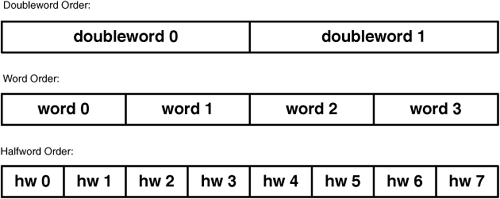
Bit ordering becomes crucial when placing values into vectors. Like the bits in a variable, the elements of a vector are numbered from left to right. This is shown in Figure 6.2, which shows how halfwords, words, and doublewords are ordered within a 128-bit wide vector.
Unlike many PowerPCs, the PPU has no little-endian mode. If you’re communicating with other processors across a network, you may have to implement your own bit-swapping routines or find a way to make the communication endian-agnostic.
When programming any processor, it’s important to know what libraries are available for coding. Thankfully, the PowerPC instruction set is sufficiently advanced that any functions you’ve used with GCC will be available for the PPU. The SDK provides the entire C Standard Library, from assert.h to time.h. It also includes all the Normative Addendum 1 (wchar.h, wctype.h, and iso646.h) and C99 libraries, whose functions are declared in complex.h, fenv.h, inttypes.h, stdint.h, tgmath.h, and stdbool.h.
There are also many libraries for communicating with the Internet (netinet, netipx, netpacket, and so on) and the Linux operating system (linux). This book won’t cover all of them, but does discuss the libraries corresponding to the following headers:
libspe2.h, pthread.h—PPU/SPU communication, covered in Chapter 7, “The SPE Runtime Management Library (
libspe)”altivec.h, simdmath.h, massv.h—PPU mathematics, covered in Chapters 8, “SIMD Programming on the PPU, Part 1: Vector Libraries and Functions,” and 9, “SIMD Programming on the PPU, Part 2: Methods and Algorithms”
elf.h—Used to manipulate ELF files, covered in Appendix A, “Understanding ELF Files”
This chapter discusses the library containing the PPU’s intrinsic functions. These are declared in the ppu_intrinsics.h header file.
The functions in ppu_intrinsics.h can be immediately and efficiently compiled into assembly. You can use them in your C/C++ code to perform low-level operations such as basic mathematics, transferring data between registers and memory, and accessing the PPU’s on-chip resources.
All the PPU’s intrinsic functions begin with two underscores and, with one exception, map to a single assembly language command. Many of the names are acronyms, such as __cntlzw(int), which stands for count leading zeroes in word. These intrinsics can be loosely divided into four categories:
Manipulating memory—Load, store, and rotate data
Numeric operations—Arithmetic and type conversion
Vector processing—Load and store vectors, conversion between scalars and vectors
Resource access—Thread control, register read and write, and cache operations
This chapter focuses on the PPU’s internal resources and their operation, so most of the sample code uses intrinsics from the last category. For example, Section 6.4, “Configuring the Pipeline,” describes the intrinsics that control threads and Section 6.5, “PPU Dual-Threaded Operation,” discusses the intrinsics that update the PPU’s L1 data cache.
One of the most useful PPU intrinsics in general-purpose coding is __mftb(), which stands for move from time base. This function accesses the PPU’s 64-bit Time Base register (TB) and stores its content as an unsigned long long. The following snippet shows how this can be used to measure the time spent executing code.
unsigned long long startTime, finishTime;
startTime = __mftb();
routine();
finishTime = __mftb();
printf("The number of elapsed ticks is %lld.
",
   finishTime - startTime);
The TB register contains the system time, measured in ticks. This register is updated by a high-frequency signal whose frequency is known by the operating system.
Note
When executed in 32-bit mode, __mftb() only returns the lower half of the TB register. In this case, you can access the upper half with __mftbu().
To relate the number of ticks to actual time, you need to find the timebase value listed in the /proc/cpuinfo file. For the PlayStation 3, this value is 79800000, meaning that there are 79.8 million ticks per second. By dividing the number of ticks in the example by 79.8, you can find out how many microseconds have elapsed in the interim. Both gettimeofday() and clock() are also available for acquiring wall time.
With so many available library functions and intrinsics, you’ll find it easy to port existing C/C++ code to the PPU. The rest of this chapter assumes you want to do more than that. It assumes you want to understand the PPU’s unique capabilities well enough to ensure that your programs run as efficiently as possible.
Put bluntly, the discussion is about to go from slightly nerdy to very nerdy. If you’d prefer to skip to the next chapter, which explains how to access SPUs in PPU code, I understand.
The PowerPC Processor Unit (PPU) is the command center of the Cell. It runs the operating system, maintains the cache, and keeps the SPUs in line. To ensure that these tasks are performed with optimal efficiency, a programmer must have a deep knowledge of how the PPU works.
This section describes the PPU from a top-level perspective. It discusses the PPU’s PowerPC lineage and the basics of its architecture, and then describes its functional units and registers.
First things first. The term PowerPC refers to a processor architecture, not a specific chip or set of chips. Since its conception in the late 1970s, IBM’s PowerPC technology has been integrated into many types of devices, from embedded systems to high-end personal computers. The PowerPC architecture is defined in standards that describe the characteristics that all PowerPC systems must have.
At the time of this writing, the most recent PowerPC standard is version 2.02, and among its many requirements are
Two modes of operation: 32-bit and 64-bit.
All values stored in big-endian fashion.
Virtual memory is divided into segments and pages, and page table entries are cached in a Transition Lookaside Buffer (TLB).
Effective addresses are 64 bits wide.
Instructions are 32 bits wide and word-aligned.
Registers are 64 bits wide, with the exception of special-purpose and memory-mapped I/O (MMIO) registers.
32 64-bit general-purpose registers (GPRs) and 32 64-bit floating-point registers (FPRs).
In 2002, IBM released the PowerPC 970 as a 64-bit processor for Apple’s next-generation Power Mac. The PPC 970 meets all the criteria set by the PowerPC 2.02 standard, and adds support for processing AltiVec instructions. These instructions perform Single Instruction, Multiple Data (SIMD) operations, which means that a single instruction can process multiple values simultaneously.
The Cell’s PPU supports the same instruction set as the PPC 970, including the full set of AltiVec instructions. Therefore, applications written for the Power Mac G5 should run on the PPU without modification. The PPU also meets the requirements of the PowerPC architecture, version 2.02, so the PPU and PowerPC 970 have many characteristics in common.
But the internal architecture of the two processors is not the same. The difference between them reflects the priorities that factored into their development. Whereas the PPC 970 was designed for performance, the PPU was designed for maximum performance-to-power and power-to-area ratios. In other words, what makes the PPU exceptional isn’t its speed, but its ability to perform as well as it does given its low operating power and small size. These qualities are vital for the Cell’s design because they make it possible to integrate multiple SPUs onto the chip.
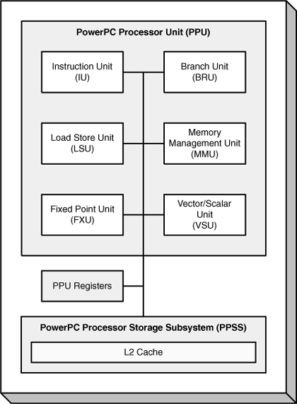
When you compare the PPU’s architecture to that of the PPC 970, one of the first things you notice is the PPU’s emphasis on simplicity. The functional units of the two processors are essentially the same, but the PPC 970 sports two load/store units, two integer units, and two floating-point units. The PPU provides only one of each. Figure 6.3 shows the PPU’s functional units and their connections to the rest of the PPE.
Their functions are listed as follows:
Instruction Unit (IU)—This unit finds the instruction addresses, determines what the instructions are, and directs the instructions to the appropriate operational unit for processing. It contains the Branch Unit (BRU), which processes branch statements, and a 32KB L1 instruction cache.
Load and Store Unit (LSU)—This unit receives requests for memory access and coordinates with the PowerPC Processor Storage Subsystem (PPSS). It contains a 32KB L1 data cache.
Vector/Scalar Unit (VSU)—This unit contains the Floating-Point Unit (FPU), which performs operations on individual floating-point values, and the Vector/SIMD Multimedia Extension Unit (VXU), which operates on floating-point vectors.
Fixed-Point Unit (FXU)—This unit performs fixed-point operations such as arithmetic and logical instructions.
Memory Management Unit (MMU)—The MMU manages the Cell’s virtual memory and translates effective addresses to virtual addresses and real addresses.
This chapter covers the units related to the PPU’s access to instructions and memory: the IU, LSU, and MMU. Chapter 8 focuses on its mathematical capabilities, provided by the FXU and VSU.
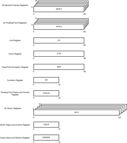
None of the PPU’s functional units can directly read from or write to main memory, so they perform their tasks by accessing data in the PPU’s user registers, shown in Figure 6.4. The GPRs and FPRs are required by the PowerPC specification, and the vector registers (VR, VSCR, VRSAVE) are needed to implement the PPU’s SIMD operations.
The functions of these registers are as follows:
General-purpose registers (GPRs)—These 64-bit registers hold data for use in fixed-point operations. In 32-bit mode, the GPRs use the low 32 bits to access memory.
Floating-point registers (FPRs)—These 64-bit registers hold values for use in floating-point operations. Double-precision and single-precision values are stored according to the IEEE-754 standard.
Link register (LR)—This 64-bit register holds the address of an upcoming branch target.
Count register (CTR)—This 64-bit register can hold either the address of an upcoming branch target or a loop counter.
Fixed-point exception register (XER)—This 64-bit register holds the carry and overflow bits resulting from fixed-point operations, and also stores the number of bytes transferred in a move-assist operation.
Condition register (CR)—This 32-bit register holds the status of arithmetic, logical, and comparison operations.
Floating-point status and control register (FPSCR)—This 32-bit register contains the status of all scalar floating-point operations.
Vector registers (VRs)—These 128-bit registers store vector data for use in vector operations.
Vector status and control register (VSCR)—This 32-bit register stores the saturation bit in the event of an overflow in a vector operation.
Vector register save and restore register (VRSAVE)—This register monitors which VRs need to be saved in the event of a context switch.
It’s important to keep in mind that these are the PPU’s user registers, also called problem-state registers. There are other registers available, such as the supervisor or privilege-state registers. They are used by the operating system to manage the Cell’s resources, and are beyond the scope of this book.
Now that you’ve seen the basic functional elements of the PPU, it’s time to see how they interact while running applications. The next section will discuss the PPU’s pipeline, or the sequence of processing stages used by the PPU to acquire and execute instructions.
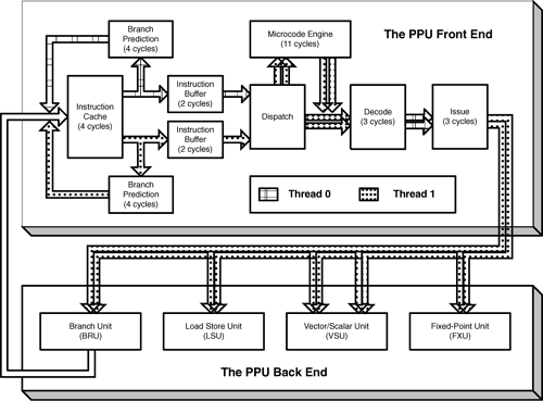
The PPU processes instructions like an assembly line: It starts with an instruction’s address and then works through a set of stages to access and execute the instruction. Like laborers on an assembly line, each processing stage performs a unique task to bring an instruction closer to completion. With each new processor cycle, the stage finishes its work and starts on a new instruction.
This assembly line is referred to as the processor’s pipeline. The PPU’s pipeline is displayed in Figure 6.5.
The pipeline is divided into two phases. The front end converts the address to an instruction and directs it to a unit that can execute it. The back end executes the instruction within one of the PPU’s four execution units: the Branch Unit (BRU), Fixed-Point Unit (FXU), Load Store Unit (LSU), or the Vector/Scalar Unit (VSU). After executing the instruction, the back end completes the operation and updates memory as needed.
Most programmers write their code in blissful ignorance of their processor’s pipeline, so why should you care about the PPU’s? I’ll tell you. Like any assembly line, the pipeline is only as efficient as the number of workers doing their jobs. If a worker has nothing to do during a cycle, that worker is wasted. In a processor pipeline, the wasted stages are called pipeline bubbles. If you know how the pipeline works, you’ll be able to prevent many of these bubbles from forming as your code executes.
To understand the PPU’s pipeline, it helps to see how instructions work their way through the processor. As an example, let’s say the Cell is running an application in 32-bit mode and its next four instructions are shown in Table 6.2.
Table 6.2. Example instructions in the PPU Pipeline
Effective Address (EA) | Command | Meaning |
|---|---|---|
0x1000 04F0 |
| Load a word from memory into Register 0. |
0x1000 04F4 |
| Compare the contents of Registers 2 and 3. |
0x1000 05F8 |
| If the compared values are equal, branch to the address given by |
0x1000 05FC |
| Load bytes of a string into consecutive registers. |
First, look at the addresses. As required by the PowerPC Specification, each instruction is 4 bytes long and word-aligned. But what exactly does 0x100004F0 refer to? Is there really a physical location in a 232 = 4GB memory space that contains the lwz opcode and its arguments? No.
The addresses in the leftmost column are effective addresses (EAs), and the Cell provides 264 or 232 of them, depending on whether it’s in 64-bit or 32-bit mode. All Cell applications access memory through effective addresses, and the EA space combines addresses for the PPE and SPE resources, but does not include memory outside the Cell.
The first instruction in the example, lwz, tells the Load Store Unit (LSU) to load a word from memory into a register. Therefore, the goal of the PPU’s front end is to find the instruction at 0x100004F0 and direct it to the LSU. Accomplishing this requires the following steps:
Before the instruction can be processed, it has to be retrieved from memory. In this example, the Instruction Unit (IU) needs to find the instruction at effective address 0x100004F0. It begins its search by looking through its L1 instruction cache (ICache). This cache can be read or written to once per cycle, and contains 32KB of memory divided into 128 sets. Each set contains two cache lines of 128 bytes each, and each set is accessed, or indexed, by the least significant bits of the instruction’s effective address.
When the right set of cache lines is found, the IU checks whether the instruction’s real address, or RA, is contained in one of its cache lines. Real addresses represent physical memory locations, and the Cell allows for 242 of them. Translating effective addresses to real addresses is usually performed by the MMU, but the IU has an array that contains recently accessed EAs and their corresponding RAs. This array is called, appropriately enough, the Instruction Effective-to-Real Address Translation array, or I-ERAT.
The IU searches the ICache and I-ERAT simultaneously, and if the real address from the I-ERAT matches the tag from one of the cache entries, a cache hit occurs. The IU finds the instruction at this address and sends it to the Instruction Buffer. If a cache hit occurs, the instruction fetch only takes four cycles.
If the cache doesn’t contain the instruction, however, fetching the instruction requires significantly more time. The IU halts while the LSU searches through memory. This search can take many cycles to perform, depending on whether the instruction is in the L2 cache, system memory, or on disk. When the LSU finds the instruction, the IU adds the new entry to the ICache and invalidates its least recently used entry.
At the same time the IU searches the I-ERAT and ICache, it also scans the Instruction Buffer for branch instructions. These come in two types: unconditional and conditional. Unconditional branches tell the IU to start processing instructions at a new address, whereas conditional branches tell the IU to go to a new address if a specific condition is reached. For example, the third command in Table 6.1, beq, is a conditional branch that means branch if equal. The second and third instructions
cmpw 2,3
beq new_address
tell the IU to compare registers 2 and 3 and, if their values are equal, continue processing the instructions stored at new_address. If the values aren’t equal, the IU should process the next command, lswi. But the IU can’t compare the registers by itself, so it makes an educated guess, and starts fetching instructions at the address it predicts will be chosen.
A wrong branch guess wastes 23 cycles. This steep penalty makes it vital to understand how branch prediction works and tailor your code accordingly. Ideally, you’ll write your code using as few branches as possible.
When the IU first encounters a conditional branch, it assumes that the instruction is part of a repetitive loop (for, while...do), and predicts the branch will go backward. This is static branch prediction. For example, a compiled for loop will usually increment a counter and branch backward until the counter reaches a specified limit. A forward branch can happen only once, so it makes sense for the IU to predict the backward branch.
When the IU determines the intended path of a branch statement, it updates its Branch History Table (BHT). Each of its 4096 entries contains a 2-bit field whose value represents the probable direction future branches will take. Then, when the IU encounters the same branch command, it accesses the BHT entry to predict the branch direction. This is dynamic branch prediction.
Once fetched, the IU stores the four instructions in one of two Instruction Buffers (IBufs), depending on which thread the instructions belong to. These IBufs function as queues, so the first instruction to enter is also the first to leave. After two stages, both IBufs release their oldest instructions to the dispatch phase.
By default, the dispatch phase alternates between threads, selecting two instructions from one thread’s IBuf and combining them into a single 8-byte field. This takes place immediately in hardware and doesn’t use up any cycles. When the cycle ends, dispatch selects two instructions from the other thread’s Instruction Buffer. After dispatch, the two selected instructions are processed in parallel unless one of them stalls the pipeline.
The dispatch phase also checks whether the instruction belongs to a specific set of microcoded instructions. If so, it enters the PPU’s microcode engine for further processing. If not, it proceeds onward for regular decoding and issue.
Microcoded instructions are more complex than regular PowerPC instructions and must be broken down into simpler instructions. The last command in Table 6.2 is lswi (load string word immediate). This instruction loads an array of 8 consecutive bytes, whose address is stored in GPR 5, into registers starting with GPR 6. This is convenient for assembly coders, who can perform multiple loads with a single instruction. But the PPU can’t process it until it’s broken down into individual load commands, and the microcode engine requires 11 stages to make this possible.
The CBE Programming Handbook puts it clearly: “Microcoded instructions should be avoided if possible.” However, these instructions are required by the PowerPC architecture, and compatibility with other 64-bit PPC systems may require them to be implemented.
After the instructions are dispatched, the IU determines which functional units should execute them. For example, the lzw command needs to be sent to the Load Store Unit (LSU), and the cmpw command needs to go to the Fixed Point Unit (FXU). This determination process is called decoding, and the pipeline requires three cycles to reduce the instruction into its opcode and arguments.
The decode phase also checks for data hazards. These take place when two instructions execute out of order, and the first instruction depends on the execution of the second. The most common is the Read-After-Write (RAW) hazard, which occurs when Instruction A tries to read a value from a register before Instruction B has a chance to update its content. Another is the Write-After-Write (WAW) hazard, which happens when two write operations are performed in the wrong order, leaving the wrong value in the register.
If no data hazard is detected, the issue stage takes three cycles to send the instructions to their appropriate execution units. If the decode stage detects a data hazard, both threads will stall as the issue phase determines the proper instruction order. Then, after reordering the instructions to remove the hazard, they will issue normally.
Each issued instruction will take one of five paths: one to the BRU, FXU, and LSU, and two to the VXU. The issue stage is capable of processing two instructions at once, and this dual-issue is an important goal, providing twice the throughput of single-issue instructions. Dual-issue is only possible when certain conditions are met, and these conditions are described shortly.
Learning about the PPU’s instruction pipeline is a lot of fun, but it’s only useful if you can optimize the operation of the pipeline in your code. In many cases, you need privileged access (beyond root) to do this, but this section covers four aspects that any user can configure: the instruction cache, branch prediction, microcoded instructions, and dual issue.
The PPU ICache is read-only and doesn’t support snooping, so there’s no way to insert new commands or directly change its contents. But you can tell the PPU to execute instructions at a new location, as long as you perform four steps:
For example, suppose you’ve created a function called routine and your application has modified the function’s instructions in main memory. You can’t immediately execute routine because the old instructions are still in the ICache. But the following commands will make sure that the new instructions are executed properly:
__icbi(&routine)  // Invalidate the cache entry containing routine
__isync()         // Wait until all previous instructions finish
routine()         // Execute the function
The __isync() intrinsic makes sure that the cache entry is invalidated before the function is executed. But because it waits for all older instructions to issue, it might require many cycles to finish.
The PowerPC instruction set contains a wide range of branch commands, and many of them provide hints that tell the IU which branch to take. But in C/C++, there are only a few ways to recommend one branch direction over another.
By default, ppu-gcc assumes that expressions inside if statements will produce a value of true. Therefore, you should position your arguments so that the first option is the most likely. Then make sure that subsequent else if statements also have the more probable option first.
Section 6.3, “PPU Instruction Processing,” described the PPU’s static and dynamic branch prediction, but you can override both with __builtin_expect(long expr, long result). The first argument is a variable or Boolean expression and the second argument is the predicted result. For example, if your code contains the statement
if (x) {...}
the compiler will predict that the value of x is nonzero. But if your code contains
if (__builtin_expect(x, 0)) {...}
the compiler will predict that x equals zero.
ppu-gcc recognizes this builtin, but you need to be certain that the expression will match the constant. The 23-cycle penalty for branch misses is so high that in most cases it’s better to allow the PPU’s branch prediction to run on its own.
It’s much easier to prevent microcoded instructions than it is to prevent branch misses. The SDK compilers provide a number of flags that either prevent these instructions or provide warnings when they are encountered. Table 6.3 lists each of them and their function.
Microcoded instructions have an advantage over regular instructions in that they take up less space in the instruction stack. However, they prevent dual-issue and the microcode engine takes 11 cycles to process them. It is recommended that you use, at least, the -mno-string and -mno-multiple flags whenever you compile code for the PPU.
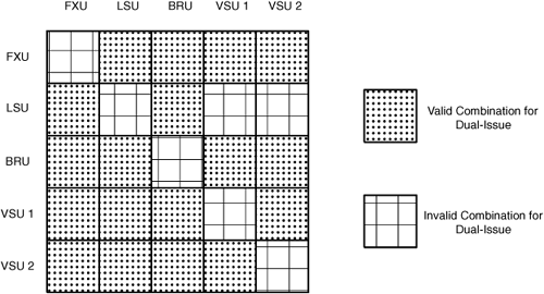
It’s difficult to control which instructions reach the issue stage together, but it’s easy to understand the requirements that must be met for dual issue to occur. The first condition is that the two issuing instructions have to be traveling to different destinations. Figure 6.6 displays the different combinations of issue routes and shows which allow dual issue and which don’t.
Note
VSU Type 2 refers to instructions that use the VSU for loading, storing, or permuting data. VSU Type 1 refers to all other instructions that use the VSU.
In addition, any of the following circumstances will prevent dual issue on the PPU:
One of the instructions is a microcoded instruction.
The Thread 0 command synchronizes communication within the Cell.
Both threads attempt to access the condition register (CR) or link register (LR).
A SIMD floating-point operation issues within two cycles of a reciprocal estimate instruction.
An instruction moves data from the floating-point status and control register (FPSCR) following a floating-point operation other than a load or store.
The topic of dual issue can be confusing, but generally speaking, as long as the two instructions don’t use the same execution unit, they can issue in parallel.
Section 6.3, “PPU Instruction Processing,” briefly described how the PPU’s two threads weave through the pipeline, but this important subject needs to be discussed in greater depth. The PPU’s threads are only semi-independent. On one hand, many of the resources that store state information, such as the general-purpose and floating-point registers, are duplicated for each thread. On the other hand, they have to share resources like the PPU’s instruction cache and execution units. Table 6.4 presents both the shared and duplicated resources within the PPU.
Table 6.4. Thread Resources—Shared and Duplicated
Shared Between Threads | Duplicated for Each Thread |
|---|---|
All caches - L1 and L2 | Instruction Buffers (IBuf) |
I-ERAT and D-ERAT arrays | Branch History Tables (BHTs) |
Microcode Engine | General-purpose registers (GPRs) |
Branch Unit (BRU) | Floating-point unit registers (FPRs) |
Fixed-Point Integer Unit (FXU) | Vector registers (VRs) |
Load Store Unit (LSU) | Condition register (CR) |
Floating-Point Unit (FPU) | Count register (CTR) |
Vector/SIMD Multimedia Extension Unit (VXU) | Link register (LR) |
Translation Lookaside Buffer (TLB) | Fixed-point exception register (XER) |
PowerPC Processor Storage Subsystem (PPSS) resources | Floating-point status and control register (FPSCR) |
Vector status and control register (VSCR) | |
Decrementer (DCR) | |
Segment Lookaside Buffer (SLB) |
The main benefit of using the PPU’s two threads is improved resource utilization. For example, if one thread needs to search through memory, the other can continue executing instructions on its own. The PPU’s dual threading doesn’t provide the same performance boost as true multicore execution, but it can provide significant benefits when used properly.
To demonstrate the benefit of dual-threaded code on the PPU, this subsection presents two methods of calculating dot products. The first example, shown in Listing 6.1, uses a single thread.
Example 6.1. Single-Threaded Dot Product: single_dot.c
#include <stdio.h>

#define N 1000

int vec1[N], vec2[N], sum;

/* Compute the dot product */
void dprod() {
   int i;
   sum = 0;
   for(i=0; i<N; i++)
      sum += vec1[i] * vec2[i];
}

int main(int argc, char **argv) {
   int i;

   /* Initialize arrays */
   for (i=0; i<N; i++) {
      vec1[i] = i;
      vec2[i] = N-i;
   }
   dprod();
   printf("Dot product = %d
", sum);
   return 0;
}
The code in Listing 6.2 uses threads to accomplish the same goal. Each of the two threads calculates half of the dot product, and the calling thread adds the results together.
Example 6.2. Dual-Threaded Dot Product: double_dot.c
#include <stdio.h>
#include <pthread.h>

#define N 1000

int vec1[N], vec2[N], sum[2];

/* Compute the odd or even dot product */
void *dprod(void *ptr) {
   int i, index = *((int*)ptr);

   sum[index] = 0;
   for(i=index; i<N; i+=2)
     sum[index] += vec1[i] * vec2[i];

   pthread_exit(NULL);
}

int main(int argc, char **argv) {
   int i;
   pthread_t threads[2];

   /* Initialize arrays */
   for (i=0; i<N; i++) {
      vec1[i] = i;
      vec2[i] = N-i;
   }

   /* Create threads to execute dot product */
   int index0 = 0;
   int index1 = 1;
   pthread_create(&threads[0], NULL, dprod, (void*)&index0);
   pthread_create(&threads[1], NULL, dprod, (void*)&index1);

   /* Wait for threads to finish */
   pthread_join(threads[0], NULL);
   pthread_join(threads[1], NULL);

   /* Add the result from each thread */
   printf("Dot product = %d
", (sum[0] + sum[1]));
   return 0;
}
When N is set to a small number, the single-threaded application runs faster. But as N increases, the performance of the dual-threaded application meets and exceeds that of the single-threaded version. The reason involves memory access: If the arrays are small, neither thread needs to search through memory, and they both constantly compete for resources. But when N is high, one thread can execute while the other waits to locate array elements.
Although useful for demonstrating dual-threaded coding, this dot-product example has little practical value. Multithreaded applications in the real world are more involved, and require more precise control than that in Listing 6.2. The intrinsic functions listed in Table 6.5 provide additional control of thread operation.
Table 6.5. PPU Intrinsic Functions for Thread Control
PPU Intrinsic Function | Function Description |
|---|---|
| Set current thread priority to High |
| Set current thread priority to Medium |
| Set current thread priority to Low |
| Delay current thread for 8 cycles at dispatch |
| Delay current thread for 10 cycles at dispatch |
| Delay current thread for 12 cycles at dispatch |
| Delay current thread for 16 cycles at dispatch |
The first three functions set a thread’s priority, which can be Low, Medium, High, or Disabled. These priorities affect the operation of the PPU’s dispatch stage; and the higher priority a thread is, the more of its instructions will be dispatched relative to a lower priority thread.
By default, all threads are set to Medium priority and dispatch operates every cycle. This also happens when both threads are set to High priority. But when both are set to Low, dispatch operates once every DISP_CNT cycles, where DISP_CNT is a bitfield in the thread switch control register (TSCR). At the time of this writing, the TSCR register has Hypervisor privilege, which means that it can’t be accessed from user-mode applications. The DISP_CNT bitfield is set to 4 by default.
If the thread priorities are High/Medium or Medium/Low, the lower-priority thread will only dispatch once in every DISP_CNT cycles. If one thread has High priority and the other has Low priority, the Low priority thread will dispatch once in every DISP_CNT cycles if the High priority thread can’t use the dispatch for itself.
The last four intrinsic functions delay the dispatch of the thread’s instructions. Whether this allows the other thread to execute depends on their relative priorities.
Now that the front end of the PPU’s pipeline has been discussed in detail, it’s time to look at the back end. This section discusses the Load Store Unit (LSU) and how it responds to memory access requests. When the LSU receives a load or store instruction, it searches through the L1 data cache first. If it doesn’t find what it’s looking for, it sends a request to the L2 cache. If it’s not there either, the MMU translates the effective address to a real address so that the LSU can search through main memory.
The LSU is particularly important to understand because it contains the PPU’s data cache. A number of useful intrinsics allow you to add and remove cache entries, and the more you take advantage of them, the more efficiently your code will execute. These intrinsics can also affect the operation of the PPU’s L2 cache.
The first instruction in Table 6.2 is lwz, which loads a word from memory into a register and clears the register’s high bits if needed. When the LSU receives this instruction from the IU, it accesses its L1 DCache and its Data Effective-to-Real Address Translation (D-ERAT) array. These resources function similarly to the ICache and I-ERAT described in Section 6.3, “PPU Instruction Processing.” That is, the D-ERAT translates the EAs of recently accessed data to their RAs, and the DCache returns the data at the RA.
Like the ICache, the DCache size is 32KB and stores data in 128-byte cache lines. But one important difference is that whereas the ICache is read-only, you can update and modify the DCache in code. Table 6.6 lists the intrinsics that make this possible.
Table 6.6. PPU Intrinsic Functions for Updating the DCache
PPU Intrinsic Function | Full Name | Function Description |
|---|---|---|
| Data Cache Block Touch | Tells cache that the entry containing |
| Data Cache Block Touch For Store | Tells cache that the entry containing |
| Data Cache Block Store | Writes the memory location containing |
| Data Cache Block Flush | Removes the cache entry containing |
| Data Cache Block Set to Zero | Sets the cache block containing |
| Sync | Ensures all previous instructions are completed before continuing |
| Light-Weight Sync | Ensures that all LS instructions are completed before continuing |
| Enforce In-Order Execution of I/O | Ensures that writes to memory are completed before further writes |
The two block touch intrinsics, __dcbt() and __dcbtst(), load a new cache line into DCache if the data is already present in the L2 cache and no access faults occur. The only difference between the two instructions is seen when the data isn’t in the L2 cache. In this case, __dcbt() updates the L2 cache but not the DCache, and __dcbtst() updates both the L2 cache and the DCache.
__dcbst() and __dcbf() both write a block of cached data to main memory. The difference is that __dcbf() invalidates the cache entry and __dcbst() leaves the entry valid. In many cases, the IU completes these commands before main memory is actually updated, so it’s important to follow them with functions like __sync() to ensure that they are performed properly.
The last three intrinsics in Table 6.6 constrain the PPU to execute memory access operations in a specific order. __eieio() is the least constraining, and requires that all memory writes before the command be accomplished before further writes are started. __lwsync() tells the PPU to complete all previous reads and writes before continuing to following instructions. __sync() is similar to __lwsync(), but forces all previous instructions to complete before continuing. __sync() is the most constraining of the context-synchronizing instructions, and therefore requires the most number of cycles to complete.
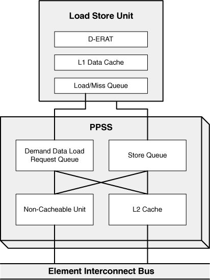
If the LSU can’t find data in the DCache, it sends a request to its Load-Miss Queue (LMQ). This queue holds eight requests for the L2 cache, and sends them to the PowerPC Processor Storage Subsystem (PPSS). Figure 6.7 shows the PPSS resources used in data retrieval, particularly the connections between the LSU, PPSS, and Element Interconnect Bus (EIB).
Within the PPSS, the Demand Data Load Request Queue (DLQ) receives the data requests from the LMQ. If the memory location is marked as Caching-Inhibited, the DLQ passes the request to the Noncacheable Unit (NCU). If the memory location is cacheable, it passes the request to the L2 cache.
This cache stores 512KB of instructions and data. Like the ICache and DCache, these lines each store 128 bytes, and the cache can be read or written to only once per cycle. However, the lines are organized in sets of 8, and the L2 cache only uses real addressing for its index and tag memory. This is because the LSU already has the RA of the memory location it is trying to access.
The L2 cache is write-back. That is, when the LSU makes a write request to an already-cached location, it updates the cache’s data but not main memory. The cache updates main memory only when the updated cache entry is removed from the cache. By postponing communication with main memory until it’s necessary, this keeps memory traffic to a minimum.
If you’re building an operating system or hypervisor for the PPU, you can configure the cache to be direct mapped or change the cache management algorithm. But if you’re running applications in user mode—even as root—the only tools you have to update the cache are the instrinsics presented in Table 6.6.
When the ERATs fail to translate effective addresses to real addresses, the MMU takes on the task of address translation. This unit organizes the PPU’s virtual memory into segments and pages, and uses a Translation Lookaside Buffer (TLB) to keep track of recently accessed page table entries.
This section explains how effective addresses (EAs) are converted into virtual addresses (VAs), and from there into real addresses (RAs). PPU memory management becomes very important when your application requires large chunks of memory, for performance will degrade dramatically if the page sizes are too small.
When multiple applications are open at the same time, the operating system may need to supply more memory than is available in RAM. To make this possible, the OS expands its address space and provides a means of transferring additional memory to and from disk storage. This expanded address space is called virtual memory, and the MMU supplies 265 virtual addresses, orVAs. The memory transfer between RAM and disk is performed using blocks of data called pages.
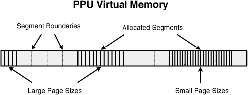
The operating system provides virtual memory to a process by allocating one or more 256MB blocks called segments. These segments may not overlap, and as shown in Figure 6.8, each is composed of multiple pages. Each page can be 4KB or two sizes selectable from 64KB, 1MB, or 16MB. Pages in a segment must have the same size, but pages in different segments may have different sizes.
Note
The Linux operating system does not support 16MB pages, called hugepages, by default. The kernel must be recompiled and reloaded to enable this capability. This recompilation process is discussed in Appendix B, “Updating the PS3 Add-On Packages and Installing a New Linux Kernel.”
Processes receive sections of virtual memory from the OS, but they use effective addresses in their programs. Therefore, the MMU must translate between EAs (64-bit addresses) and VAs (65-bit addresses). Segments play a crucial role in this translation, and the first step taken by the MMU is to find out which segment contains the translated EA.
The virtual memory space contains a maximum of 237 segments, and each segment is identified by a 37-bit address called its virtual segment ID, or VSID. Similarly, the 36 MSBs of an effective address are called the address’s effective segment ID, or ESID. To determine which segment an EA belongs to, the MMU accesses specific sections of memory that match VSIDs to ESIDs. These sections of memory are called Segment Lookaside Buffer Entries, or SLBEs. Figure 6.9 shows how SLBEs provide this effective-to-virtual address matching.
There can only be one SLBE per segment. In addition to the ESID and VSID, each entry stores auxiliary data about the segment. This includes whether the segment is valid, whether it is executable, and the size of the pages in the segment.
These entries are stored in one of two Segment Lookaside Buffers (SLBs), both located inside the MMU. There is one SLB for each processing thread, and each SLB can store up to 64 SLBEs. If the SLB fails to match an ESID to a VSID, an error occurs: An Instruction Segment exception is thrown if the search was for an instruction; a Data Segment exception is thrown if the search was for data.
In addition to the VSID, each virtual address also contains 28 bits that precisely locate each byte in the segment. One set of these bits identifies the virtual page, and the size of the set depends on the page size. The combination of theVSID and these page bits is called a page’s virtual page number, orVPN. EachVPN locates a virtual page in virtual memory.
The real address space (242 addresses) is also divided into pages that are identified by real page numbers (RPNs). These pages are represented by entries in the MMU’s page table, and each page table entry (PTE) matches a page’s RPN to a VPN. The final step in the MMU’s translation is to find the PTE corresponding to the VA and use the VPN to determine the RA.
Searching through the page table takes a great deal of time. To reduce the time needed to match VPNs to RPNs, the Translation Lookaside Buffer (TLB) stores recently accessed PTEs in the same way that a cache stores recently accessed data. If the LSU searches for data in a page whose PTE is stored in the TLB, a TLB hit occurs. If the TLB doesn’t contain an entry for the page being accessed, however, the result is a TLB miss.
When the TLB can’t match a virtual page to a real page, the MMU must search through the page table for the right PTE and update the TLB. This takes many, many cycles to perform and must be avoided at all costs. There’s no way to modify the TLB directly in a user-mode application, but you can prevent TLB misses by using large pages. This reduces the number of PTEs in the page table and reduces the number of pages your application will need.
The largest possible page size is 16MB, but this isn’t enabled by default. Appendix B discusses the process of configuring hugepages in the Linux kernel. Chapter 16, “Vectors and Matrices,” explains how hugepages are used to compute the product of two very large matrices.
When it comes to the Cell’s processing resources, SPUs get most of the attention. But whereas SPUs are limited in the tasks they can execute efficiently, the PPU can perform a wide range of operations. The goal of this chapter has been to introduce the PPU’s operation and structure, and show how it processes instructions and accesses memory.
IBM designed the PPU to provide a maximum of capability while requiring a minimum of power and chip space. It contains the same functional units as the PowerPC 970, but removes unit redundancy and out-of-order execution. The burden of ordering code is placed on the compiler and the programmer, which makes it important to understand how the PPU’s pipeline works and how to remove bubbles.
This chapter concludes with an in-depth discussion of memory access using the Load Store Unit (LSU) and the Memory Management Unit (MMU). The LSU searches through the L1 and L2 caches for data, and turns to the MMU when it can’t find what it’s looking for. The MMU goes through a complex process of translating effective addresses to virtual addresses and finally to real addresses. This process may not seem exciting to general software developers, but it’s important to understand how to update the data cache and use the large page sizes for process data.
