
17
Internal Structure of FreeRTOS
CONTENTS
17.1 Task Scheduler/Context Switch
17.2 Synchronization Primitives
This chapter presents the internal structure of FreeRTOS [13]. It is hence related to Chapter 8, which describes the features and the applications programming interface of the same real-time operating system. It is also useful to read it together with Chapter 18, which discusses the internal structure of a couple of Linux real-time extensions.
The comparison shows how the target hardware architecture, design principle, backward compatibility, standard conformance, as well as the number and degree of sophistication of the features to be provided are all aspects that have significant effects on the internal structure of an operating system, leading to very different solutions to the same problems.
17.1 Task Scheduler/Context Switch
The FreeRTOS scheduler is extremely simple but also very effective from a real-time execution standpoint. It is a fixed-priority scheduler, and hence, it can directly support both the Rate Monotonic (RM) and Deadline Monotonic (DM) scheduling algorithms discussed in the previous chapters.
Figure 17.1 depicts the main data structures handled by the FreeRTOS scheduler. Most of them are built upon a simpler data structure called xList, a doubly linked list that implements an ordered queue. Individual xList items hold a pointer to another data structure that represents the information associated with the item.
Even if, in principle, the data structure linked to an xList item can be chosen at will, in most cases it is a Task Control Block (TCB). This is the main data structure used by the operating system to represent a task and to store any information associated with it. The list header also contains a count of how many elements currently are in the list, to speed up common operations like checking whether a list is empty or not.
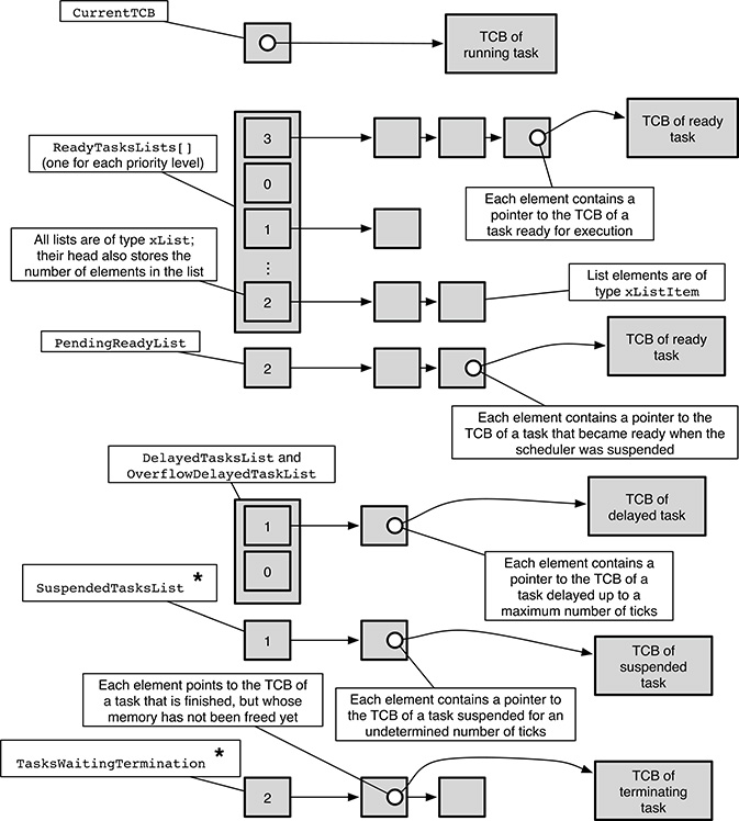
FIGURE 17.1
Simplified view of the data structures used by the FreeRTOS scheduler. The elements marked with * are optional; they may or may not be present, depending on the FreeRTOS configuration.
In Figure 17.1, an xList is represented by a sequence of ordered grey boxes connected by arrows. The leftmost box is the list header, and the number within it indicates how many elements currently belong to the list. The next boxes represent list elements; each of them points to a TCB, although, for clarity, not all of them are shown in the figure.
It should also be noted that the actual implementation of an xList is slightly more complicated than what has been described so far. That is, it actually is a circular list and incorporates a guard element to delimit its end. However, those additional details are mainly related to compactness and efficiency, and do not significantly change the underlying idea.
The main components of the scheduler data structures are
The
CurrentTCBpointer designates the TCB of the running task. There is only one instance of this pointer, because FreeRTOS only supports single-processor systems, where at the most, one process can be running at a time.ReadyTaskLists[]is an array ofxListdata structures, one for each priority level configured in the system. ThexListcorresponding to a certain priority links together all tasks that have that priority and are ready for execution. This is the main data structure consulted by the scheduler when it is about to run a task. It should be noted that, for convenience, the running task is linked to the ready list corresponding to its priority, too.A task may become ready for execution while the scheduler is suspended and the
ReadyTaskLists[]cannot be manipulated directly. In this case, the task is temporarily “parked,” by linking its TCB to thePendingReadyListlist. The elements of this list are moved into the proper position ofReadyTaskLists[], depending on their priority, as soon as the scheduler becomes operational again and before any scheduling decision is taken.Both the
DelayedTaskListand theOverflowDelayedTaskListcontain tasks that are delayed, that is, they are waiting until some instant in the future, expressed in ticks. Both are ordered by increasing time so that the tasks nearer to the front of the lists have their timeouts expiring first. The need for two lists stems from the fact that the operating system tick counter is an unsigned integer with a limited number of bits and will necessarily overflow with time.Therefore,
DelayedTaskListcontains the tasks with a timeout within the current tick counter span before the next overflow, whereasOverflowDelayedTaskListholds the tasks with a timeout beyond the next tick counter overflow. Those timeouts belong to the future even if their numeric value is lower than the current value of the tick counter, so putting them in the same list as the others would lead to confusion.The
SuspendedTaskListholds the TCBs of all tasks that are currently suspended, that is, those that are waiting for an undetermined number of clock ticks. This list is needed only if FreeRTOS has been configured to support task suspension. Such a configuration is needed to support infinite timeouts in interprocess communication as well as explicit task suspension.Last, the
TasksWaitingTerminationlist collects all tasks that are finished but that have not yet been removed from the system because the memory associated with them has not yet been freed. For a variety of reasons, this last operation in the lifetime of a task is accomplished by the idle task, running at the minimum priority in the system. Hence, finished tasks may spend a nonnegligible amount of time in this list if the system is busy.
TABLE 17.1
Contents of a FreeRTOS Task Control Block (TCB)
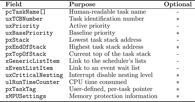
As said before, in FreeRTOS each task is represented by a data structure called TCB, containing a number of fields. Some of them are always present; others are optional, in order to save space, because they are needed only for certain operating system configurations. As shown in Table 17.1, the TCB contains many of the elements that were discussed in the previous chapters, namely,
pcTaskNameholds the human-readable task name as a character string. This information is not directly used in any way by the scheduler but may be useful to identify the task for debugging purposes.Its machine-readable counterpart is the
uxTCBNumber. This field is present only if the FreeRTOS runtime trace facility has been configured, and is a unique number that represents the task.uxPriorityrepresents the current, or active, priority of the task used by the scheduling algorithm.When the system has been configured to support mutual exclusion semaphores with priority inheritance, the previous field is complemented by
uxBasePriority, which represents the baseline priority of the task.pxStackpoints to the area of memory used to store the task stack. Regardless of the direction in which the stack grows on a certain architecture (toward higher or lower addresses), this field always points to the base of the area, that is, its lowest address.For architectures in which task stacks grow upward, that is, toward higher addresses,
pxEndOfStackpoints to the highest, legal stack address. This information is required to perform stack occupancy checks.pxTopOfStackpoints to the top of the task stack. This information is used for two distinct, but related, purposes:When the task context is saved, most of the task state information is pushed onto its stack; the pointer is used to later retrieve this information.
The value of the stack pointer itself is part of the task state, and hence, the pointer is also used to restore the task stack pointer to the right value during context restoration.
The
xGenericListItemfield is used to link the task control block to one of the lists managed by the scheduler, depending on the task state. In particular,it links the task to one of the
ReadyTaskLists[]when the task is ready or running;it links the task to the
TasksWaitingTerminationlist when the task is finished but its memory has not been freed yet;it links the task to either the
DelayedTaskListor theOverflowDelayedTaskListwhen the task is being delayed for a certain number of ticks;it links the task to the
SuspendedTaskListwhen the task is suspended for an undetermined number of ticks.
The
xEventListItemfield is used in a similar way when a task is waiting for an event to occur on an intertask synchronization/communication object and must hence be linked to two distinct lists at the same time. For example, when a task waits to receive a message from an empty message queue, itsxEventListItemfield links it to one of the waiting lists associated to the message queue, the one that groups all tasks that are waiting for a message to arrive.At the same time, its
xGenericListItemfield links it to either one of the delayed task lists (if the task specified a finite timeout for the receive operation) or to the suspended task list (if no timeout was specified).In addition, the
xEventListItemfield is also used to temporarily link the task to thePendingReadyList. This is done when a task becomes ready while the scheduler is suspended and is hence impossible to put it back into one of theReadyTaskLists[]directly.The interrupt disable nesting level indicates how many nested critical regions protected by disabling interrupts are currently in effect for a given task. It is used to properly reenable interrupts when the outermost critical region concludes, that is, when the nesting level goes back to zero. In some architectures, this datum is held within the TCB in the
uxCriticalNestingfield.The
ulRunTimeCounteris present in the TCB only when FreeRTOS has been configured to collect runtime statistics. It represents how much time has been spent running the task from its creation. It should be noted that its value is not derived from the operating system tick but from a separate, architecture-dependent timer. Hence, its resolution and unit of measurement may not be the same.pxTaskTagholds a pointer that can be uniquely associated with the task by the user. It is useful, for example, to store a pointer to a data structure holding additional user-defined, per-task information besides what is held in the TCB itself.If the architecture supports memory protection among tasks, the
xMPUSettingspoints to an architecture-dependent data structure. Its contents are used during context switch to reprogram the Memory Protection Unit (MPU) according to the requirements of the task to be executed next.
An interesting omission in the FreeRTOS TCB is the task state, that is, its location in the process state diagram. However, this information can easily be inferred, by looking at which lists the TCB is currently linked to, through xGenericListItem and xEventListItem. The TCB of the running task can be reached directly through the CurrentTCB pointer.
Another thing that is seemingly missing is the processor state information pertaining to the task, that is, the value of the program counter, general registers, and so on. In FreeRTOS, this information is pushed onto the task stack when its context is saved. Therefore, even if it is not stored in the TCB directly, it can still be retrieved indirectly because the TCB does contain a pointer to the top of the stack, pxTopOfStack. This is the situation shown for task B in Figure 17.2.
We can now start discussing how FreeRTOS implements a context switch in practice. In particular, let us assume that task A is currently running and the operating system is about to switch to task B, which is ready for execution.
The status of the main data structures involved in this context switch before it begins is shown in Figure 17.2. Since task A is being executed, its processor state (depicted as a dark grey block in the figure) is actually within the CPU itself. The CPU stack pointer points somewhere within task A’s stack and delimits the portion of stack currently in use by the task (the light grey zone) from the free stack space (the white zone). For the sake of the example, stacks are assumed to grow downward in the figure.
While task A is running, the stack pointer value evolves according to what the task itself is executing. On most architectures, if task A performs a function call, the function arguments and program counter are pushed onto the stack, and the stack pointer is moved down. When the function returns to the caller, this information is popped from the stack and the stack pointer goes up to its original place.
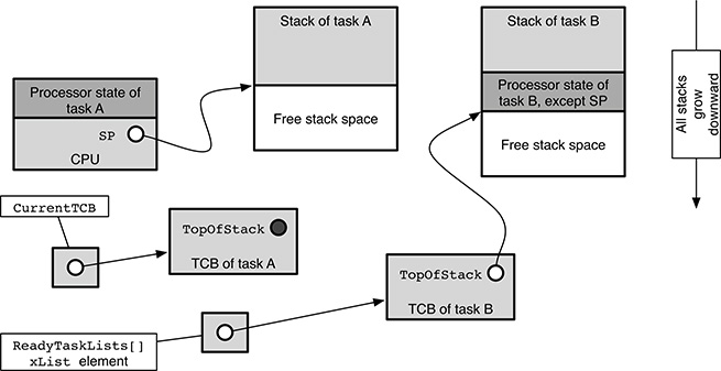
FIGURE 17.2
State of the main FreeRTOS data structures involved in a context switch when it is executing task A and is about to switch to task B.
The TCB of the running task, A in this case, can be reached from the CurrentTCB pointer. Since the TCB does not hold a valid stack state at this moment, its pxTopOfStack field has no particular meaning and is shown as a black dot.
The situation is different for what concerns task B because it is indeed ready for execution but not running. First of all, its TCB is linked to one of the ReadyTaskLists[], the one pertaining to its priority, by means of an xList element. Since B is not being executed at the moment, its processor state does not reside in the CPU, as it was for task A. Instead, most of it has been pushed onto its own stack when its context was last saved. The only exception is the stack pointer, which is stored in B’s TCB instead, namely, in the pxTopOfStack field.
Let us now assume that the operating system is about to reevaluate the scheduling algorithm. This happens for a variety of reasons already discussed in Chapter 12. For example, a task with a priority higher than the running task may become ready for execution.
This event must not disrupt the execution of the running task, A. Therefore, as shown in Figure 17.3, the operating system must first of all save the context of task A onto its own stack and then update its TCB so that the pxTopOfStack field points to the information just saved. In this way, the saved task context is made accessible from the TCB itself.
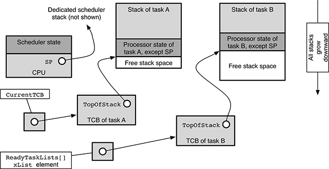
FIGURE 17.3
State of the main FreeRTOS data structures involved in a context switch when the context of task A has been saved and the scheduler is about to run.
At this point, the processor stack pointer is also switched to a dedicated kernel stack, and hence, the processor can safely be used to execute the scheduling algorithm without fear of damaging the context of any task in the system. The final result of the scheduling algorithm is an update of the scheduler data structures, namely, to the CurrentTCB pointer.
In particular, as shown in Figure 17.4, if we suppose that the scheduling algorithm chooses B as the next task to be executed, it updates the CurrentTCB pointer so that it refers to the TCB of task B.
It should also be noted that immediately before the context switch takes place, further updates to the data structures may be necessary, depending on the reason of the context switch itself. The figure refers to the simplest case, in which a context switch is needed due to the readiness of a higher-priority task (B) and the currently executing task (A) is still ready for execution.
In this case, the TCB of A should, in principle, be linked back to one of the ReadyTaskLists[] according to its priority. Actually, as an optimization, FreeRTOS never removes a task from its ready list when it becomes running, so this operation is unnecessary. More complex scenarios involve intertask synchronization or communication and will be discussed in Section 17.2.
The last step of the context switch is to restore the context of task B to resume its execution. The final state of the system is depicted in Figure 17.5. After context restoration, the processor state of task B has been loaded into the processor, and the processor stack pointer has been brought back exactly where it was when the context of B was saved. Indeed, by comparing Figures 17.2 and 17.5, it can be seen that they are exactly equivalent, with the roles of tasks A and B interchanged.
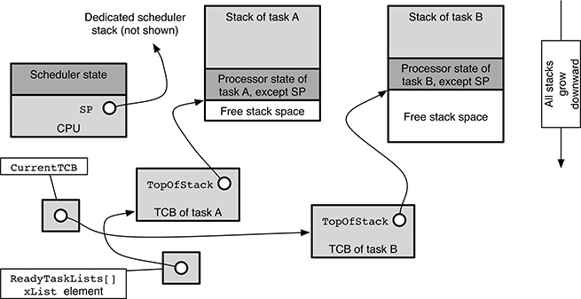
FIGURE 17.4
State of the main FreeRTOS data structures involved in a context switch when the scheduling algorithm has chosen B as the next task to be executed.
17.2 Synchronization Primitives
The most basic intertask communication and synchronization object provided by FreeRTOS is the message queue. All other objects, for instance semaphores, are built upon it. A message queue is represented by the xQUEUE data type, linked to a separate message storage zone. Table 17.2 gives a detailed list of the data structure contents, while Figure 17.6 shows a simplified summary of the state of a message queue in two distinct scenarios:
when it contains 3 messages out of a maximum capacity of 6, and there are no tasks waiting to send or receive messages;
when it is completely empty and there are two tasks waiting to receive a message from it.
All xQUEUE fields are always present regardless of the FreeRTOS configuration. Their purpose is
Fields
uxLengthanduxItemSizeindicate the “geometry” of the message queue, that is, what is the maximum number of messages that it can hold, and the size of each message in bytes, respectively.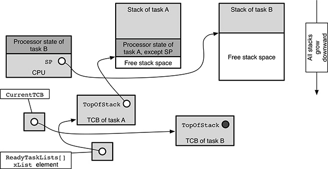
FIGURE 17.5
State of the main FreeRTOS data structures involved in a context switch after the context of task B has been restored.pcHeadandpcTaildelimit the message storage zone associated with the queue. In particular,pcHeadpoints to the base, that is, the lowest address of the memory area, andpcTailpoints to one byte more than the highest address of the area.A separate message storage zone is used, instead of embedding it into the
xQUEUE, so that the mainxQUEUEdata structure always has the same length and layout regardless of how many messages can be stored into it, and their size.pcReadFromandpcWriteTodelineate the full portion of the message storage zone, which currently contains messages, and separate it from the free message storage space. It should be remarked that the meaning of thepcReadFromdiffers from the meaning ofpcWriteToin a slightly counterintuitive way: whilepcWriteTopoints to the first free slot in the message storage zone,pcReadFrompoints to the element that was last read from the queue. As a consequence, the oldest message in the queue is not pointed directly bypcReadFrombut resides one element beyond that.These pointers are used by tasks to know where the oldest message currently stored in the queue starts (at the location pointed by
pcReadFromplus the item size) and where the next message must be written (at the location pointed bypcWriteTo).Overall, the message storage zone is managed as a circular buffer to avoid moving messages from one location to another within the storage area when performing a send or receive operation. Hence, both pointers wrap back to
pcHeadwhenever they reachpcTail.TABLE 17.2
Contents of a FreeRTOS message queue data structure (xQUEUE)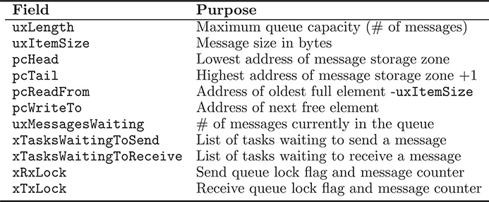
uxMessagesWaitingcounts how many messages are currently stored in the queue.The
xTasksWaitingToSendfield is anxListthat links together all the tasks waiting to send a message into the queue when that operation cannot be performed immediately because the queue is completely full. The tasks are arranged in priority order so that the highest-priority task is awakened first when a free message slot becomes available.The
xTasksWaitingToReceivefield is anxListthat has the same purpose asxTasksWaitingToSendbut for tasks waiting to receive a message from an empty queue.In FreeRTOS, Interrupt Service Routines (ISRs) can use message queues to send messages to regular tasks, and receive messages from them, by means of special, nonblocking functions. In some cases—namely, if the ISR is executed while a task is working on the
xQUEUE—these functions are still allowed to send and receive messages, but must not update the waiting task lists associated to the queue,xTasksWaitingToSendandxTasksWaitingToReceive. This is necessary to ensure that the data structures just mentioned remain consistent.When this is the case, the fields
xRxLock(for the receive part) andxTxLock(for the send part) are set to a special value to indicate that the queue is “locked.” When the queue is locked, the same fields are also used to count how many messages have been received from, and sent to, the queue by an ISR without updating the waiting task lists. The value is used, as soon as the queue is unlocked, to bring the queue data structure back to consistency.
As an example, let us see what happens when the running task invokes a receive operation on an empty message queue. The following sequence of events takes place:
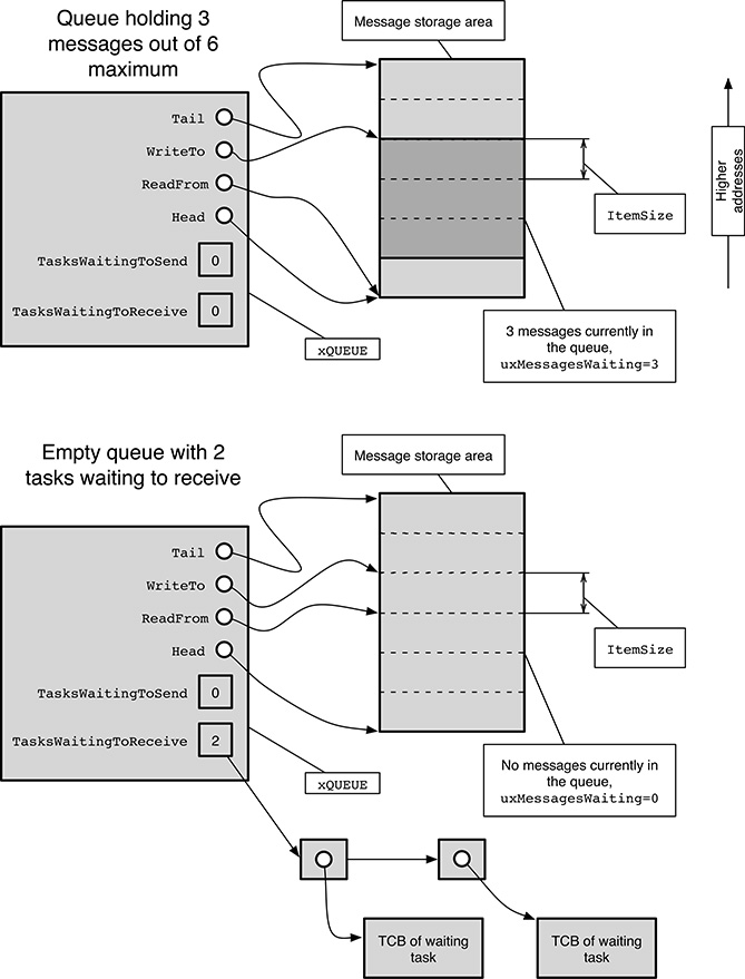
FIGURE 17.6
Simplified depiction of a FreeRTOS message queue.
Within a critical section, protected by disabling interrupts, the task checks if the value of the
uxMessagesWaitingfield is greater than zero. If this is the case, at least one message is already stored in the queue, and the task can retrieve it immediately without blocking. During the check, neither other tasks nor ISRs are allowed to operate on the queue because interrupts are disabled in order to guarantee its consistency.If the queue is empty, the task exits from the “strong” critical section just discussed and enters a “weaker” critical section, protected by disabling the operating system scheduler. Within this critical section, the running task cannot be preempted but interrupts are enabled again, and hence, the task locks the queue against further updates from ISRs by means of the fields
xRxLockandxTxLock.At first sight, having two distinct critical sections arranged in this way may look like a useless complication. However, as it will become clearer from the following description, the operations contained in the weaker critical section require a relatively long execution time. Hence, especially in a real-time system, it is important to keep interrupts enabled while they are carried out, even at the expense of making the code more involved.
If the timeout of the receive operation has already expired at this point, the queue is unlocked and the operation is concluded with an error indication.
If the timeout of the receive operation is not yet expired (or no timeout was specified) and the queue is still empty—some messages could have been sent to the queue between the two critical sections—the task is blocked by removing it from the element of
ReadyTaskLists[]it belongs to and then linked to either one of the delayed task lists (if the task specified a finite timeout for the receive operation) or to the suspended task list (if no timeout was specified). In addition, the task is also linked to thexTasksWaitingToReceivelist associated to the queue.At this point, the queue is unlocked and the scheduler is reenabled. If the current task was blocked in the previous step, this also forces a context switch to occur.
Moreover, unlocking the queue may also wake up some tasks blocked on either
xTasksWaitingToReceiveorxTasksWaitingToSend. This is necessary because ISRs are allowed to send and receive messages from the queue while it is locked, but they are not allowed to update the waiting task lists. This update is therefore delayed and performed as soon as the queue is unlocked.
The whole sequence outlined above is repeated to retry the receive operation whenever the task is awakened. This may happen either because the receive timeout expired or more messages were sent to the queue. In the first case, the next receive attempt will necessarily fail because the timeout expiration will definitely be detected.
However, in the second case, the receive operation is not necessarily bound to succeed on the next attempt because other, higher-priority tasks may “steal” all the messages sent to the queue before the current task had a chance of running. In this case, the task will find that the queue is empty and block again.
TABLE 17.3xQUEUE fields that have a different meaning when the message queue supports a mutual exclusion semaphore with priority inheritance
| Original name | New name | Purpose |
pcHead |
uxQueueType |
Queue type |
pcTail |
pxMutexHolder |
Task owning the mutex |
pcReadFrom |
uxRecursiveCallCount |
Critical region nesting counter |
All other communication and synchronization objects provided by FreeR-TOS are directly layered on message queues. For example, a counting semaphore with an initial value of x and a maximum value of y is implemented as a message queue that can hold at most y zero-byte messages, with x dummy messages stored into the queue during initialization. Binary semaphores are handled as a special case of counting semaphores, with y = 1 and either x = 0 or x = 1.
Mutual exclusion semaphores are an important exception because FreeR-TOS implements the priority inheritance algorithm for them and supports the recursive lock and unlock feature for them. As a consequence, the message queue mechanism just described cannot be applied as it is. Just to make an example, task priorities are obeyed but never modified by the message queue operations discussed so far.
On the one hand, to implement the priority inheritance algorithm, more information is needed than it is provided by the xQUEUE data structure discussed so far. On the other hand, several fields in the same data structure are unneeded when it is used to support a mutual exclusion semaphore rather than a true message queue.
Hence, as shown in Table 17.3, several xQUEUE fields get a different name and meaning in this case, such as:
As seen in Table 17.2, for regular message queues, the
pcHeadfield holds the lowest address of the message storage zone associated with the queue. However, as discussed before, message queues used to build semaphores hold zero-size messages, and thus, no memory at all is actually needed to store them; only their count is important.For this reason, the
pcHeadfield—now renameduxQueueType—is initialized to aNULLpointer to indicate that the message queue is indeed a mutual exclusion semaphore.Likely, the
pcTailfield—now calledpxMutexHolder—is used to store a TCB pointer. The pointer may be eitherNULL, to signify that the mutual exclusion semaphore is currently free, or refer to the TCB of the task that currently owns the mutex. In this context, owning the mutex means that the task is currently within a critical region controlled by that semaphore.Moreover, for a recursive mutual exclusion semaphore, it is necessary to hold a count of how many nested critical regions, controlled by a certain semaphore, have been entered by the task owning that semaphore but have not been exited yet. This count is stored in the
uxRecursiveCallCountfield, which now takes the place of thepcReadFrompointer.
17.3 Porting FreeRTOS to a New Architecture
To enhance their portability to different processor architectures, software development systems (also known as toolchains), and hardware platforms, most modern operating systems, including FreeRTOS, specify a well-defined interface between the operating system modules that do not depend on the architecture, and the architecture-dependent modules, often called Hardware Abstraction Layer (HAL).
As their name suggests, those modules must be rewritten when the operating system is ported to a new architecture, and must take care of all its peculiarities. Moreover, they often include driver support for a limited set of devices needed by the operating system itself and the language support library. For instance, FreeRTOS needs a periodic timer interrupt to work properly; moreover, an Input/Output console can be very useful when applications are tested and debugged.
We will now discuss the main contents of the FreeRTOS architecture-dependent modules, referring to the ARM Cortex-M3 port of FreeRTOS when concrete examples and code excerpts are needed. More information about the architecture can be found in References [6, 7]. This family of microcontrollers has been chosen because it is a typical representative of contemporary, low-cost components for embedded applications and, at the same time, it is simple enough so that the reader can gain a general understanding of architecture-dependent modules without studying the architecture in detail beforehand.
In most cases, the bulk of the port to a new architecture is done by defining a set of C preprocessor macros in the architecture-dependent file portmacro.h. During the build, the contents of this file are incorporated by means of a conditional #include directive contained in the FreeRTOS header file portable.h.
In turn, the conditional inclusion is controlled by an architecture and toolchain-dependent preprocessor symbol, GCC_ARMCM3, for the Cortex-M3 and the GNU toolchain. The final result is that that the correct header for the architecture being targeted by the build and the toolchain being used is included.
The first thing to be found in portmacro.h is a mapping of some abstract data types required by FreeRTOS into the corresponding data types supported by the compiler:
1 # define portCHAR        char
2 # define portFLOAT       float
3 # define portDOUBLE      double
4 # define portLONG        long
5 # define portSHORT       short
6 # define portSTACK_TYPE  unsigned portLONG
7 # define portBASE_TYPE   long
For example, the code excerpt shown above states that, for the Cortex-M3, the FreeRTOS data type portCHAR (an 8-bit character) corresponds to the C language data type char. Even more importantly, it also states that portBASE_TYPE, the most “natural” integer data type of the architecture, which usually corresponds to a machine word, is a long integer. Similarly, the portSTACK_TYPE is used as the base type for the task stacks, and its correct definition is crucial for correct stack alignment.
Then, the data type used by FreeRTOS to represent time, expressed in ticks, must be defined. This data type is called portTickType and it is defined as follows:
1 #if( configUSE_16_BIT_TICKS == 1 )
2         typedef unsigned portSHORT portTickType;
3 #       define portMAX_DELAY ( portTickType ) 0 xffff
4 # else
5         typedef unsigned portLONG portTickType;
6 #       define portMAX_DELAY ( portTickType ) 0 xffffffff
7 # endif
As can be seen, the definition is both architecture dependent (through the macros portSHORT and portLONG) and configuration dependent (through the configuration option configUSE_16_BIT_TICKS). Since the definition of portTickType affects the maximum relative delay in ticks that can be represented by the operating system and used by applications, the fragment of code also defines the portMAX_DELAY macro accordingly.
More architecture-dependent information is conveyed by means of the following, additional definitions:
1 # define portSTACK_GROWTH ( -1 )
2 # define portTICK_RATE_MS ( ( portTickType ) 1000 / configTICK_RATE_HZ )
3 # define portBYTE_ALIGNMENT 8
The first definition states that, on this architecture, stacks grow downward. The macro can also be defined as ( +1 ) to denote that they grow upward instead. The second definition determines the length of a tick in milliseconds, starting from the configuration option configTICK_RATE_HZ. The last one expresses the strongest memory alignment constraint of the architecture for any kind of object in bytes. In this case, the value 8 means that a memory address that is a multiple of 8 bytes is good for storing any kind of object.
The next definition concerns portYIELD, the function or macro invoked by FreeRTOS to perform a context switch from the current task to a new one chosen by the scheduling algorithm. In this case, this activity is delegated to the architecture-dependent function vPortYieldFromISR:
1 extern void vPortYieldFromISR( void );
2 # define portYIELD()      vPortYieldFromISR()
For some architectures, the code to be executed for a context switch is not always the same, as in this case, but depends on the execution context it is invoked from. In this case, the additional macros portYIELD_FROM_ISR and portYIELD_WITHIN_API must be defined. They are used to ask for a context switch from an ISR or the FreeRTOS applications programming interface (API) functions, respectively.
The last set of architecture-dependent definitions found in portmacro.h are a bit more involved because they are concerned with interrupt handling:
 1   # define   portSET_INTERRUPT_MASK()
 2             __asm    volatile
 3             (
 4                "      mov r0 ,  %0
"
 5                "      msr basepri , r0
"
 6                ::"i"( configMAX_SYSCALL_INTERRUPT_PRIORITY):"r0"
 7             )
 8
 9   # define   portCLEAR_INTERRUPT_MASK()
10             __asm    volatile
11             (
12                "      mov r0 ,  #0
"
13                "      msr basepri , r0
"
14                :::"r0"
15             )
16
17   # define   portSET_INTERRUPT_MASK_FROM_ISR()
18             0; portSET_INTERRUPT_MASK()
19
20   # define   portCLEAR_INTERRUPT_MASK_FROM_ISR(x)
21             portCLEAR_INTERRUPT_MASK();( void)x
22
23   extern    void vPortEnterCritical(   void );
24   extern    void vPortExitCritical(   void );
25
26   # define   portDISABLE_INTERRUPTS()    portSET_INTERRUPT_MASK()
27   # define   portENABLE_INTERRUPTS()       portCLEAR_INTERRUPT_MASK()
28   # define   portENTER_CRITICAL()           vPortEnterCritical()
29   # define   portEXIT_CRITICAL()            vPortExitCritical()
The first two definitions are not used directly by FreeRTOS; rather, they act as a building block for the following ones. portSET_INTERRUPT_MASK unconditionally disables all interrupt sources that may interact with FreeRTOS by setting the basepri processor register to the value configMAX_SYSCALL_INTERRUPT_PRIORITY.
This is accomplished with the help of an assembly language insert (introduced by the GCC-specific keyword asm) because the basepri register can be accessed only by means of the specialized msr instruction instead of a standard mov.
The effect of the assignment is that all interrupt requests with a priority lower than or equal to either the specified value or the current execution priority of the processor are not honored immediately but stay pending. Interrupt requests with a higher priority are still handled normally, with the constraint that they must not invoke any FreeRTOS function.
The portCLEAR_INTERRUPT_MASK macro does the opposite: it unconditionally reenables all interrupt sources by resetting the basepri processor register to zero, that is, the lowest possible priority. As a side effect, the processor will also handle immediately any interrupt request that was left pending previously.
The two macros just mentioned are used directly to implement portDISABLE_INTERRUPT and portENABLE_INTERRUPT, invoked by FreeRTOS to disable and enable interrupts, respectively, from a task context. On the other hand, FreeRTOS invokes two other macros, portSET_INTERRUPT_MASK_FROM_ISR and portCLEAR_INTERRUPT_MASK_FROM_ISR, to do the same from an interrupt service routine, as this distinction is needed on some architectures.
On the Cortex-M3 architecture, this is unnecessary, and therefore, the same code is used in both cases. The rather counterintuitive definitions found at lines 17–21 of the listing stem from the fact that portSET_INTERRUPT_MASK_FROM_ISR is expected to return a value that will be passed to the matching portCLEAR_INTERRUPT_MASK_FROM_ISR as an argument. This simplifies their implementation on some architectures because it makes possible the passing of some information from one macro to the other, but it is unnecessary for the Cortex-M3. As a consequence, portSET_INTERRUPT_MASK_FROM_ISR returns a dummy zero value, and portCLEAR_INTERRUPT_MASK_FROM_ISR ignores its argument.
The last two functions related to interrupt handling, to be defined here, are portENTER_CRITICAL and portEXIT_CRITICAL. They are used within FreeR-TOS to delimit very short critical regions of code that are executed in a task context, and must be protected by disabling interrupts.
Since these critical regions can be nested into each other, it is not enough to map them directly into portDISABLE_INTERRUPTS and portENABLE_INTERRUPTS. If this were the case, interrupts would be incorrectly reenabled at the end of the innermost nested critical region instead of the outermost one. Hence, a slightly more complex approach is in order. For the Cortex-M3, the actual implementation is delegated to the functions vPortEnterCritical and vPortExitCritical. They are defined in another architecture-dependent module.
Last, portmacro.h contains an empty definition for the macro portNOP,a macro that must “do nothing.” For the Cortex-M3 architecture, it is in fact defined to be empty:
1 # define portNOP ()
Contrary to appearance, portNOP is not as useless as it seems to be. Its typical use within FreeRTOS, and other real-time operating systems as well, is to split up critical regions executed with interrupt disabled into smaller pieces when their execution time as a single unit would introduce an unacceptable latency in responding to interrupt requests.
To alleviate this issue, FreeRTOS temporarily reenables interrupts within the critical region (in a place where it is safe to do so), invokes portNOP, and disables them again. However, on some architectures—most notably the Intel® 64 and IA-32 architecture [45]—the instruction that enables interrupts does not have any effect until after the instruction that follows it, whereas the instruction that disables interrupts takes effect immediately.
Hence, on those architectures, enabling interrupts and disabling them again in the next instruction—as it happens with the STI/CLI sequence in the Intel® 64 and IA-32 architecture—prevents any interrupt requests from actually being accepted by the processor. The most straightforward solution is to insert something between the interrupt enable and disable instructions. This something must not modify the machine state in any way but still count as (at least) one instruction, and this is exactly what portNOP does.
Besides what has been discussed so far, portmacro.h may also contain additional macro, data type, and function definitions that are not required by FreeRTOS but are used by other architecture-dependent modules.
The portmacro.h header only contains data type and macro definitions. We have seen that, in some cases, those macro definitions map function names used by FreeRTOS, like portYIELD, into architecture-dependent function names, like vPortYieldFromISR. We shall therefore discuss how the architecture-dependent functions described so far are actually implemented, along with other functions not mentioned so far but still required by FreeRTOS.
The implementation is done in one or more architecture-dependent modules. For the Cortex-M3 architecture, all of them are in the port.c source file. The first couple of functions to be discussed implements (possibly nested) critical regions by disabling interrupts:
 1   static unsigned   portBASE_TYPE uxCriticalNesting = 0 xaaaaaaaa;
 2
 3   void   vPortEnterCritical(   void )
 4   {
 5             portDISABLE_INTERRUPTS();
 6             uxCriticalNesting++;
 7   }
 8
 9   void   vPortExitCritical(   void )
10   {
11             uxCriticalNesting --;
12             if ( uxCriticalNesting == 0 )
13             {
14                       portENABLE_INTERRUPTS();
15             }
16   }
The global variable uxCriticalNesting contains the critical region nesting level of the current task. Its initial value 0xaaaaaaaa is invalid, to catch errors during startup. It is set to zero, its proper value, when the operating system is about to begin the execution of the first task.
The two functions are rather simple: vPortEnterCritical disables interrupts by means of the portDISABLE_INTERRUPTS macro discussed before. Then, it increments the critical region nesting counter because one more critical region has just been entered. The function vPortExitCritical, called at the end of a critical region, first decrements the nesting counter and then reenables interrupts by calling portENABLE_INTERRUPTS only if the count is zero, that is, the calling task is about to exit from the outermost critical region. Incrementing and decrementing uxCriticalNesting does not pose any concurrency issue on a single-processor system because these operations are always performed with interrupts disabled.
It should also be noted that, although, in principle, uxCriticalNesting should be part of each task context—because it holds per-task information—it is not necessary to save it during a context switch. In fact, due to the way the Cortex-M3 port has been designed, a context switch never occurs unless the critical region nesting level of the current task is zero. This property implies that the nesting level of the task targeted by the context switch must be zero, too, because its context has been saved exactly in the same way. Then it is assured that any context switch always saves and restores a critical nesting level of zero, making this action redundant.
The next two functions found in port.c are used to request a processor rescheduling (also called a yield) and perform it, respectively as follows:
 1   # define   portNVIC_INT_CTRL      (  (  volatile unsigned long *) 0 xe000ed04 )
 2   # define   portNVIC_PENDSVSET    0 x10000000
 3
 4   void   vPortYieldFromISR(   void )
 5   {
 6             *( portNVIC_INT_CTRL) = portNVIC_PENDSVSET;
 7   }
 8
 9   void   xPortPendSVHandler(   void    )
10   {
11             __asm volatile
12             (
13                "      mrs r0 ,  psp
"
14                "
"
15                "      ldr       r3 , pxCurrentTCBConst
"
16                "      ldr       r2 , [ r3]
"
17                "
"
18                "      stmdb r0!,    {r4 -r11}
"
19                "      str r0 ,   [r2]
"
20                "
"
21                "      stmdb sp!, {r3 ,     r14}
"
22                "      mov r0 , %0
"
23                "      msr basepri ,   r0
"
24                "      bl vTaskSwitchContext
"
25                "      mov r0 , #0
"
26                "      msr basepri ,   r0
"
27                "      ldmia sp!, {r3 ,     r14}
"
28                "
"
29                "      ldr r1 ,   [r3]
"
30                "      ldr r0 ,   [r1]
"
31                "      ldmia r0!,    {r4 -r11}
"
32                "      msr psp ,  r0
"
33                "      bx r14
"
34                "
"
35                "      . align 2
"
36                " pxCurrentTCBConst: .word   pxCurrentTCB
"
37                ::"i"( configMAX_SYSCALL_INTERRUPT_PRIORITY)
38             );
39   }
On the Cortex-M3, rescheduling is performed by an exception handler triggered by a software interrupt request, called PendSV. Hence, the function vPortYieldFromISR simply sends a PendSV interrupt request to the interrupt controller by means of its interrupt control register, portNVIC_INT_CTRL. The priority assigned to this interrupt request is the lowest among all interrupt sources. Thus, the corresponding exception handler is not necessarily executed immediately.
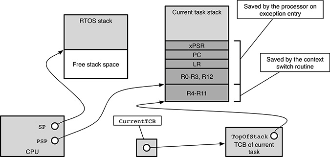
FIGURE 17.7
Detailed stack layout during a FreeRTOS context switch on the ARM Cortex-M3 architecture.
When the processor eventually honors the interrupt request, it automatically saves part of the execution context onto the task stack, namely, the program status register (xPSR), the program counter and the link register (PC and LR), as well as several other registers (R0 to R3 and R12). Then it switches to a dedicated operating system stack and starts executing the exception handling code, xPortPendSVHandler.
The handler first retrieves the task stack pointer PSP and stores it in the R0 register (line 13). This does not clobber the task context because R0 has already been saved onto the stack by hardware. Then, it puts into R2 apointer to the current TCB taken from the global variable pxCurrentTCB (lines 15–16).
The handler is now ready to finish the context save initiated by hardware by pushing onto the task stack registers R4 through R11 (line 18). At last, the task stack pointer in R0 is stored into the first field of the TCB, that is, the TopOfStack field (line 19). At this point, the stack layout is as shown in Figure 17.7, which represents the specialization of Figure 17.3 for the Cortex-M3 architecture. In particular,
the stack pointer currently used by the processor,
SP, points to the operating system stack;the
PSPregister points to where the top of the task stack was after exception entry, that is, below the part of task context saved automatically by hardware;the
TopOfStackfield of the current task TCB points to the top of the task stack after the context save has been concluded.
Going back to the listing of xPortPendSVHandler, the function now invokes the operating system scheduling algorithm, that is, the function vTaskSwitchContext (lines 21–27). To avoid race conditions, interrupt sources that may interact with FreeRTOS are disabled during the execution of this function by setting the processor base priority mask basepri appropriately. The main effect of vTaskSwitchContext is to update CurrentTCB so that it points to the TCB of the task to be executed next.
Hence, vTaskSwitchContext dereferences CurrentTCB again (line 29) to get a pointer to the new TCB. From there, it extracts the TopOfStack field and stores it into R0 (line 30). Using R0 as a stack pointer, the function pops registers R4 through R11, that is, the part of context previously saved by software, from the stack of the new task (line 31). After that, the updated stack pointer is stored into the task stack pointer register PSP (line 32).
The last step of context restoration is performed by asking the hardware to restore the remaining part of the task context, which was automatically saved on exception entry. This is done by the bx instruction at line 33. The last action also restores the task PC, and thus execution continues from where it was left off when the context was saved.
The next function to be discussed is pxPortInitialiseStack, invoked by FreeRTOS when it is creating a new task. It should initialize the new task stack so that its layout is identical to the layout of Figure 17.7, that is, the stack layout after a context save operation. In this way, task execution can be started in the most natural way, that is, by simply restoring its execution context. It takes as arguments the task stack pointer pxTopOfStack, the address from which task execution should begin pxCode, and a pointer to the task parameter block pvParameters. The return value of the function is the new value of the task pointer after the context has been saved.
 1   # define   portINITIAL_XPSR                                 ( 0 x01000000 )
 2
 3   portSTACK_TYPE * pxPortInitialiseStack(
 4      portSTACK_TYPE * pxTopOfStack ,
 5      pdTASK_CODE   pxCode , void * pvParameters      )
 6   {
 7             pxTopOfStack --;
 8             * pxTopOfStack = portINITIAL_XPSR;   /*  xPSR  */
 9             pxTopOfStack --;
10             * pxTopOfStack = ( portSTACK_TYPE        ) pxCode ;   /*  PC  */
11             pxTopOfStack --;
12             * pxTopOfStack =    0;        /*  LR  */
13             pxTopOfStack -=     5;        /*  R12, R3, R2 and R1.   */
14             * pxTopOfStack = ( portSTACK_TYPE ) pvParameters;   /*  R0  */
15             pxTopOfStack -=     8;        /*  R11, R10, R9, R8, R7, R6, R5 and R4.   */
16
17             return   pxTopOfStack;
18   }
By comparing the listing with Figure 17.7, it can be seen that the initial context is set up as follows:
The initial Processor Status Register
xPSRis the value of the macroportINITIAL_XPSR.The Program Counter
PCcomes from thepxCodeargument.The Link Register
LRis set to0so that any attempt of the task to return from its main function causes a jump to that address and can be caught.Register
R0, which holds the first (and only) argument of the task entry function, points to the task parameter blockpvParameters.The other registers are not initialized.
We have already examined the architecture-dependent functions that switch the processor from one task to another. Starting the very first task is somewhat an exception to this general behavior.
 1   void   vPortStartFirstTask(   void )
 2   {
 3             __asm   volatile (
 4                "      ldr r0 ,   =0 xE000ED08
"
 5                "      ldr r0 ,   [r0]
"
 6                "      ldr r0 ,   [r0]
"
 7                "      msr msp ,  r0
"
 8                "      svc 0
"
 9             );
10   }
11
12   void   vPortSVCHandler(   void   )
13   {
14             __asm volatile (
15                "      ldr       r3 , pxCurrentTCBConst2
"
16                "      ldr r1 ,   [r3]
"
17                "      ldr r0 ,   [r1]
"
18                "      ldmia r0!,    {r4 -r11}
"
19                "      msr psp ,  r0
"
20                "      mov r0 , #0
"
21                "      msr       basepri ,  r0
"
22                "      orr r14 , #0 xd
"
23                "      bx  r14
"
24                "
"
25                "      . align 2
"
26                " pxCurrentTCBConst2:     .word  pxCurrentTCB
"
27             );
28   }
The function vPortStartFirstTask is called by FreeRTOS to start the very first task after setting CurrentTCB to point to its TCB. It first fetches the operating system stack address from the first element of the exception vector table and stores it into MSP (lines 4–7).
In the Cortex-M3 architecture, the first 32-bit element of the exception vector table is not used as a real exception vector. It holds instead the initial value automatically loaded into the processor’s stack pointer upon reset. FreeRTOS picks it up as the top of its own stack. The actual assembly language code to retrieve this value consists of a double dereference at address 0xE000ED08. This is the address of the VTOR register that points to the base of the exception table.
It should be noted that the MSP (Main Stack Pointer) register being discussed here is not the same as the PSP (Process Stack Pointer) register we talked about earlier. The Cortex-M3 architecture, in fact, specifies two distinct stack pointers. With FreeRTOS the PSP is used when a task is running whereas the MSP is dedicated to exception handling. The processor switches between them automatically as its operating mode changes.
The initial context restoration is performed by means of a synchronous software interrupt request made by the svc instruction (line 8).
This software interrupt request is handled by the exception handler vPortSVCHandler; its code is very similar to xPortPendSVHandler, but it only restores the context of the new task pointed by CurrentTCB without saving the context of the previous task beforehand. This is correct because there is no previous task at all. As before, the processor base priority mask basepri is reset to zero (lines 20–21) to enable all interrupt sources as soon as the exception handling function ends.
Before returning from the exception with a bx instruction, the contents of the link register LR (a synonym of R14) are modified (line 22) to ensure that the processor returns to the so-called “thread mode,” regardless of what its mode was. When handling an exception, the Cortex-M3 processor automatically enters “handler mode” and starts using the dedicated operating system stack mentioned earlier.
When the execution of a task is resumed, it is therefore necessary to restore the state from that task’s stack and keep using the same task stack to continue with the execution. This is exactly what the exception return instruction does when it goes back to thread mode. A similar, automatic processor mode switch for exception handling is supported by most other modern processors, too, although the exact names given to the various execution modes may be different.
 1   # define   portNVIC_SYSTICK_LOAD      (   (  volatile unsigned long *) 0 xe000e014        )
 2   # define   portNVIC_SYSTICK_CTRL      (   (  volatile unsigned long *) 0 xe000e010        )
 3   # define   portNVIC_SYSTICK_CLK         0 x00000004
 4   # define   portNVIC_SYSTICK_INT         0 x00000002
 5   # define   portNVIC_SYSTICK_ENABLE 0 x00000001
 6
 7   void   prvSetupTimerInterrupt(   void     )
 8   {
 9             *( portNVIC_SYSTICK_LOAD)      =
10                ( configCPU_CLOCK_HZ / configTICK_RATE_HZ ) - 1UL;
11             *( portNVIC_SYSTICK_CTRL)      =
12                portNVIC_SYSTICK_CLK | portNVIC_SYSTICK_INT
13                |       portNVIC_SYSTICK_ENABLE;
14   }
15
16   void   xPortSysTickHandler(   void )
17   {
18             unsigned long ulDummy ;
19
20   #         if configUSE_PREEMPTION ==        1
21                       *( portNVIC_INT_CTRL) = portNVIC_PENDSVSET;
22   #         endif
23
24                  ulDummy =   portSET_INTERRUPT_MASK_FROM_ISR();
25                  {
26                              vTaskIncrementTick();
27                  }
28                  portCLEAR_INTERRUPT_MASK_FROM_ISR(   ulDummy );
29   }
The next two functions manage the interval timer internal to Cortex-M3 processors, also known as SYSTICK:
The function
prvSetupTimerInterruptprograms the timer to generate periodic interrupt requests at the rate specified by theconfigTICK_RATE_HZconfiguration variable and starts it.The function
xPortSysTickHandlerhandles the interrupt requests coming from the timer:If the FreeRTOS scheduler has been configured to support preemption, the function asks for a rescheduling to be performed as soon as possible (lines 20–22). Unsurprisingly, the code is identical to the body of
vPortYieldFromISR.The FreeRTOS function
vTaskIncrementTickis called, within a critical region (lines 24–28). It takes care of all aspects related to the tick timer, such as, for example, updating the current time, checking whether some task timeouts have expired, and so on.
 1   # define   portNVIC_SYSPRI2         ( (   volatile unsigned long *) 0 xe000ed20 )
 2   # define   portNVIC_PENDSV_PRI
 3      ( ( ( unsigned long     )  configKERNEL_INTERRUPT_PRIORITY ) << 16          )
 4   # define   portNVIC_SYSTICK_PRI
 5      ( ( ( unsigned long     )  configKERNEL_INTERRUPT_PRIORITY ) << 24          )
 6
 7   portBASE_TYPE xPortStartScheduler(   void )
 8   {
 9             *( portNVIC_SYSPRI2) |= portNVIC_PENDSV_PRI;
10             *( portNVIC_SYSPRI2) |= portNVIC_SYSTICK_PRI;
11
12             prvSetupTimerInterrupt();
13
14             uxCriticalNesting = 0;
15
16             vPortStartFirstTask();
17             return 0;
18   }
The very last function to be discussed here is xPortStartScheduler. It is called during FreeRTOS startup and, as its name suggests, must perform all architecture-dependent activities related to starting the scheduler. In particular,
It sets the priority of the two interrupt sources used by FreeRTOS (the
PendSVsoftware interrupt and theSYSTICKtimer) to the valueconfigKERNEL_INTERRUPT_PRIORITYtaken from the FreeRTOS configuration (lines 9–10).It initializes the
uxCriticalNestingvariable to zero. As previously discussed, this value indicates that no critical regions, based on disabling interrupts, are currently in effect.It starts the first stack, previously selected by the upper operating system layers, by calling
vPortStartFirstTask.
Under normal conditions, and as long as the operating system is running, vPortStartFirstTask never returns to the caller, and xPortStartScheduler is not expected to return, either, unless FreeRTOS is stopped completely by calling vTaskEndScheduler. However, this capability is not currently supported by the current version of the Cortex-M3 port.
17.4 Summary
Looking at how a real-time operating system, like FreeRTOS, really works inside is useful for at least two reasons:
To refine concepts such as concurrency, interprocess communication, mutual exclusion, and synchronization by filling the gap between their abstract definition and their concrete implementation. These additional details may seem tedious at a first sight but are nonetheless necessary for software developers to fully grasp them.
To better tell apart the general behavior of operating system primitives from the peculiarities and limitations of a specific operating system and API. In this way, programmers are faster and more proficient when they go from one operating system to another, and it is easier for them to produce portable code.
In this chapter we briefly explored the supporting data structures used by the FreeRTOS task scheduler and its main interprocess communication mechanism, the message queue. Then we showed that, at a closer look, even the real-world implementation of a task context switch—arguably one of the most secluded operating system mechanisms—is not as exotic as it may seem when the concept is contemplated from far away.
A short discussion of how a simple operating system can be ported from one architecture to another, and what an HAL must contain, concluded the chapter. Due to lack of space, the presentation is far from being exhaustive but can be used as a starting point for readers willing to adapt an operating system to the hardware architecture they are working on.