
Innovative Systems for Storage of Thermal Solar Energy in Buildings
Lingai Luo1; Nolwenn Le Pierrès2 1 Laboratoire de Thermocinétique de Nantes (LTN-CNRS UMR 6607), La Chantrerie, Nantes Cedex, France
2 LOCIE, CNRS UMR 5271-Université de Savoie, Polytech Annecy-Chambéry, Campus Scientifique, Savoie Technolac, Le Bourget-Du-Lac Cedex, France
Abstract
This chapter presents the thermal energy storage technologies suitable for low temperature (up to 150 °C) solar thermal applications in buildings. In the first part, insight is provided into recent developments about systems technologies and materials, their classification, limitations, and potential solutions for their application. In the second part, special focus is given on an innovative process using absorption cycles for long-term solar energy storage. A detailed dynamic model of the system has been developed for the simulation in order to evaluate the process performance and to optimize its design. A prototype of the system has also been presented, as well as experimental results in the process charging and discharging modes.
Nomenclature
Notations
A area (m2)
Cp specific heat (J kg− 1 °C− 1)
h specific enthalpy (J kg− 1)
Δhcr specific enthalpy of solution of LiBr·2H2O (J kg− 1)
k mass fraction of anhydrous LiBr in the crystal hydrate
LiBr lithium bromide
m mass flow rate (kg s− 1)
m% mass percent
M mass (kg)
MLiBr mass of anhydrous LiBr (kg)
P pressure (Pa)
q heat (J)
Q power (W)
SHX solution heat exchanger
t time (s)
T temperature (°C)
Ttank ambient temperature around the storage tanks (°C)
U heat transfer coefficient (W m− 2 °C− 1)
v volume flow (m3 s− 1)
w work (W)
x mass fraction of lithium bromide in the solution (m%)
Greek Symbols
α absorption percentage
η efficiency
ρ density (kg m− 3)
Indices
b building
c condenser external loop fluid
cr crystal
end end of the process
eq equilibrium conditions
ext exterior (outside)
g generator external loop fluid
i inlet
ini beginning of the process
int interior (building)
is isentropic
liq liquid
loss loss
max maximum
o outlet
p propylene glycol
ref surrounding
sh tank shell
shext external side of the tank shell
shint internal side of the tank shell
sol solution
v vapor phase
w water
1 solution storage
2 generator
3 condenser or evaporator
4 water storage
1 → 2 tube connecting 1-2
' value from previous time step
3.1 Introduction
With the diminishing reserves of fossil fuels, the increasing energy demand, and the greenhouse gas emissions rise, energy consumption is at a critical stake. Developing more energy-efficient and environmentally friendly devices is essential to reach the “3E” objectives, conciliating clean environment, sustainable energy policy, solid economy, and social development.
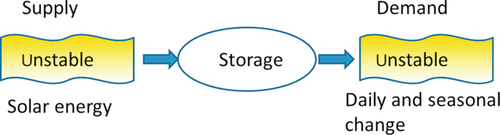
The main role of storage systems is to reduce the time or rate mismatch between supply and demand (Figure 3.1). Solar energy seems to be the most promising renewable energy source (Goswami et al., 2000; Asif and Muneer, 2007). However, its intermittent and unstable nature is a major drawback, which leads to a disparity between supply and demand. Some of its fluctuations are predictable (day/night, season), but some are unpredictable (weather effect). Energy storage is an appropriate method of correcting these disparities. To enhance the fraction of energy use and make solar systems more efficient, practical, and attractive, heat storage systems are perceived as crucial components in solar energy applications.
Methods of solar thermal energy storage are mainly divided into three types: sensible, latent, and sorption/thermochemical (Hadorn, 2008; Odru, 2010).
Sensible and latent thermal storage have been the most studied technologies in the past decades. Most thermal storage devices used in practical solar systems involve sensible or latent storage methods. For sensible storage, heat is stored by the temperature difference of the storage medium; the value of its storage density depends on its specific heat and the temperature change.
In the latent thermal storage method, heat is stored through the phase change of a material at a relatively constant temperature. The materials are often referred to as phase change materials (PCMs). Compared to sensible thermal storage, latent heat storage has higher storage density and a much smaller temperature change; but it still involves important drawbacks, such as long-term stability of storage properties, low thermal conductivity, phase segregation, and subcooling during the phase change process (Farid et al., 2004).
Thermochemical storage can be divided into chemical reaction and sorption. Large amounts of heat can be stored in such processes (Figure 3.2), where heat is stored by breaking the binding force between the sorbent and the sorbate in terms of chemical potential.

The choice criteria for the type of storage to select are numerous, and often lead to a contradictory optimum system and material:
– High energy density of the storage (kWh m− 3)
– High heat delivery power (good transfer between the heat transfer fluid (HTF) and the storage medium)
– Mechanical, thermal, and chemical stability of the storage material
– Chemical compatibility between storage material, heat exchanger, and storage medium
– Complete reversibility for a large number of charging/discharging cycles
– Easy integration in the user's system
– Low thermal losses
– Low cost (low price per kWh of heat stored)
– Low environmental impact
In this chapter, the aforementioned three different solar heat storage systems in buildings will be presented. This chapter provides insight into recent developments about systems technologies and materials, their classification, limitations, and potential solutions for their application. According to the building needs, only the heat storage processes involving temperature levels between the ambient and 150 °C are considered. High temperature solar heat can also be stored, as discussed in Gil et al. (2010).
3.2 Major Technologies for Heat Storage in Buildings
3.2.1 Sensible Storage
One definition of sensible heat storage materials is that of materials that undergo no phase change in the temperature change of the heat storage process (Fernandez et al., 2010). The amount of energy q involved in a sensible heat storage process depends, as presented in Equation (3.1), on the specific heat of the material (Cp(T)), the temperature change (Tf, Ti), and the amount (M) of material.
Some disadvantages are inherent to sensible heat storage systems. The most important of them are their relatively low energy density and the self-discharge (heat losses) of the system, which can be important particularly when long periods of storage are the aim.
Sensible heat storage in buildings has been widely investigated throughout the literature and can be divided into two groups: liquid and solid storage mediums. Liquids are most often limited to water for this application, and solids are rocks, bricks, concrete, iron, dry and wet earth, and many others.
3.2.1.1 Liquid Storage
Water has been widely used for heat storage as well as for heat transport purposes in energy systems. It appears to be the best of sensible heat storage liquids for temperatures lower than 100 °C because of its availability, its inexpensiveness and, most important, its relatively high specific heat (Fath, 1998). For a 70 °C temperature change (from 20 to 90 °C), water can store 290 MJ m− 3. Today, it is also the most widely used storage medium for solar-based warm water and space heating applications. There exists a large amount of published data on the design criteria for systems with water as a heat storage material (Garg et al., 1985; Abhat, 1980; Duffie and Beckman, 1989; Wyman et al., 1980).
3.2.1.2 Solid Storage
Solid media are widely used for low temperature storage. They usually consist of rocks, concrete, sand, bricks, and so on. Materials most commonly in use in buildings for solar heat storage are indeed the ones involved in the building structure, rock beds, and in borehole thermal storage. For solar heat storage in building applications, solid materials are mostly used for space heating and cooling (air conditioning) purposes. Their operating temperatures cover a wide range, from 10 to over 70 °C. The major drawback of using solids as heat storage materials is their low specific heat capacity (~ 1200 kJ m− 3 K− 1 in average), which results in a relatively low energy density (more than three times less energy stored than water in the same volume for the same temperature lift, for example). However, compared to liquid materials, two main advantages are inherent to solids materials: their viability at higher temperatures, and no leakage problem with their containment (Hasnain, 1998). The compatibility of the material with the HTF used is of importance (Fath, 1998). Also, the efficiency and the viability of heat storage systems with solid materials is strongly dependent on the solid material size and shape, the packing density, the type of HTF, the flow pattern, and so on.
3.2.2 Latent Heat Storage
By definition, latent heat storage is based on the heat absorbed or released when a material undergoes a phase change from one physical state to another. Practically, the phase change can occur through the following forms: solid-solid, solid-liquid, solid-gas, liquid-gas, and vice versa.
During the solid-solid transitions, heat is stored as the material is transformed from one crystalline form to another (Sharma et al., 2009). Due to the fact that there is just a change of the crystalline structure, small latent heat and small volume changes are generally observed in comparison to solid-liquid transitions. In return, solid-solid PCMs have the advantages of less stringent container requirements and greater design flexibility (Pillai and Brinkwarth, 1976). During the past decades, relatively few solid-solid PCMs that might have a heat of fusion and transition temperatures suitable for low temperature solar applications have been identified. One of the most promising is pentaglycerine (melting temperature 81 °C, latent heat of fusion 263 MJ m− 3) (Garg et al., 1985).
Solid-gas and liquid-gas transitions present higher latent heat, but the large volume change involved during the transition leads to more stringent containment requirements; they cannot be suitable for solar heat storage applications (Hasnain, 1998).
Solid-liquid PCMs have benefited from many developments during the two last decades, although the amount of heat involved during their phase change is comparatively smaller than that of solid-gas or liquid-gas PCMs. Solid-liquid PCMs can store and release a relatively large quantity of heat over a narrow temperature range, without a large volume change. Solid-liquid transitions have also proved economically attractive (Hasnain, 1998).
Globally, latent heat storage systems have some advantages on sensible heat storage systems. They are volumetric heat storage density, which is high; and operating temperature, which is relatively constant for PCM systems but can vary widely for sensible systems, corresponding to the load. As shown in Table 3.1, for the same amount of heat stored, latent heat storage systems using paraffin wax will need 1.5 times (or 3 times) less volume than sensible heat storage systems using water (or rocks), with a 50 °C temperature change. But there are some disadvantages associated with latent heat storage materials. Low thermal conductivity, material stability over several cycles, phase segregation, subcooling, and cost are some of the limitations that are currently under investigation (Dincer and Rosen, 2002; Farid et al., 2004; Sharma et al., 2009).
Table 3.1
Comparison of Various Heat Storage Media (For Sensible Storage Materials, Energy is Stored in the Temperature Range 25-75 °C) (Tatsidjodoung et al., 2013)
| Property | Heat Storage Material | |||
| Sensible Heat Storage | Phase Change Materials | |||
| Rock | Water | Paraffin Wax | CaCl2·6H2O | |
| Latent heat of fusion (kJ kg− 1) | a | a | 174.4 | 266 |
| Specific heat capacity (kJ kg− 1 K− 1) | 0.9 | 4.18 | b | b |
| Density (kg m− 3) at 24 °C | 2240 | 1000 | 1802 | 795 |
| Storage volume for storing 1 GJ (m3) | 9.9 | 4.8 | 3.2 | 4.7 |
| Relative volumec | 3.1 | 1.5 | 1.0 | 1.5 |

a Latent heat of fusion is not of interest for sensible heat storage.
b Specific heat capacity is not of interest for latent heat storage.
c Equivalent storage volume; reference taken on paraffin.
PCMs can be classified into the following major categories: inorganic PCMs, organic PCMs, and eutectic PCMs. Each of these groups can be further categorized into more detailed subgroups, as shown in Figure 3.3. Each of these groups has its typical range of melting temperature and melting enthalpy.

3.2.2.1 Inorganic PCMs
Inorganic PCMs are constituted of salt hydrates and metals.
Salts hydrates have been the most investigated for heat storage purposes at low temperatures. Salt hydrates can be considered alloys of inorganic salts (AB) and water (H2O), resulting in a typical crystalline solid of general formula (AB·xH2O) (Sharma et al., 2009). Their phase change transition can actually be regarded as a dehydration or hydration of the salt, although this process can be assimilated to a melting or a freezing of the compound. Salt hydrates usually melt to either a salt hydrate with fewer moles of water, or to its anhydrous form. During the phase change transition, liquid water released from the hydrated salt dissolves the formed nonhydrated salt molecules.
Most of the selected metals with low melting temperature as members of the group of inorganic PCMs are fusible alloys of bismuth with other metals such as lead, tin, indium, and cadmium. As a general rule, the physical properties of these alloys will be close to those of bismuth, with some differences linked to the addition of the other compounds. Some important drawbacks of metals as energy storage media are their scarce availability and their high cost. However, when volume is a constraint, they are good candidates because of their high volumetric heat of fusion. Another advantage of these materials over other PCMs is their high thermal conductivity.
3.2.2.2 Organic PCMs
Organic heat storage materials are usually separated into two groups: paraffins and nonparaffin organic materials.
Paraffins can be defined as a mixture of pure alkanes, mostly straight chain configured. The crystallization/fusion of their molecular chain involves a large amount of latent heat. They are usually referred to as “paraffin waxes,” with the chemical formula CnH2n + 2, where 20 ≤ n ≤ 40. The average heat of fusion of paraffins is 170 MJ m− 3, and is almost half the value of that of hydrated salts.
Nonparaffin organic PCMs are constituted of compounds such as fatty acids, esters, and alcohols (Hasnain, 1998; Sharma et al., 2009). They are highly flammable and therefore should not be exposed to intense temperature, flames, and oxidizing agents. It is the main drawback for their use as heat storage materials. Other features of these organic materials are reproducible melting and freezing behavior, freezing with no supercooling, low thermal conductivity, and varying level of toxicity. Their volumetric heat of fusion is comparable to that of paraffins.
3.2.2.3 Eutectics
Eutectics are alloys of inorganics (mostly hydrated salts) and/or organics. They have a single melting temperature, which is usually lower than that of any of the constitutive compounds. Eutectics form one single common crystal when crystallized (Hasnain, 1998). One of the most important characteristics of eutectics is their capability to melt/freeze congruently without phase segregation. A large number of eutectics have been reported throughout the literature and classified as inorganic, organic, and organic-inorganic eutectics. Organic eutectics have in general a lower melting temperature and a greater heat of fusion than inorganic eutectics do, making them adequate for low-temperature solar heat storage needs.
3.2.3 Sorption Heat Storage Systems
Sorption technologies, which used to be considered mainly for cooling and heat pumping, have gained a lot of interest for heat storage purpose in recent years, due to their high energy densities and long-term storage efficiency. Sorption heat storage is separated into four technologies: liquid absorption, solid adsorption, chemical reaction, and composite materials. After a general presentation of the different possible processes and the operating principle, we will illustrate an innovative technology: an absorption solar heat storage system.
3.2.3.1 Process Classification
Sorption technologies involve two chemical compounds: a sorbate and a sorbent. Sorbent/sorbate is called the “sorption couple.” Depending on the link between the sorbent and the sorbate and the state of the sorbent, sorption can be divided into two types: solid/gas and liquid/gas (Figure 3.4). Moreover, based on the cohesive force between the two phases, adsorption is further divided into two types: physical adsorption (physisorption) and chemical adsorption (chemisorption) (N'Tsoukpoe et al., 2009).

Physical adsorption is a general phenomenon that occurs whenever an adsorbate is brought into contact with the surface of the adsorbent. The forces involved are intermolecular forces (van der Waals forces). Chemical adsorption is due to covalent forces. The main difference between the two kinds of sorptions is the magnitude of the heat of adsorption (Yu et al., 2013). Because chemical forces are stronger than physical forces, heat of chemical sorption is usually larger than heat of physical sorption. Though this helps in recognizing physical and chemical adsorptions, in some cases it can be unclear which kind of adsorption (or both) is involved.
The word “absorption” is used when the molecules of the sorbate penetrate the surface layer and enter the structure of the bulk solid/liquid sorbent, causing the change of the composition of one or both bulk phases. Liquid absorption working pairs have been used in absorption chillers and heat pumps for decades.
3.2.3.2 Storage Operating Principle
The mechanism of heat storage through a sorption process can be represented by the following equation (Yu et al., 2013):
Here, A is the sorbent and B is the sorbate. For a chemical reaction process, A·(i + j)B and A·iB mean a compound of one mole of A with (i + j) mole of B and i mole of B, respectively. For a liquid absorption process, A·(i + j)B represents a solution with a lower concentration of A than A·iB. For a solid adsorption process, A·(i + j)B represents the enrichment of B on the surface of A, as j more mole of B is adsorbed.
During the endothermal charging process (direct sense of Equation (3.2)), when heat is added to A·(i + j)B, the binding force between A and B is broken and some B is separated from A. Energy is stored in terms of the chemical potential ΔHs (J mol− 1). During the exothermal discharging process (indirect sense of Equation (3.2)), A·iB is brought into contact with j mole of B to form A·(i + j)B again, and the heat ΔHs is released.
3.3 Focus on a Solar Heat Absorption Storage System
To illustrate the most innovative storage technology, an example of one of the possible sorption processes will be detailed: an absorption solar heat storage system.
3.3.1 Basic Cycle Description
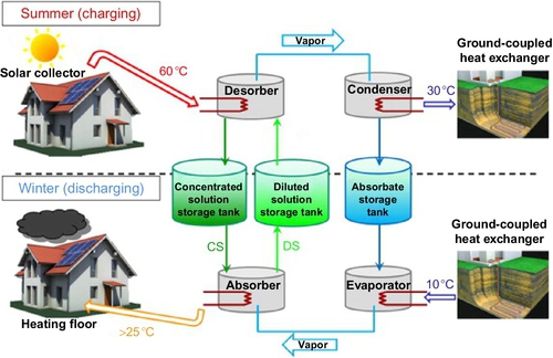
Liu et al. (2011) proposed a long-term solar heat storage absorption cycle for building heating. Figure 3.5 gives the operation principle of the system. The charging of solar energy takes place during summer and heat is released during winter. Comparative to heat sorption cooling systems, this process can be developed with only two heat exchangers that work reversely in the two functioning phases: a desorber in the charging phase that works as an absorber during the discharging phase, and a condenser in the charging phase that works as an evaporator during the discharging phase. The other originality of this cycle is the fact that it allows the solution to reach the crystallization point in the storage tank. Figure 3.6 describes the working principle of this cycle, using the LiBr/H2O sorption couple as an example. The high pressure (HP) level and low pressure (LP) level depend on the condensation temperature (point C) in summer and the evaporation temperature (point E) in winter, respectively. From point 2 to point 3 or 3′, solar heat is continually transferred from solar collectors to heat the solution (charging phase in Figure 3.5). The absorbate is driven out of the LiBr solution and transferred to the condenser. The strong solution at point 3 or 3′ flows back to the storage tank. Line 3-5 or 3′-5 represents the transition storage period during the summer to the winter, when the solution is kept in the tank and separated from other vessels. In winter, the absorbate is evaporated and then absorbed by the solution at point 5-7 (Figure 3.6 and discharging phase in Figure 3.5). Cycle 1-2-3-5-6-7-1 refers to a conventional long-term absorption storage cycle, in which point 3 should be carefully chosen to avoid the formation of crystal from point 3 to point 5. For the cycle 1-2-3′-4-5-6-7-1, the mass fraction of the solution at point 3′ can be higher than that at point 3. The solid crystal form of the salt is allowed to appear during the transition period in the solution tank. This improvement greatly enhances the storage density of the solution because of the increase of the interval of mass fraction between the weak and strong solutions, as will be explained in Section 3.3.2.3.

3.3.2 Process Modeling and Simulations
In order to evaluate the system performances (storage density, thermal and electrical efficiencies, required collector area, etc.) and identify the parameters that influence significantly these performances, a model has been developed for dynamic simulations of the process (N'Tsoukpoe et al., 2012). This model considers the transient characteristics of the system, inherent in the operating conditions of the process that change year-round: daily variations of the solar radiation, the environment (heat sink or source) and the building heating demand, variation of solution concentration in the storage, crystal formation, and so on. Thermal loss to the ambient, walls' thermal inertia, heat and mass transfer limitations in various components, and the energy consumption by auxiliary equipment (especially circulating pumps) are also considered.
3.3.2.1 System Modeling
The model is based on the energy and mass balance equations and the properties of the LiBr/H2O couple (Saul and Wagner, 1987; Hellmann and Grossman, 1996). The main inputs of the model are the heat absorbed by solar collectors, the ambient temperature and the heating demand, the flow rate of the solution and water, and the overall heat transfer coefficients UA of the heat exchangers. The model calculates the system variables, such as the components' pressures and temperatures, the solution concentration in the generator and the solution tank, the mass of water in the water tank, the mass of solution and of crystal of LiBr hydrate in the solution storage, the circulating pumps' consumption, heat losses to the ambient, and so on. The details of this model can also be found in N'Tsoukpoe et al. (2012).
3.3.2.1.1 Generator
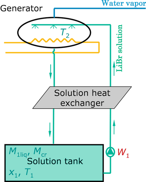
The internal temperature T2 in the generator is assumed to be uniform (Figure 3.7) even if it varies along the heat exchanger due to the variation of the concentration of the solution (Patnaik et al., 1993). As in most studies on absorption systems and supported by various experiments, the generator model is based on heat transfer (Banasiak and Koziol, 2009). The power exchanged by the generator internal (solution) and external flows is evaluated by using the logarithmic mean temperature difference approach. The modeling rests on the assumption that the values of the overall heat transfer coefficient of the generator heat exchanger (UA)2 are constant. Actually, the values of UA vary somewhat with the temperature as well as with the mass flows, but this variation is relatively small in most cases (Patnaik et al., 1993; Grossman et al., 1995). The exchanged heat in the generator is therefore


Equations (3.4) and (3.5) are solved to estimate the generator heat losses to the ambient, assuming that the generator shell is isothermal. Equation (3.4) expresses the generator shell internal energy variation, which is the difference between the internal heat received by convection and the external one.

In order to take into account the fact that the solution leaving the generator is not in equilibrium conditions, a mass transfer effectiveness α, also called absorption percentage or absorption equilibrium factor (Andberg and Vliet, 1983; Kaushik et al., 1985; George and Murthy, 1989; Patnaik et al., 1993), is introduced in Equation (3.9). The absorption percentage is the ratio of the actual change in concentration of the solution to the maximum possible change that could be obtained with an infinitely long plate. The maximum possible change is the difference between the generator inlet concentration and the equilibrium concentration.
Mass and energy balances in the generator yield Equations (3.6)–(3.15):
3.3.2.1.2 Condenser/Evaporator
The modeling of the condenser is similar to that of the generator. It is added to the previous assumptions that the amount of water vapor desorbed in the generator is completely condensed in the condenser. Conversely, all the water vapor produced in the evaporator is absorbed by the solution in the absorber.
3.3.2.1.3 Solution Tank
The tank model is based on global mass and energy balances. The solution tank is then assumed to be well mixed (temperature and concentration), and the mass of solution accumulated in the other components of the process is neglected in comparison to the mass of solution in the storage tank. Crystals are considered to be in equilibrium with the saturated solution when they appear. The following equations apply:

3.3.2.1.4 Water Tank
Assumptions in the water tank modeling are the same as in the case of the solution tank, except that there is no crystal:
3.3.2.1.5 Connection Tubes
The evaluation of the heat losses of tubes that connect the process components is made, granted that the specific heat of the fluid in the tube is constant along the tube. Equations (3.37) and (3.38), for example, give the heat losses to the ambient for the connection tube between the generator 2 and the solution tank 1.
3.3.2.1.6 Circulating Pumps
The energy transferred to the solution and water by the circulating pumps (W1 and W2) is estimated by considering an isentropic efficiency ηis for each pump, and the fact that the density of the liquid is constant between the tank outlet and the heat exchanger inlet. Thus, Equation (3.39) gives the work w1 provided by circulating pump W1 to the solution.
A value of 0.8, which is relatively low, is used as the isentropic efficiency of the pumps, as its influence is low on the system performances.
3.3.2.1.7 Environment: Heat Sink/Low-Temperature Heat Source
Simplified models for the condenser heat sink (charging period) and the evaporator low-temperature heat source (discharging period) are introduced. The temperature of the cooling fluid at the entrance of the condenser Tci is set to 3 °C below the outdoor air temperature when the latter is higher than 10 °C; otherwise, Tci is set to 5 °C. The HTF temperature entering the evaporator is constant and equal to 10 °C.
3.3.2.2 Inputs and Assumptions of the Simulations
The main input data of the model are the meteorological data and building heating need. Solar radiation and outdoor air temperatures measured during 2005 in Chambéry, in the alpine region of France, are used. To evaluate the heating need, a simplified method is applied. The heating need given by Equation (3.40) is estimated by considering an overall heat loss coefficient for the building and a base temperature Text of 10 °C.
The comfort temperature Tint is set to 20 °C at daytime and 16 °C at nighttime.
Simulations have been performed for a single-family house of 120 m2 that meets passive house standards in order to achieve 100% solar fraction. Its annual heating need is about 1800 kWh, with a peak heat load of 1.2 kW.
The generator inlet temperature is limited to 90 °C in order to limit crystallization risk in the generator. Storage tanks are presumed to be buried underground or put in a basement, where the ambient temperature Ttank is assumed constant at 5 °C. As for the condenser and the generator, they are in a nonheated space where the temperature Tref is also supposed to be constant at 15 °C.
3.3.2.3 Simulation Results
The process performances are strongly influenced by the operating conditions and the process design. The numerical model can be used to identify the parameters that have major impacts on the key performance indicators of the system: storage density and thermal efficiency.
3.3.2.3.1 Effects of the Heat Exchanger Sizes
The generator and condenser overall heat transfer coefficients UAg and UAc respectively were varied from 0.2 to 0.8 kW K− 1, and results are reported in Figure 3.8. This UA range is chosen based on the power (< 2 kW) necessary to cover the passive house needs. The storage density can be improved by about 60% when increasing the heat exchanger performance within the considered UA range. This is due to a lower minimum concentration of the cycle (points 1 and 2 in Figure 3.6). Indeed, the smaller temperature difference between the heat exchanger sides for high UA values for a given power has two consequences on the cycle. One is that the evaporator temperature increases (point E in Figure 3.6). The other is that the required absorber temperature is lower (points 6-7 in Figure 3.6).
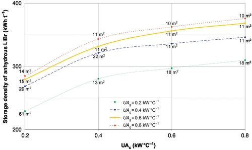
The required solar thermal collector area also decreases when the UA value increases (Figure 3.8) because desorption is more efficient. This is due to a higher generator temperature and lower condenser temperature on average. For very low UA values (for both UAg = UAc = 0.2 kW K− 1 in the present case), the system performance drops sharply.
Further simulations with a solution heat exchanger (SHX) between the solution tank and the generator (Figure 3.9) show that it strongly improves the process thermal efficiency and its storage density. However, this SHX could lead to technical issues (crystal formation and tube clogging), as will be discussed in Section 3.3.3.
3.3.2.3.2 Effects of the Absorption Percentage
The effect of the absorption percentage on the storage density is also studied. The requirements to reach a mean heat supply temperature of 30 °C and a maximum crystallization ratio of 67% are summarized in Table 3.2. The storage density decreases with a low absorption percentage. Indeed, the solution temperature in the absorber is lower than the equilibrium temperature. Thus, a higher minimum concentration of the cycle is needed. Similarly, during desorption, with low absorption percentage, the generator outlet bulk concentration is lower than the interface concentration, so that the actual amount of generated water is lower than in equilibrium conditions. There are then greater sensible heat losses and greater heat needs for desorption, which result in a larger solar collector area.
Table 3.2
Main Simulation Parameters and Results for Various Absorption Percentages (N'Tsoukpoe et al., 2012)
| Simulation No. | 9 | 10 | 11 | 12 | 13 | 14 |
| Absorption percentage α | 0.75 | 0.80 | 0.85 | 0.90 | 0.95 | 1.00 |
| Solution minimum concentration in the storage tank (m%) | 52.7 | 52.1 | 51.7 | 51.1 | 50.7 | 50.4 |
| Surface area of flat solar collectors (m2) | 16 | 15 | 15 | 13 | 13 | 13 |
| Storage density of anhydrous LiBr salt (kWh t− 1) | 269 | 281 | 292 | 300 | 312 | 321 |
| Storage density of LiBr aqueous solution (kWh m− 3) | 226 | 233 | 239 | 241 | 247 | 252 |
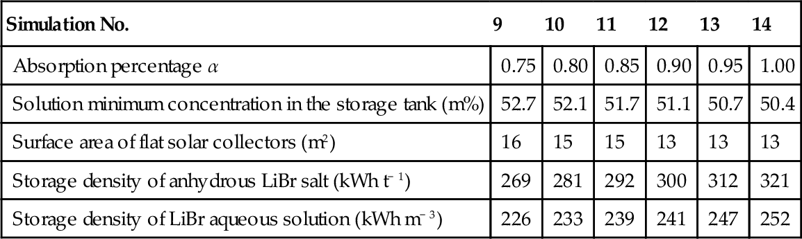
Special attention should thus be paid to the generator design, because the absorption percentage depends on the exchanger design and the solution flow rate.
3.3.2.3.3 Effects of the Maximum Crystallization Ratio
Figure 3.10 shows the storage density as a function of the maximum crystallization ratio at average heat supply temperatures of 30 °C and 33 °C. Crystallization can increase the storage density more than three times. However, above a maximum crystallization ratio of 70%, savings become less and less significant, while the technical complexity of the process increases. Thus, a compromise has to be made for the choice of the optimal crystallization ratio.

3.3.3 Process Experimentations
This process has been tested and the feasibility of the crystal formation and dissolution in the solution tank has been proven, as well as the possibility to store and produce heat at the desired temperature levels (N'Tsoukpoe et al., 2013, 2014).
3.3.3.1 Prototype Design
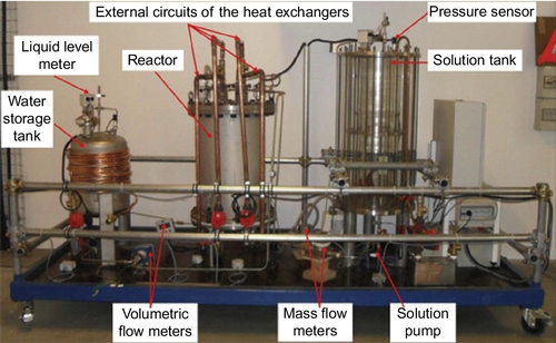
A demonstration prototype has been designed, which could theoretically store 8 kWh of heat and produce a heating power of 1 kW. This prototype for demonstration of the feasibility of the concept has been built as shown in Figure 3.11. It mainly consists of two storage tanks and a reactor containing two heat exchangers.
Two identical vertical falling film heat exchangers (shell-and-tubes) have been chosen (Figure 3.12, Table 3.3). This type of exchanger is compact compared to some related technologies and is most frequently used in absorption machines, as it is seen to be most appropriate because of its small pressure losses (Fujita, 1993; Jani et al., 2004; Bo et al., 2010). Furthermore, it is suitable for processes with low-temperature heat sources, such as solar energy, as they offer high heat transfer coefficients. In the charging phase, the water desorption and condensation take place inside the tubes when the HTF flows on the shell side (Figure 3.12b). Similarly, absorption and evaporation take place on the tube side. These tubes are in brass aluminum (CuZn22Al2), which is a copper alloy particularly renowned for its resistance to corrosion. Indeed, LiBr aqueous solution is particularly corrosive (Behrens et al., 1992; Arnaud et al., 1985; Herold et al., 1996; Florides et al., 2003). A radiation shield (Figure 3.12a) has been installed in the reactor in order to reduce direct heat exchanges between the two heat exchangers. Under each heat exchanger, a collector receives the liquid leaving the heat exchanger before it is pumped into the corresponding storage tank.
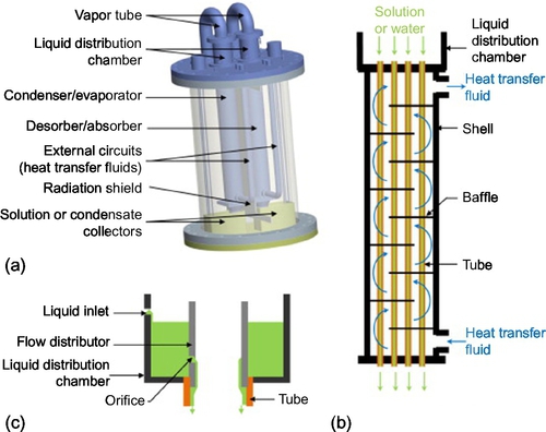
Table 3.3
Main Features of Each Heat Exchanger (Total Internal Surface of Tubes: A = 0.33 m2) (N'Tsoukpoe et al., 2013)
| Value | |
| Length of a tube (mm) | 620 |
| Inside diameter of tubes (mm) | 12 |
| Number of tubes | 14 |
| Number of orifices per tube | 3 |
| Diameter of each orifice (mm) | 0.4 |
Four pumps ensure fluid circulation (solution and absorbate) between the components (Figures 3.11 and 3.13). They are of the gear type and magnetically coupled so that seal leaks are normally not possible. To avoid obstruction in the outlet tube of the solution storage tank when crystallization occurs, the solution is pumped near its surface (upper part of the tank). This is achieved by a floating intake with a spiral tube that is connected to the solution pump (Figure 3.13). The desorber/absorber outlet enters the solution storage tank at its bottom in order to favor mixing in the tank. The components are connected with stainless steel tubes.

The water storage tank is made of stainless steel (316 L), whereas the solution storage tank is a glass column (Figure 3.11). This allows observing the crystallization in this tank and possibly other phenomena such as convection or stratification in concentration. The storage tank environment temperature is set through heat exchanges around the tank surfaces (Figure 3.13). Each heat exchanger is connected to a thermal module that can provide the assigned temperature and flow rate, either in static or dynamic operating mode.
Ultra-Torr vacuum fittings from Swagelok are used to ensure vacuum tightness of the prototype. Where necessary, a sealant tape (LSM1310 provided by DIATEX) is added.
3.3.3.2 Measurements and Experimental Procedure
The prototype has been strongly instrumented (Figure 3.13) to be able to measure temperatures (accuracy: ± 0.2 °C), pressures (± 0.25 mbar), mass flow rates (± 0.05% for the solution and ± 0.1% for the HTF in external circuits), volume flows (± 1 l h− 1), and liquid levels inside the components (± 2 mm). The solution mass flow rates are measured by Coriolis flowmeters that also measure temperature (± 0.2 °C) and density (± 1 kg m− 3). The solution concentration at the desorber inlet/outlet is derived from these measurements, using a correlation between the solution concentration, temperature, and density (Lee et al., 1990). The prototype is computer-monitored and controlled using a Labview® program.
Experiments are carried out under static and dynamic conditions. The desorber HTF flow rates, the solution flow rates, the condenser and desorber HTF inlet temperatures, as well as storage tanks' surrounding temperatures are selected as values that can be reached under a French climate for a passive house equipped with flat solar collectors and a geothermal pipe.
The initial solution prepared and introduced in the solution storage tank contains 46 kg of anhydrous LiBr and 42.5 kg of water. This means an initial concentration of 52 m%.
Preliminary tests indicate that the solution distributors at the top of the tubes of the desorber do not operate as expected and seem to be undersized: the solution is distributed mainly by overflow weirs at the top of the tubes instead of the orifices intended for this (Figure 3.12c). This is known to give very bad liquid distribution (dry patch, flooding, etc.) and lead to bad heat and mass transfers (Whalley, 1978a,b).
3.3.3.3 Experimental Results and Discussion in Charging Mode
In this section, a summary of all the results of charging tests is given and discussed.
Table 3.4 presents the main results of the charging tests (experimental design and additional tests) in chronological order.
Table 3.4
Charging Test Results (N'Tsoukpoe et al., 2013)
| Test No. | 1 | 2 | 17 | 18 | 3 | 4 | 5 | 6 | 7 | 8 | 19 |
| Date | 02-Sep | 02-Sep | 02-Sep | 13-Sep | 13-Sep | 15-Sep | 15-Sep | 16-Sep | 19-Sep | 19-Sep | 21-Sep |
| Start of the test (h:min) | 09:23 | 13:50 | 17:50 | 11:30 | 14:57 | 10:43 | 13:07 | 09:28 | 09:50 | 12:04 | 10:00 |
| End of the test (h:min) | 13:30 | 17:50 | 19:00 | 14:39 | 16:01 | 13:02 | 15:33 | 11:31 | 11:50 | 14:07 | 14:30 |
| Duration (h:min) | 04:07 | 04:00 | 01:10 | 03:09 | 01:04 | 02:19 | 02:26 | 02:03 | 02:00 | 02:03 | 04:30 |
| Solution initial concentration (m%) | 52.2 | 54.8 | 56.9 | 53.3 | 56.5 | 53.8 | 54.9 | 56.0 | 54.9 | 56.3 | 54.9 |
| Solution final concentration (m%) | 54.7 | 56.9 | 59.5 | 55.7 | 57.7 | 54.9 | 56.0 | 57.1 | 56.3 | 58.1 | 57.4 |
| Desorber inlet HTF temperature (°C) | 90.0 | 90.0 | 90.0 | 90.0 | 89.6 | 75.0 | 75.3 | 88.9 | 75.0 | 75.3 | - |
| Condenser inlet HTF temperature (°C) | 20.1 | 10.1 | 10.1 | 30.1 | 10.1 | 20.1 | 20.1 | 20.1 | 10.2 | 10.2 | 20.1 |
| Desorber HTF flow rate (kg h− 1) | 360 | 720 | 720 | 720 | 360 | 360 | 720 | 720 | 360 | 720 | 360 |
| Condenser HTF flow rate (kg h− 1) | 360 | 720 | 720 | 720 | 720 | 720 | 720 | 360 | 360 | 360 | 360 |
| Solution flow rate (l h− 1) | 38.2 | 38.2 | 18.3 | 41.1 | 24.1 | 44.5 | 21.7 | 22.0 | 22.7 | 43.5 | 22.5 |
| Mass of desorbed water (kg) | 5.4 | 4.1 | 1.3 | 4.4 | 2.0 | 3 | 2.3 | 2.2 | 2.4 | 3.1 | 4.0 |
| Mass rate of desorbed water (kg h− 1) | 1.31 | 1.02 | 1.13 | 1.39 | 1.89 | 1.30 | 0.95 | 1.01 | 1.18 | 1.49 | 0.89 |
| Average desorber heat transfer coefficient (W °C− 1) | 78 | 74 | 64 | 138 | 72 | 145 | 81 | 72 | 75 | 126 | 75 |
| Average equilibrium factor | 0.46 | 0.25 | 0.92 | 1.00 | 0.73 | 0.28 | 1.25 | 0.80 | 0.70 | 0.35 | 0.57 |
| Average power of the desorber (kW) | 2.3 | 2.2 | 1.7 | 3.0 | 2.2 | 2.4 | 1.5 | 2.0 | 1.8 | 2.4 | 1.6 |
| Average power of the condenser (kW) | − 0.9 | − 1.1 | − 1.0 | − 1.1 | − 1.5 | − 0.8 | − 0.7 | − 0.8 | − 0.9 | − 1.0 | − 0.7 |
| Total exchanged energy in the desorber (kWh) | 9.5 | 8.7 | 1.7 | 9.4 | 2.4 | 5.5 | 3.6 | 3.6 | 3.6 | 4.9 | 8.1 |
| Total exchanged energy in the condenser (kWh) | − 3.8 | − 4.2 | − 0.9 | − 3.5 | − 1.6 | − 1.9 | − 1.8 | − 1.6 | − 1.7 | − 2.1 | − 3.2 |
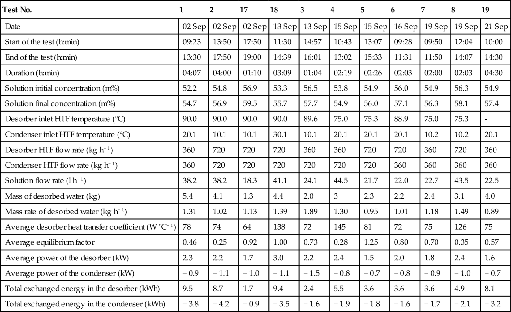
Three values (measured or derived quantities) are considered most important:
– The water desorption rate or the mass transfer in the desorber: the amount of desorbed water is an indicator of the amount of stored energy and is therefore considered the most important response
– The average heat transfer in the desorber: the heat exchanger performance analysis is important because it strongly affects the process storage density (N'Tsoukpoe et al., 2012)
– The equilibrium factor: as previously stated (Equation (3.9)), it indicates the mass transfer effectiveness in the reactor (N'Tsoukpoe et al., 2012)
3.3.3.3.1 The Water Desorption Rate in the Desorber
An average value of the water desorption rate is calculated for each test by dividing the total mass of the desorbed water during the test by the test duration (Table 3.4). The mean water desorption rate is 1.3 kg h− 1. This visibly low rate implies a small concentration change in the desorber (1-2 m%).
The tests suggest that the main variables affecting the water desorption rate are
– The solution flow rate: its increase results in a better heat transfer in the desorber, and thus, a higher water flow release
– The inlet temperature of the HTF in the condenser, which increases the water desorption rate when decreasing
These behaviors can be derived from simple mass and heat transfer analysis and are as foreseen in the process simulation (N'Tsoukpoe et al., 2012).
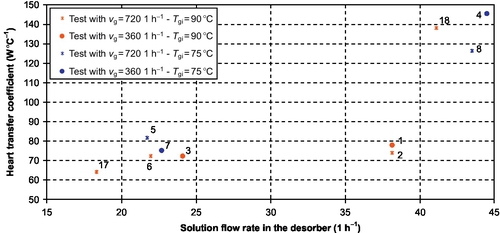
3.3.3.3.2 Heat Transfer in the Desorber
The observed power is acceptable, according to the process design for a real plant (2-5 kW; Table 3.4).
Average values of two indicators are evaluated and used for the heat transfer analysis: the overall heat transfer coefficient UA and the Reynolds number. For a test, ![]() (Equation (3.42)) is the average value of the calculated UA values at each measurement step during the test:
(Equation (3.42)) is the average value of the calculated UA values at each measurement step during the test:

Similarly, the average Reynolds number ![]() is defined as follows (Equation (3.43)):
is defined as follows (Equation (3.43)):
The solution properties are calculated at the desorber inlet.
The solution flow rate appears to be the variable that mostly affects the heat transfer rate in the explored experimental range (Figure 3.14): ![]() roughly doubles when the solution flow rate doubles. This significant change is not in accordance with the process simulation hypotheses, which assume that the solution side thermal resistance does not change significantly with the solution flow rate (N'Tsoukpoe et al., 2012). Anyway, the solution side remains the heat transfer controlling side.
roughly doubles when the solution flow rate doubles. This significant change is not in accordance with the process simulation hypotheses, which assume that the solution side thermal resistance does not change significantly with the solution flow rate (N'Tsoukpoe et al., 2012). Anyway, the solution side remains the heat transfer controlling side.
The plot of ![]() with respect to
with respect to ![]() allows further analysis: there is a significant change in the trend for
allows further analysis: there is a significant change in the trend for ![]() above 30-35 (Figure 3.15). The observed
above 30-35 (Figure 3.15). The observed ![]() range is from 10 to 40. According to studies on absorption falling film heat exchangers operating with LiBr aqueous solution, this yields two different flow regimes: the smooth laminar flow and the wavy laminar flow. Indeed, the smooth-wavy transition occurs between Re = 20 and 30 (Morioka and Kiyota, 1991; Kim et al., 1995; Medrano et al., 2002). The significant
range is from 10 to 40. According to studies on absorption falling film heat exchangers operating with LiBr aqueous solution, this yields two different flow regimes: the smooth laminar flow and the wavy laminar flow. Indeed, the smooth-wavy transition occurs between Re = 20 and 30 (Morioka and Kiyota, 1991; Kim et al., 1995; Medrano et al., 2002). The significant ![]() increase can then be explained by the change in the flow pattern. The low values observed during tests no. 1 and 2 (Figure 3.15) can be explained by the fact that they are quite in the transition zone.
increase can then be explained by the change in the flow pattern. The low values observed during tests no. 1 and 2 (Figure 3.15) can be explained by the fact that they are quite in the transition zone.
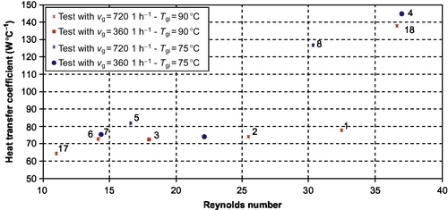
The occurrence of the wavy laminar regime, which is the most common in absorption falling film heat exchangers (Morioka and Kiyota, 1991) because it promotes the mixing of the film, has enhanced somewhat the heat transfer, but the design overall heat transfer coefficient (UA = 0.4 kW °C− 1, that is U = 1.2 kW m− 2 °C− 1) was not reached. The low heat transfer yields a large temperature difference between the solution and the HTF in the desorber (25-30 °C), when considering the corresponding power range (2-5 kW).
The main reason for this low performance is probably the maldistribution of the solution in the tubes due to the overflow weir distribution at the top of the tubes (see Section 3.3.3.1). A possible lack of verticality of the heat exchanger in the reactor could be another cause of poor distribution.
The maximum amount of heat that is charged during the different tests is 13 kWh. Thermal losses from the reactor are huge, as they can reach 25% of the total heat transferred. A better insulation of the reactor would reduce these losses.
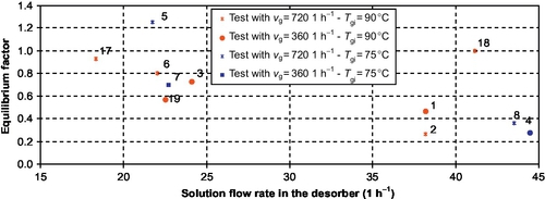
3.3.3.3.3 Equilibrium Factor
The observed equilibrium factor values range from 0.2 to 0.9. This equilibrium factor decreases with the solution flow rate increase (Figure 3.16). The film thickness increase, due to the solution flow rate increase, results in a slower water diffusion within the film to the interface, which is theoretically in equilibrium conditions. The waves induced by the Reynolds number increase have not improved the equilibrium factor.
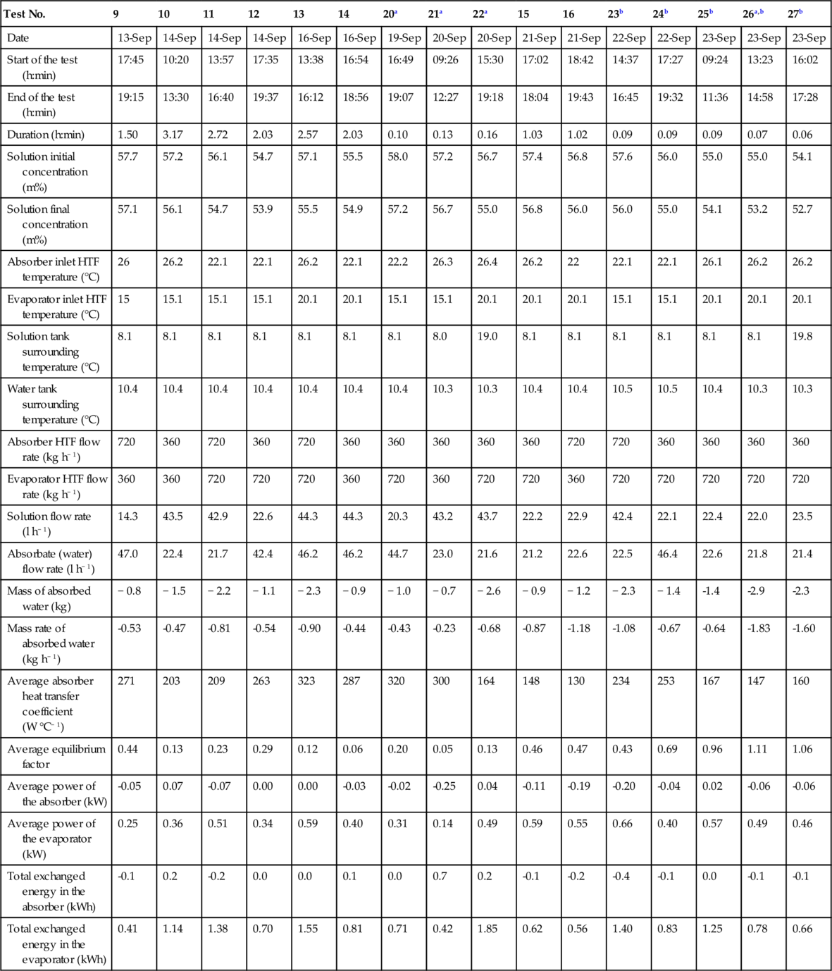
3.3.3.4 Experimental Results and Discussion in Discharging Mode
3.3.3.4.1 Base Tests
The observed results are summarized in Table 3.5.
Table 3.5
Discharging Test Results Summary (N'Tsoukpoe et al., 2013)
| Test No. | 9 | 10 | 11 | 12 | 13 | 14 | 20a | 21a | 22a | 15 | 16 | 23b | 24b | 25b | 26a,b | 27b |
| Date | 13-Sep | 14-Sep | 14-Sep | 14-Sep | 16-Sep | 16-Sep | 19-Sep | 20-Sep | 20-Sep | 21-Sep | 21-Sep | 22-Sep | 22-Sep | 23-Sep | 23-Sep | 23-Sep |
| Start of the test (h:min) | 17:45 | 10:20 | 13:57 | 17:35 | 13:38 | 16:54 | 16:49 | 09:26 | 15:30 | 17:02 | 18:42 | 14:37 | 17:27 | 09:24 | 13:23 | 16:02 |
| End of the test (h:min) | 19:15 | 13:30 | 16:40 | 19:37 | 16:12 | 18:56 | 19:07 | 12:27 | 19:18 | 18:04 | 19:43 | 16:45 | 19:32 | 11:36 | 14:58 | 17:28 |
| Duration (h:min) | 1.50 | 3.17 | 2.72 | 2.03 | 2.57 | 2.03 | 0.10 | 0.13 | 0.16 | 1.03 | 1.02 | 0.09 | 0.09 | 0.09 | 0.07 | 0.06 |
| Solution initial concentration (m%) | 57.7 | 57.2 | 56.1 | 54.7 | 57.1 | 55.5 | 58.0 | 57.2 | 56.7 | 57.4 | 56.8 | 57.6 | 56.0 | 55.0 | 55.0 | 54.1 |
| Solution final concentration (m%) | 57.1 | 56.1 | 54.7 | 53.9 | 55.5 | 54.9 | 57.2 | 56.7 | 55.0 | 56.8 | 56.0 | 56.0 | 55.0 | 54.1 | 53.2 | 52.7 |
| Absorber inlet HTF temperature (°C) | 26 | 26.2 | 22.1 | 22.1 | 26.2 | 22.1 | 22.2 | 26.3 | 26.4 | 26.2 | 22 | 22.1 | 22.1 | 26.1 | 26.2 | 26.2 |
| Evaporator inlet HTF temperature (°C) | 15 | 15.1 | 15.1 | 15.1 | 20.1 | 20.1 | 15.1 | 15.1 | 20.1 | 20.1 | 20.1 | 15.1 | 15.1 | 20.1 | 20.1 | 20.1 |
| Solution tank surrounding temperature (°C) | 8.1 | 8.1 | 8.1 | 8.1 | 8.1 | 8.1 | 8.1 | 8.0 | 19.0 | 8.1 | 8.1 | 8.1 | 8.1 | 8.1 | 8.1 | 19.8 |
| Water tank surrounding temperature (°C) | 10.4 | 10.4 | 10.4 | 10.4 | 10.4 | 10.4 | 10.4 | 10.3 | 10.3 | 10.4 | 10.4 | 10.5 | 10.5 | 10.4 | 10.3 | 10.3 |
| Absorber HTF flow rate (kg h− 1) | 720 | 360 | 720 | 360 | 720 | 360 | 360 | 360 | 360 | 360 | 720 | 720 | 360 | 360 | 360 | 360 |
| Evaporator HTF flow rate (kg h− 1) | 360 | 360 | 720 | 720 | 720 | 360 | 720 | 360 | 720 | 720 | 360 | 720 | 720 | 720 | 720 | 720 |
| Solution flow rate (l h− 1) | 14.3 | 43.5 | 42.9 | 22.6 | 44.3 | 44.3 | 20.3 | 43.2 | 43.7 | 22.2 | 22.9 | 42.4 | 22.1 | 22.4 | 22.0 | 23.5 |
| Absorbate (water) flow rate (l h− 1) | 47.0 | 22.4 | 21.7 | 42.4 | 46.2 | 46.2 | 44.7 | 23.0 | 21.6 | 21.2 | 22.6 | 22.5 | 46.4 | 22.6 | 21.8 | 21.4 |
| Mass of absorbed water (kg) | − 0.8 | − 1.5 | − 2.2 | − 1.1 | − 2.3 | − 0.9 | − 1.0 | − 0.7 | − 2.6 | − 0.9 | − 1.2 | − 2.3 | − 1.4 | -1.4 | -2.9 | -2.3 |
| Mass rate of absorbed water (kg h− 1) | -0.53 | -0.47 | -0.81 | -0.54 | -0.90 | -0.44 | -0.43 | -0.23 | -0.68 | -0.87 | -1.18 | -1.08 | -0.67 | -0.64 | -1.83 | -1.60 |
| Average absorber heat transfer coefficient (W °C− 1) | 271 | 203 | 209 | 263 | 323 | 287 | 320 | 300 | 164 | 148 | 130 | 234 | 253 | 167 | 147 | 160 |
| Average equilibrium factor | 0.44 | 0.13 | 0.23 | 0.29 | 0.12 | 0.06 | 0.20 | 0.05 | 0.13 | 0.46 | 0.47 | 0.43 | 0.69 | 0.96 | 1.11 | 1.06 |
| Average power of the absorber (kW) | -0.05 | 0.07 | -0.07 | 0.00 | 0.00 | -0.03 | -0.02 | -0.25 | 0.04 | -0.11 | -0.19 | -0.20 | -0.04 | 0.02 | -0.06 | -0.06 |
| Average power of the evaporator (kW) | 0.25 | 0.36 | 0.51 | 0.34 | 0.59 | 0.40 | 0.31 | 0.14 | 0.49 | 0.59 | 0.55 | 0.66 | 0.40 | 0.57 | 0.49 | 0.46 |
| Total exchanged energy in the absorber (kWh) | -0.1 | 0.2 | -0.2 | 0.0 | 0.0 | 0.1 | 0.0 | 0.7 | 0.2 | -0.1 | -0.2 | -0.4 | -0.1 | 0.0 | -0.1 | -0.1 |
| Total exchanged energy in the evaporator (kWh) | 0.41 | 1.14 | 1.38 | 0.70 | 1.55 | 0.81 | 0.71 | 0.42 | 1.85 | 0.62 | 0.56 | 1.40 | 0.83 | 1.25 | 0.78 | 0.66 |
a Absorber concurrent operating mode.
b Use of the 2-ethyl-1-hexanol.
The solution entering the absorber at 10-20 °C leaves it with a temperature of about 30-40 °C. Absorption occurs in the absorber and the produced temperature is sufficient for heating purposes (32-40 °C).
Generally, by disregarding the thermal loss to the ambient and assuming that there is no heat exchange between the solution and the HTF (balance of the overall heat exchange is zero), the absorption power is about 0.5 kW only (calculated with the solution flow temperature increase, that is, sensible heat).
3.3.3.4.2 Use of a Heat and Mass Transfer Enhancement Additive
It is an established fact that adding 2-ethyl-1-hexanol (2EH) in a LiBr aqueous solution improves its absorption heat and mass transfer characteristics (Ziegler and Grossman, 1996). Some tests were carried out after adding 2EH in the solution storage tank (100-200 ppm). The results show a slight improvement in the water absorption rate (≈+ 20%, see in Table 3.5: test no. 11 vs. test no. 23; test no. 12 vs. test no. 24). An increase in the equilibrium factor (Equation (3.9)) from 0.23 (tests without additive) up to 0.85 was also observed. However, no improvement in the overall heat transferred to the HTF was noticed.
3.3.3.4.3 Rise of the Absorber Inlet Solution Temperature
Two tests (no. 22 and no. 27) have been performed in order to know if the increase of the entering solution into the absorber had a major impact on the system performance. The temperature of the water bath around the solution tank was increased to 20 °C in order to feed the absorber with a higher temperature solution (basically, the storage tanks' surrounding temperature was maintained around 10 °C for the basic tests). This would be comparable, for instance, to the use of a SHX, as stated previously (see Figure 3.9), which would recover heat from the absorber outlet solution to increase the temperature of the absorber inlet solution. The corresponding tests have not yielded more satisfactory heat transfer to the HTF (power < 0.1 kW).
3.3.3.4.4 Possible Improvement Paths for the Absorber
Improving the performance of the absorber means improving its heat transfer coefficient.
The poor heat transfer coefficient seems mostly due to the hydraulic problems mentioned in Section 3.3.3.4.1. The size or the number of the orifices should be adjusted.
To address this issue, a SHX can also be used between the absorber and the solution tank for heat recovery (Figure 3.9). In absorption chiller and heat pump processes, this heat recovery unit is generally put between the absorber and the desorber in order to recover heat from the desorber outlet solution and preheat its inlet solution. This increases significantly the process thermal efficiency. The SHX would increase the absorber inlet solution temperature. Simulations (N'Tsoukpoe, 2012) show that the storage density is improved by about 30% when a SHX with an effectiveness ɛ = 0.8 is added to the process. The required solar collector area is also reduced significantly (50%). However, during desorption periods, there is a risk of crystallization in the SHX on the desorber outlet side. Indeed, the solution LiBr mass fraction is high and its temperature decreases in the SHX. To avoid such an eventuality, the SHX could be used only in discharging periods. The effect of this prevention measure on the storage density would be marginal, but the benefit of the required solar collector surface reduction would be lost.
Generally speaking, although the falling film type absorbers are the most commonly encountered absorber type in absorption machines (Kim et al., 1999), they feature several problems: low mass and heat transfer and large volume. An adiabatic absorber appears to be a solution to overcome these points and could be a better solution for this storage process. In an adiabatic absorber, an adiabatic part is introduced prior to the heat transfer part: the mass and heat transfer phenomena are separated (Grossman, 1982). The adiabatic and the heat exchange parts can be designed as two separate chambers in series or as one chamber. A specific constraint is the reversibility of the absorber unit so that it could be used in desorption mode, too.
3.4 Conclusion
In recent years, storage of thermal energy has become a very important topic in many engineering applications and has been the subject of a great deal of research activity. This chapter reviews the system and materials for thermal storage of solar energy. The chapter provides insight into recent developments on systems, materials, their classification, their limitations, and possible improvements for their use. Three major thermal energy storage modes (sensible, latent, thermochemical and sorption heat storage) are described, emphasizing the main characteristics of the most suitable heat storage materials for each.
Water remains the most widely used material in sensible heat storage systems used for solar energy storage. It is the material that presents the best compromise between cost, heat storage capacity, density, and environmental impact. Most of the technological projects are today focusing on the development of tools for the optimization of efficient energy consumption more than on the development of new systems with water for energy storage management.
Considering latent heat storage, numerous PCMs have been developed in the 0-80 °C temperature range, which is suitable for low-temperature solar heat needs. The advantages of latent heat storage materials on sensible heat storage materials are their high storage energy density and the various melting temperatures that allow different levels of use. The investigations on these materials are still underway and are attempting to overcome a number of their limitations (low thermal conductivities, supercooling, incongruent melting, etc.) and improve their viability.
Considering sorption/thermochemical heat storage, the technique theoretically offers the greatest heat storage capacity and does not suffer from heat losses during the storage period. But the literature on these processes is marginal compared to that on sensible and latent heat storage materials. The reason is that the research in this field is still in an early stage. There has been an intensification of the research during the last decade to develop more efficient sorption heat storage systems. New thermochemical materials have been characterized and innovative system designs have been developed and tested.
This chapter presents a focus on a long-term solar heat storage system based on water absorption by an LiBr aqueous solution. A detailed dynamic model of the system has been developed for the system simulation in order to evaluate the process performance and optimize its design. It shows the need to allow the crystallization of the solution in the solution tank, as this crystallization greatly enhances the storage capacity of the system. It also brings to light the need for efficient heat and mass exchangers both for the solution (for the absorber and the desorber) and the water (evaporator, mostly), as the exchangers' efficiency is directly linked to the process efficiency and heat storage capacity. A prototype of the system has also been presented in detail, as well as experimental results in the process charging and discharging modes. The prototype has been charged under practical conditions. Although the obtained heat transfer coefficients in the desorber are less than expected, mainly for hydraulic problems, the charging process has been proved with a charging power of 2-5 kW and heat storage up to 13 kWh. Crystallization has been achieved in the storage tank and the crystal dissolution/formation has been observed during several cycles. Discharging tests indicate absorption temperatures of about 30-40 °C, which may enable house heating. However, the absorption heat recovery by the HTF is not effective due to an inadequate design of the absorber. This proves that the design and optimization of the absorber and evaporator is a key research issue for the future of this process. Another research path should lead to innovative sorption couples less expensive than LiBr/H2O, as the amount of sorbent that would be used in a real building to cover its annual needs is too high to allow the use of this costly compound.
The thermal energy storage field is a complicated and multidisciplinary research domain. The scientific and technical barriers are not only concerned with heat and mass transfer, materials, component design and systems, but also with environmental impact, economical constraint, social acceptability, citizen sensibility, and so on. Ongoing research and development studies show that the challenges of the technology focus on the aspects of different types of storage technologies, process and system development, the innovative components, the configurations of storage cycles, and new and advanced materials. Booming progress illustrates that thermal storage is a realistic and sustainable option for storing solar energy, both for high temperature or low temperature, for short- or long-term applications. To bring the storage solutions into the market, more intensive studies in fields of evaluation of advanced materials and development of efficient and compact prototypes are still required.