
Solar Electrical Energy Storage
Yulong Ding1; Yongliang Li1; Chuanping Liu2; Ze Sun3 1 School of Chemical Engineering & Birmingham Centre of Energy Storage, University of Birmingham, Birmingham, UK
2 Department of Thermal Engineering, University of Science and Technology Beijing, Beijing, China
3 National Engineering Research Centre for Integrated Utilization of Salt Lake Resources, East China University of Science and Technology, Shanghai, China
Abstract
Solar power is expected to play an important role in the future electricity supply chain. However, many challenges remain to be overcome. One such challenge is the intermittent nature of the energy source. A potential solution to the challenge is the use of energy storage technologies. This chapter provides an overview of the area, covering technical requirements of solar electrical energy storage, options for the storage technologies, utility-scale and distributed-scale storage technologies, and economic aspects of the storage technologies.
2.1 Background
Modern societies become increasingly dependent on reliable and secure supplies of electricity to underpin economic growth and community prosperity. This makes electricity an important vector in current and future energy systems, with the latter particularly related to electrification of heat and transportation. In the United Kingdom, the current end user demand on electricity accounts for around 18%. Under the Carbon Plan scenarios, this share will increase to 25-31% by 2030 and 33-44% by 2050 (Taylor et al., 2013). Globally, the net electricity generation will increase by 93% in the IEO2013 reference case, from 20.2 trillion kWh in 2010 to 39.0 trillion kWh in 2040 (EIA, 2013). This implies that the world electricity generation will have to rise by 2.2% per year from 2010 to 2040, compared with an average growth of 1.4% per year for all delivered energy sources. Electricity will supply an increased share of the world's total energy demand, and hence become the world's fastest growing form of delivered energy.
Currently, electricity is produced mainly from fossil fuels. However, due to the long-term pernicious effects of greenhouse gas emissions on the environment, the decreased availability of fossil fuel resources, and the growing sense of urgency toward energy security, the use of more and more renewable and environmentally sustainable energy resources is inevitably happening and is expected to be dominant in the foreseeable future. Solar energy is regarded as a leading contender for green energy production. In fact, solar power installations are currently increasing by 40% per year worldwide (Ginley et al., 2008). According to the estimation of Energy Technology Perspectives 2014, solar power could be the dominant source of green energy by 2050 (IEA, 2014).
Solar energy can be converted to electrical energy in two main ways (Li et al., 2012). One is through solar cells (photovoltaic technology), which directly convert the short wave range of solar radiation energy into electrical energy. The other is via an indirect solar thermal route, which converts the solar radiation energy into thermal energy by means of solar collectors or concentrators, which then generates electricity through a conventional thermal cycle. However, sunlight is diffuse and intermittent. Weather conditions also determine the availability; power generation using both the technologies is unpredictable and unreliable. Therefore, substantial use of solar power to meet humanity's needs requires electrical energy storage to ensure a reliable power supply.
2.2 Technical Requirements of a Solar Electrical Energy Storage Facility
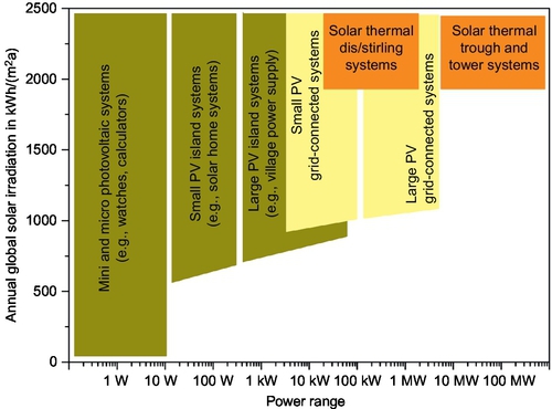
Currently, solar cells and solar thermal power systems cover a wide range of applications, from less than 1 W to 100s MW, as shown in Figure 2.1 (Quaschning and Muriel, 2001). It should be noted that solar thermal power plants can only use direct solar irradiance for power generation, while solar cells can convert both direct irradiance and diffuse irradiance. Therefore, solar cells can produce some electricity even with cloud-covered skies, making them applicable even with very low solar irradiation. Generally speaking, solar cells are most suitable for small-scale low-power demands, which are able to operate as standalone systems as well as grid-connected systems, whereas a solar thermal power plant is often a better option for large-scale and grid-connected systems. Due to different applications, there are different configurations to create a solar electricity installation with a solar cell facility, a solar thermal power plant, or both. However, from the role in the electricity supply chain, the installation can be classified into two categories: utility-scale solar electrical facility and distributed solar electrical facility.
Utility-scale solar power generation refers to medium- to large-scale solar energy installations, which can either be thermal power plants or solar cells. These units are designed to generate large amounts of electricity, which require large vacant lands and therefore are located in rural or semi-wild regions. As a result, they are far from end users and have to be physically connected to existing grids at discrete points. With increasing solar electricity penetration, utility-scale energy storage systems are required to provide utility-controlled functions, including long-duration electricity shift and capacity firming. Although there are no recognized standards at present, it is expected that the storage systems should have a maximum power rating of 1-20 MW (charging and discharging) and the ability to store 2-6 h of energy for on-demand delivery to the electric grid (EPRI, 2011). With such capacity, the storage system can provide a tremendous advantage to solar power generation efficiency and production, while lessening the negative effects of solar power generation on the grid. The energy storage systems are also expected to be used as a spinning reserve to delay committing additional fossil fuel power generation units. These imply that the following are required for energy storage systems for utility-scale solar power generation:
• Storage properties—high storage capacity, long charge/discharge times, good partial-load feature, and acceptable round-trip efficiency
• Financial performance—low capital cost, easy to maintain, and environment-friendly
• Other aspects—fast start-up and response for load following
On the other hand, distributed solar power generation refers to small- to medium-scale systems. Such systems are most commonly solar cell based, except for dish/Stirling solar thermal power systems. They are designed to generate moderate amounts of electricity, which require a small amount of land; hence, they can be placed in local electrical distribution systems at both the generation and use points. They could either be stand-alone systems, or they could be used to generate more electrical energy in conjunction with nearby installations. Compared to utility-scale systems, the generated electricity from distributed systems can only be used locally in most cases, rather than sold to electricity grids. As a result, a robust energy storage system that can charge/discharge more frequently is a necessity in order to offer inherently high service reliability to local electrical systems. The main characteristics required for energy storage technologies in distributed solar electricity systems include load response, round-trip efficiency, lifetime, and reliability.
2.3 Options for Solar Electrical Energy Storage Technologies
Except for thermal energy storage (TES) in concentrated solar power and solar fuels, electricity is generated by solar radiation first before charging into storage units. As a result, current available electrical energy storage technologies are potential options for solar electrical energy storage. These technologies can be categorized according to the following forms of stored energy (Chen et al., 2009):
• Electrical and magnetic forms: (i) Electrostatic energy storage (capacitors and supercapacitors); (ii) Magnetic/current energy storage (superconducting magnetic energy storage)
• Mechanical form: (i) Kinetic energy storage (flywheels); (ii) Potential energy storage (pumped-hydroelectric storage and compressed air energy storage (CAES))
• Chemical form: (i) Electrochemical energy storage (conventional batteries such as lead-acid, nickel metal hydride, lithium-ion, and flow batteries such as zinc bromine and vanadium redox); (ii) Chemical energy storage (hydrogen, solar fuel)
• Thermal form: (i) Cold and cryogenic energy storage (CES) (e.g., in solid and liquid materials); (ii) Heat storage (sensible heat storage using, for example, solid and liquid materials; latent heat storage using phase change materials); (iii) Thermochemical energy storage using heat of a reversible reaction or sorption process (thermochemical energy storage may also be regarded as energy stored in the chemical form); (iv) Combined TES (pumped thermal electricity storage (PTES))
The previous categorization is widely applied; however, more fundamentally, all energy storage technologies can be categorized into two forms of kinetic and/or potential energy at different spatial and time scales. Another method of classification is as follows, depending on the relationship between storage medium and charging/discharging devices:
• Coupled energy storage: If the charging/discharging devices are fully integrated with the storage medium, the technology is regarded as coupled. Examples of such storage technologies include rechargeable batteries, flywheels, capacitors, and so on. The advantage of coupled energy storage is the fast response rate and high efficiency, which allow the technology to manage short timescale fluctuations on the electrical supply chain.
• Decoupled energy storage: If the storage medium can be fully separated from the charging/discharging device, namely if the storage is in an independent container, the system is considered to be decoupled energy storage technology. Examples of decoupled energy storage technologies include pumped-hydro storage (PHS), CAES, flow batteries, TES, and hydrogen/fuel storage. In decoupled energy storage systems, the energy content is only limited by the storage vessel and is therefore potentially cheaper for long charging/discharging period applications.
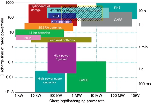
Coupled energy storage technologies deal with “power” applications, while decoupled energy storage technologies are suitable for “energy” applications. Figure 2.2 (Li, 2011; Li et al., 2011) shows a map of the application regime of most storage technologies. Decoupled storage technologies with a large energy storage capacity, such as PHS and CAES, TES, flow batteries, and solar fuels/hydrogen, can provide enough capacity to smooth diurnal fluctuations in solar power supply and are therefore suitable for utility-scale solar electrical storage. On the other hand, as both charging and discharging processes have energy loss, the round-trip efficiency of decoupled electrical energy storage technologies is lower. For small-scale distributed solar electrical facilities, rechargeable batteries are better options because they offer faster responses and higher round-trip efficiencies, although the capital cost is higher. Flywheels and supercapacitors can smooth very short-term fluctuations (at millisecond levels), such as those caused by line faults. However, they are very expensive for use in a solar electricity system for “energy” management, and therefore will not be discussed in this chapter.
2.4 Utility-Scale Storage Technologies
2.4.1 Pumped-Hydro Storage
PHS is the most widely used and technically matured bulk electrical energy storage technology. It currently accounts for approximately 98% of all global energy storage installations. PHS is based on the hydroelectric principle and hence does not have issues associated with SOx, NOx, greenhouse gases, and particulate matter emissions. PHS stores excessive electricity as the potential energy of raised water against gravity. Due to the use of efficient water wheels or hydraulic turbines to extract the kinetic energy of moving water and convert the energy into electricity through generators, it can provide ancillary services with better part-load efficiency, better controllability, lower maintenance costs, and minimal start-up costs (Succar and Williams, 2008). These advantages enable PHS (as well as hydroelectric generation) to play a central role in the operation of large-scale electricity grids, in particular when there is a large share of renewable electricity such as solar power. As a stabilizer for electricity grids, PHS systems could ensure that solar electricity supply is both regular and steady.
The major drawback of PHS technology lies in the fact that suitable and available sites for water reservoirs, essential for a PHS plant, are scarce, and in most cases are far from solar power plants. As a result, some new ideas have been developed in the past decade to address the issues. The following are two examples:
• Underground PHS uses underground caverns or water structures as lower reservoirs (Gonzalez et al., 2004). Conceptually, this seems a logical and sound solution for energy storage. However, the practical design and actual construction of large underground PHS systems are highly challenging. Consequently, this is still in the stage of feasibility study, and no project has ever been built (Crotogino et al., 2001; Schulte, 2001).
• Ocean PHS uses the high-elevation coastal region as the upper reservoir to retain ocean water, and the ocean itself as the lower reservoir. Challenges associated with this technology include reservoir sealing and corrosion of the pump turbine (DIT, 2004). Despite the challenges, there is already an ocean PHS in Okinawa, Japan. This plant, the first in the world, has been in operation for more than 10 years (EPRI, 2012).
Other recent developments in the area of PHS technology are the introduction of adjustable-speed motor/generators. Conventional PHS plants with a single-speed machine can only provide frequency regulation in the generation mode. With adjustable speed, it is possible to operate in pump mode as well in the range of 60-100% of rated capacity (Pimm and Garvey, 2009). This means an adjustable speed unit can change pumping power and provide load following and frequency regulation in both the generation mode and the pumping mode, making the technology more attractive in absorbing fluctuating solar power. Furthermore, with conventional single-speed machines, the pump turbines can only achieve their peak efficiency in one of the two modes, not both, whereas the adjustable technology can achieve both. Two Japanese companies, Toshiba and Hitachi, are leading the design and manufacture of high-power adjustable-speed motor/generators. In fact, eleven adjustable-speed pumped storage units have entered commercial service, with nine in Japan and two in Germany (Havel, 2011; Lima et al., 2004).
2.4.2 Compressed Air Energy Storage
CAES is a commercially available technology capable of providing very large energy storage capacity (above 100 MW in single units). Currently, CAES accounts for approximately 20% of global energy storage installations, except for pumped hydro. CAES is based on conventional gas turbine technology, with the compression and expansion processes decoupled. In a traditional gas turbine power station, around two-thirds of the turbine output is needed for compressing the combustion air (Ibrahim et al., 2008). In a CAES power station, however, no compression is needed during turbine operation because the required enthalpy is already included in the compressed air. As a result, the net power output for a given sized turbine expander can be 2.5 times that for the compressor load (Septimus, 2006).
Large CAES systems are designed as central storage facilities to cycle on a daily basis and to operate efficiently during partial-load conditions. This design approach allows CAES units to swing quickly from generation to compression modes, which can efficiently absorb or compensate solar power. CAES plants can also respond to load changes to provide load following, because they are designed to sustain frequent start-up/shut-down cycles.
The technical feasibility of CAES has been proven by two large-scale installations. These installations have been successfully running for decades, and as a result, CAES can be regarded as a mature technology. However, the fact that there have been no installations in recent years raises some concerns about the technology. (In fact, some planned large-scale CAES projects have been either terminated/canceled or postponed.) Technically, this may be associated with low round-trip efficiency and economics. The low round-trip efficiency is due to the following aspects:
• The air compression process is highly irreversible, particularly for high-pressure ratios.
• Storage of compressed air is commonly under constant volume conditions. This leads to a great loss of energy due to the throttling process of higher pressure charging and lower pressure discharging (Jovan et al., 2011).
• The expansion process is irreversible, though it is less serious compared to the compression process.
The combination of the previous points gives relatively low round-trip efficiency of around 40%. Even for the new planned facilities in the United States, the round-trip efficiency levels are expected to be between 42% and 54%, depending on the way the waste heat is used (Safaei et al., 2013).
To resolve the issues, recent developments of CAES technology have been in the storage vessel and energy conversion processes, which could ultimately contribute to round-trip efficiency improvement and cost reduction. These include constant-pressure storage vessel (e.g., water-compensated container (Kim et al., 2011), underwater container (Pimm and Garvey, 2009), adsorption-enhanced CAES) and novel energy conversion processes (e.g., near-isothermal CAES (Li, 2011; Li et al., 2011), advanced adiabatic CAES (Bullough et al., 2004)). However, most of these are still in their early research stage, and no reports have been seen on demonstrative scale systems.
2.4.3 Thermal Energy Storage
Thermal energy storage (TES) refers to technologies that store a thermal form of energy, which can be heat or cold. TES technologies can be broadly divided into two categories of thermophysical and thermochemical, with the principle of the former based on the temperature difference and/or latent heat due to phase change, and that of the latter on reaction or sorption enthalpy. Thermophysical-based TES is much more technically developed than thermochemical-based TES. Globally, TES technologies account for approximately 54% of global energy storage installations, except for pumped hydro. TES technologies can be used in both supply side and demand side management. In the demand side, TES is largely distributed and mostly at an individual building scale for domestic heating or cooling. For example, almost 14 million households in the United Kingdom have a hot water cylinder, giving a maximum combined storage capacity of around 80 GWh (Taylor et al., 2013). However, only recently has it been recognized that TES can also be an effective means of electricity management at the supply side.
Potential applications of TES technologies are ample. Examples include solar electrical energy management, particularly solar thermal power generation such as concentrating solar power (CSP), cryogenic energy storage (CES), Pumped Thermal Electricity Storage (PTES), and advanced adiabatic CAES (Bullough et al., 2004).
CSP is unique compared with solar photovoltaics and other renewable energy generation methods because it can be effectively integrated with TES. In addition, TES can decouple the thermal energy production process from the thermal energy utilization (power generation) process in CSP plants. This makes TES highly attractive due to fewer energy conversion steps and hence lower energy losses. At the heart of TES technologies is the storage medium (material). Currently, solar thermal power generation uses synthetic oil (e.g., VP1) and molten salt (e.g., solar salt) as the storage materials. Because these materials also act as heat transfer fluid, they are in the liquid form. As a result, they only store sensible heat with limited energy density. The use of phase change materials and the thermochemical method (with high energy density) is still in the development stage (Gil et al., 2010).
CES is a newly developed electrical energy storage technology that uses cryogen (e.g., liquid air/nitrogen) as the storage medium (Li, 2011; Li et al., 2011). The charging process is through air liquefaction, which consumes excessive electricity, whereas the discharging process is liquid air/nitrogen fuelled power generation. CES is potentially attractive for utility-scale electrical energy storage, as cryogen can be stored at low pressures (close to ambient) and has a much higher volumetric storage density (> 10 times that of CAES and > 100 times that of PHS) (Li et al., 2010). Additionally, cryogen is not only the energy carrier, but also the working fluid in the energy release process. Because cryogen has a relatively low critical point compared to steam, waste heat (e.g., from the exhaust of a new or existing simple-cycle gas turbine) can be recovered efficiently in the CES system (around four times more efficiently than in the Organic Rankine Cycle system) to achieve high energy-storage efficiencies (Strahan, 2013). However, without an external heat source, an independent CES system has relatively low efficiency (below ~60%) due to the high energy consumption of the air liquefaction process (Chen et al., 2009). Another potential issue is that current liquid nitrogen/oxygen production facilities are designed for continuous operation. This is in contradiction to the main function of the storage system to absorb excessive electricity. CES is a pre-commercial technology, with a 350 kW/2.5 MWh scale demonstration in operation since 2011 and a 5 MW/15 MWh demonstration plant to be completed in early 2015 in the United Kingdom (HPS, 2014). Current research and development efforts are mainly on round-trip efficiency improvement through process integration, novel liquefaction process for better flexibility, and system scale-up.
PTES is a recently proposed concept based on reversible heat pump cycles (Howes, 2012). In the charging process, the system works as a heat pump converting electricity into thermal energy (both heat and cold); in the discharging process, the system works as a heat engine to convert cold and heat into electricity. The greatest challenge of the PTES technology is associated with the mechanical components (compressor-expander coupled machinery), which need to have high efficiencies in both forward (charging process) and reverse (discharging process) operations (Desrues et al., 2010). In particular, a PTES system has to use an inert gas such as helium or argon instead of commonly used refrigerants to produce high-grade thermal energy (below − 150 °C at the cold end and above 600 °C at the hot end). The high-grade heat and cold are stored as “sensible heat” in insulated cylindrical vessels containing an appropriate thermal storage medium (e.g., a packed bed of pebbles or gravel, or a matrix of ceramic material). Heat exchange is through direct contact between the working fluid and storage medium, enabling a quick switch between charging/discharging modes and efficient integration with the thermodynamic cycle, and avoiding the “pinch-point” difficulties associated with phase-change storage methods. However, because a complete charging and discharging cycle involves twice as many compression, expansion, and heat transfer processes, the round-trip efficiency of PTES is limited due to the irreversibility of these processes. PTES technology is still in the early stage of development, and according to a UK company's plan, a 1.5 MW/6 MWh demonstrative storage unit will be deployed on a UK grid-connected primary substation in the near future (ETI, 2013).
2.4.4 Flow Battery
Modern redox flow batteries (RFBs) were invented in 1976 by Lawrence Thaller at the National Aeronautics and Space Administration (NASA) (Thaller, 1976). RFBs convert electrical energy into chemical potential energy by means of a reversible electrochemical reaction between two liquid electrolyte solutions contained in external electrolyte tanks. The conversion between electrical energy and chemical energy occurs as the liquid electrolytes from storage tanks flow through electrodes in a cell stack. In contrast to conventional batteries, they store energy in electrolyte solutions and the energy is proportional to the amount of electrolytes in the tanks (Ferreira et al., 2013). The cell has two compartments (positive half-cell and negative half-cell) separated by a membrane to prevent mixing of the electrolytes (Wang et al., 2013; Tan et al., 2013). Compared with other decoupled electrical energy storage technologies, RFBs have relatively high round-trip efficiencies, short response times, a symmetrical charge and discharge process, and quick cycle inversion.
RFB energy storage systems are being developed for use in small-scale applications, such as stand-alone power systems with solar photovoltaic arrays or wind turbines, and distributed energy installations for electric utility services. The first true RFB used a ferric/ferrous (Fe2 +/Fe3 +) halide solution electrolyte in the positive half-cell and a chromic/chromos (Cr2 +/Cr3 +) halide solution electrolyte in the negative half-cell. The battery soon encountered severe cross-contamination that resulted in dramatic capacity decay. The effort made to mitigate the cross-contamination led to the invention of the all-vanadium redox flow battery (VRB), which concerns only one active element in both positive and negative electrolytes, utilizing four different oxidation states of vanadium ions to form the redox couples. VRBs could have a round-trip efficiency of > 70% (Skyllas-Kazacos and Robins, 1988). They have an expected lifespan of 15 years with a low environmental impact (Rydh, 1999), and as a result, a considerable amount of fundamental and applied research has been carried out (Zhao et al., 2006).
In addition to VRBs, there has been work on other flow batteries (Chakrabarti et al., 2011; Liu et al., 2013; Yan et al., 2013; Ponce et al., 2006). Some of them have been studied for solar energy storage (Chakrabarti et al., 2011; Liu et al., 2013; Yan et al., 2013). Examples include ruthenium-based RFBs (Chakrabarti et al., 2011) and a combination of RFBs with dye-sensitized solar cells (Liu et al., 2013; Yan et al., 2013).
2.4.5 Solar Fuels
Solar fuels store solar energy in a chemical form for use when sunlight is not available. The most widely investigated solar fuels are hydrogen and hydrocarbon (Licht et al., 2001; Yamada et al., 2003). There are a number of methods for solar fuel production. For example, hydrogen production can be done by water electrolysis, thermolysis, and photolysis. These production methods are either indirect or direct. Indirect hydrogen production occurs through converting solar radiation into another form of energy, such as heat and electricity, followed by fuel production. Direct methods harness solar energy to produce fuels without any intermediary conversion steps. In principle, the indirect methods have the disadvantage of low efficiency due to losses in the intermediary conversion steps, but practically, they are easier to implement. Today, many advanced large-scale water electrolysis units are in operation with an electricity-to-hydrogen efficiency of over 75%, while most other solar hydrogen production processes are still at the stage of laboratory research (Licht et al., 2001; Yamada et al., 2003). Production of solar fuels is not the only challenge, particularly for solar hydrogen; challenges are also found in hydrogen storage and electricity regeneration steps. Although hydrogen can be stored as compressed gas, liquefied gas, or in a solid hydrogen carrier, none of these are currently energy-efficient or cost-effective. Fuel cells are currently regarded as a promising energy extraction technology for hydrogen. They are about four times more expensive than combustion engines/turbines, and two to three times shorter in terms of lifespan (Li et al., 2010). Significant efforts are therefore needed to address these issues.
Instead of hydrogen production, combining the water-splitting process with CO2 can generate liquid fuels (Rakowski and Dubois, 2009; Benson et al., 2009; Centi et al., 2007). These fuels have higher volumetric energy densities compared to hydrogen, and could potentially alleviate challenges associated with hydrogen storage. The liquid solar fuel routes have been shown to be achievable in research labs, but scaling up to commercial level faces a number of challenges, including system efficiency and lifetime and capital costs (Cook et al., 2010).
2.5 Distributed Scale Storage Technologies—Rechargeable Batteries
A rechargeable battery stores and releases energy through reversible chemical reactions (Ribeiro et al., 2001). Battery energy storage systems have been shown to play an important role in household demand smoothening (Purvins et al., 2013). Integrated renewable electrical energy systems often use rechargeable batteries, particularly in regions with distributed power systems and in remote areas. To meet the actual demands, rechargeable battery systems are sometimes integrated with weather forecasts and market signals, and are always colocated with renewable energy resources to improve system stability through frequency response and ramp control and to improve the economics of the renewable generator through leveling the output of solar generators (Hill et al., 2012). Several types of batteries could be used for distributed solar electrical energy system, and they are described in the following subsections. As will be seen, the main difference between these batteries lies in the electrodes and electrolytes, which also determine their specific characteristics.
2.5.1 Lead-Acid Battery
The lead-acid battery, invented in 1859 by Gaston Plante, is the oldest and most widely used rechargeable electrochemical device in automobile, uninterrupted power supply (UPS), and backup systems for telecom and many other applications. Such a device operates through chemical reactions involving lead dioxide (cathode electrode), lead (anode electrode), and sulfuric acid (electrolyte) (Parker and Garche, 2004). Lead-acid batteries have a high round-trip efficiency, and are cheap and easy to install. It is the affordability and availability that make this type of battery dominant in the renewable energy sector. It is also well known that lead-acid batteries have low energy density and short cycle life, and are toxic due to the use of sulfuric acid and are potentially environmentally hazardous. These disadvantages imply some limitations to this type of battery. Indeed, a recent study on economic and environmental impact suggests that lead-acid batteries are unsuitable for domestic grid-connected photovoltaic systems (McKenna et al., 2013).
2.5.2 Lithium-Ion Battery (Li-Ion)
The first lithium battery was built in 1979 (Mizushima et al., 1980). Lithium batteries in the early days suffered from poor cycle life and safety problems. It was the development of lithium-cobalt batteries with carbon as negative electrodes that led to the successful commercialization of lithium-ion batteries by Sony in 1990. The term “lithium batteries” actually means a family of dozens of different battery technologies based on moving lithium ions between a positive electrode consisting of a lithium and transition metal compound and a negative electrode material. Due to the nature of the reactions involved and the structure of electrodes, lithium-ion batteries have a much longer cycle life than lead acid batteries do (McDowall, 2008). Lithium-based batteries have high round-trip efficiency, high energy and power density, and a low self-discharge rate, and have been widely used in portable electronics. High power density also makes lithium-ion batteries an option for powering electrical vehicles. Efforts have also been made to extend the application range to solar energy storage applications (Guo et al., 2012).
2.5.3 Nickel-Based Battery
Nickel-based batteries mainly refer to nickel-cadmium (Ni-Cd), nickel-metal hydride (Ni-MH), and nickel-zinc (Ni-Zn) batteries. Ni-Cd batteries consist of a positive electrode with nickel oxyhydroxide as active material, and a metallic cadmium-based negative electrode with aqueous potassium hydroxide as electrolyte (Shukla et al., 2001). The advantages of such batteries include robustness to deep discharges, long cycle life, temperature tolerance, and high energy density (compared with lead-acid batteries). However, the cadmium used in Ni-Cd batteries is highly toxic. This leads to the development of Ni-MH batteries, which are much more environmentally friendly, though they have a high self-discharge rate. Despite various developments, only Ni-Cd batteries have found commercial application in UPS systems. Recently, Ni-Cd batteries became one of the popular storage technologies for solar energy generation because they can withstand high temperatures, though the high initial investment of Ni-Cd battery systems may hinder widespread application in the sector (Nair and Garimella, 2010).
2.5.4 Sodium-Sulfur Battery
The development of sodium-sulfur (NaS) battery technology has been ongoing for more than 50 years. NGK of Japan was the first to commercialize the technology successfully. NaS batteries consist of liquid (molten) sulfur at the positive electrode and liquid (molten) sodium at the negative electrode as active material, separated by a solid beta alumina ceramic electrolyte (Hadjipaschalis et al., 2009). They have high energy density, long cycle life, and high round-trip energy efficiency. These features make the technology suitable for load leveling, power quality, and peak shaving in distributed energy systems, including solar power (Baker, 2008). In fact, current global installations of NaS batteries exceed 300 MW, despite recent concerns about the safety aspects.
2.5.5 Other Battery Technologies
Intensive research efforts have been made in recent years, seeking new storage technologies that can economically provide the power, cycle life, and energy efficiency needed to respond to the short-term transients arising from renewables and other aspects of grid operation. The following are some examples of recent developments.
A new type of aqueous electrolyte battery has been proposed and demonstrated (Pasta et al., 2012). Such a technology relies on the insertion of potassium ions into a copper hexacyanoferrate cathode and a novel activated carbon/polypyrrole hybrid anode. The cathode reacts rapidly, with very little hysteresis. The hybrid anode uses an electrochemically active additive to tune its potential. It has been demonstrated that a 95% round-trip energy efficiency can be achieved when cycled at a 5C rate, and the efficiency reduces to 79% when cycled at 50C. The results also show a zero-capacity loss after 1000 deep-discharge cycles.
An aqueous rechargeable sodium-ion battery has recently been proposed. This technology uses NaCuHCF as cathode, NaTi2(PO4)3 as anode, and aqueous Na2SO4 solution as electrolyte. Lab experiments have shown a voltage of 1.4 V and a specific energy of 48 Wh/kg based on the total weight of the active electrode materials (Wu et al., 2014). In addition, the aqueous Na-ion battery has also shown an excellent high-rate discharge capability and cycle capability, with 88% capacity retention over 1000 cycles at a 10C rate.
A novel symmetric open-framework electrode battery is proposed and demonstrated experimentally (Pasta et al., 2014). The battery is shown to provide a maximum specific energy of 27 Wh/kg at a 1C rate based on the mass of the active material (Pasta et al., 2014). At a 50C rate, the battery has a specific energy of 15 Wh/kg, a specific power of 693 W/kg, and an energy efficiency of 84.2%. These performance data suggest that this type of battery is suitable for grid-related applications, including smoothing of intermittent variations in power production associated with the integration of renewable energy.
2.6 Economics of Solar Electrical Energy Storage Technologies
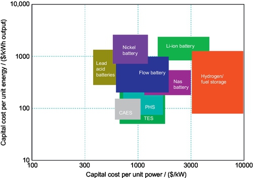
Apart from technical performance, capital and operating costs also determine whether an electrical energy storage technology is viable for solar power generation. The principal components for comparing different electrical energy storage technologies are the costs per unit charged/discharged power that storage can deliver ($/kW), and costs per unit energy capacity ($/kWh) stored in the storage system. Although it is difficult to evaluate a specific technology because the costs are influenced by a wide range of factors, including system size, location, local labor rate, market variability, environmental considerations, and transport/access issues, Figure 2.3 (Chen et al., 2009; IME, 2014) shows a comparison that provides a high-level understanding of the issues. From the view of capital cost, the lead-acid battery is the best option for distributed-scale solar power storage, while TES is preferred for utility-scale solar power storage.
In practical applications, however, the lifetime cost has to be considered. This is affected mainly by two additional factors: round-trip efficiency and cycle life. Cycle life refers to the number of charge and discharge cycles that a storage device can provide before performance decreases to an extent that it cannot perform the required functions. This is extremely critical for distributed-scale applications. Figure 2.4 shows the round-trip efficiency and cycle life of different energy storage technologies (Chen et al., 2009; IME, 2014). One can see that the lifetime of lead-acid batteries is much shorter than that of other technologies.

From Figures 2.3 and 2.4, one can also find that hydrogen/fuel storage is very expensive and of low round-trip efficiency. This makes it an unfavorable option for stationary applications. However, it should be noted that hydrogen/fuel is the only dispatchable option that is a potential replacement for transportation fuels.
2.7 Final Remarks
Solar electrical energy storage is an emerging area that is still under extensive research and development. Many challenges remain to be overcome. Solar electrical power is rarely used as the only energy resource in an energy system or a grid. In most cases, solar power is integrated with other renewable energy sources or fossil-fuel-based power generation to provide a reliable electricity supply to end users. As a result, the electrical energy storage units are used to provide services to the integrated system/grid instead of a solo solar power facility (with the exception of TES in a CSP plant). The selection of specific storage technology must therefore be considered at a system/grid level, including not only the characteristics of solar power generation, but also features of other energy resources as well as the characteristics of transmission and end users.