Solar Thermal Energy Storage for Solar Cookers
Ashmore Mawire Department of Physics and Electronics, Northwest University, Mmabatho, South Africa
Abstract
An overview of the three main types of solar cookers is presented in this chapter, and the basic operating principles of direct-focusing, oven, and indirect solar cookers are outlined. These three types of cookers are reviewed and discussed when they are used in conjunction with solar thermal energy storage (TES) units to enhance their usefulness during periods when solar radiation is not available. Solar cookers using both sensible-heat thermal energy storage and latent-heat thermal energy storage are reviewed and discussed. Advantages and disadvantages of the different types of solar cookers with TES are also highlighted. Methods of characterizing solar cookers are presented, and it is concluded that more research efforts are needed to develop methods of characterizing solar cookers with TES systems. The most viable options for solar cookers with TES for developing countries are oven solar cookers and direct-focusing solar cookers, because they are relatively cheap to fabricate and maintain. On the other hand, when issues of efficiency and safety are concerned, indirect solar cookers with TES are more viable; these can be implemented for community-scale cooking because they are relatively expensive to construct. Solar cookers with TES offer an alternative to polluting fossils and liquid petroleum gas in rural areas of developing countries.
14.1 Introduction
Solar thermal energy storage (TES) for solar cookers allows for cooking of food during periods when the sun is not available, thus enhancing their usefulness. The viable options of storing thermal energy for solar cookers are sensible-heat thermal energy storage (SHTES) and latent-heat thermal energy storage (LHTES).
In SHTES, heat is stored by heating a material (or extracted by cooling) without any change in its phase. The specific heat capacity of the material and the temperature change during the heating cycle determine the amount of heat that can be stored in a given volume. A variety of materials can be used for such systems, including water, heat-transfer oils, inorganic molten salts, pebbles, and rocks. With solids, the material is often in the porous form, and heat is stored or extracted by the flow of a fluid through the solid pores or the bed voids.
LHTES is based on the heat absorbed or released when a storage material undergoes a phase change. A solid phase change material (PCM) is A material with a high heat of fusion and it is capable of storing large amounts of energy when melting at a certain temperature. This energy is then released when the material solidifies. Because heat is absorbed or released when the material changes phase, PCMs are classified as LHTES units. PCMs can be classified as organic, inorganic, and eutectic. Organic PCMs include fatty acids and paraffins, while inorganic PCMs are usually hydrated salts. A eutectic PCM is a melting composition of two or more components.
In this chapter, a brief general overview of the main types of solar cookers is presented. Basic operating principles of the solar cookers are discussed. Solar cookers with TES are reviewed and discussed to cater to the intermittent behavior of the solar energy resource. Solar cookers using both SHTES and LHTES are presented. Methods of characterization of solar cookers with TES systems are also presented.
14.2 Solar Cooking Systems
A solar cooker is a device that uses energy from the sun to cook (Mawire, 2009). Solar cookers have been in existence for more than a century, with one of the first reported in India by Adams (1878). Essentially, three types of solar cookers exist, and these are classified according to their different designs. The three types of solar cookers are direct-focusing solar cookers, oven solar cookers, and indirect solar cookers.
14.2.1 Direct-Focusing Solar Cookers
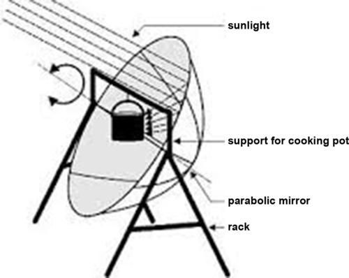
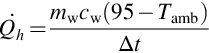
Direct-focusing solar cookers, also referred to as concentrating solar cookers, use reflectors to focus and concentrate sunlight directly onto a usually smaller and darker cooking pot compared to the reflector. The pot is either suspended or set on a stand at the focal region. These cookers consist of one or more reflectors and a framework that supports both the reflectors and the pot. Numerous arrangements of these cookers have been devised to allow the reflector to be tilted to always point toward the sun, with the pot remaining at the focal region. The types of reflectors used for these cookers include parabolic dish reflectors, spherical reflectors, plane mirror reflectors, and parabolic trough reflectors. A direct-focusing parabolic dish solar cooker is shown in Figure 14.1.
A direct-focusing solar cooker operates by concentrating reflected solar radiation from a larger aperture area onto an absorbing device referred to as a receiver. The receiver absorbs energy and is able to cook food contained in it. The ratio of the larger reflecting aperture area to the smaller absorber area is the geometric concentration ratio given as (Rabl, 1985):
where Aap is the aperture area and Aabs is the absorber area. The total rate of solar radiation (or power) incident onto the absorber from the reflector aperture is given as:
where Pi is the incident power, ηo is the optical efficiency, I is the solar radiation power flux measured in W/m2, and Aap is the aperture area. Equation (14.2) is rather idealistic because no heat losses have been considered, and it is assumed that the reflector aperture receives all the incident solar radiation and concentrates it all onto the absorber.
If a known amount of water mw is placed in a pot at the focal region of the solar cooker, the energy absorbed by the water for a time interval Δt or (the output energy) is given as:
where cw is the specific heat capacity of water, and Twf and Twi are the final and initial water temperatures in the time interval. The instantaneous energy efficiency is thus the ratio of the output energy to the incident absorbed solar radiation, and is expressed as:

Direct-focusing cookers are reasonably priced and cheap to construct and achieve high temperatures in a short interval of time. However, these cookers have a number of disadvantages, some of which may be alleviated by the use of a TES system. Some of the disadvantages are (a) the reflective surface material degrades, (b) the cooking pot is exposed to many hazards, (c) they are less versatile, (d) some designs with long focal points may hurt the eyes, and (e) they perform poorly during cloudy or hazy periods because they utilize direct solar radiation.
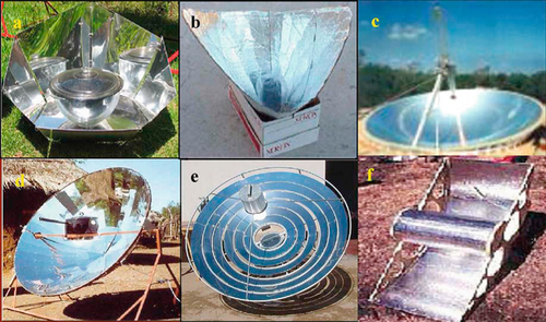
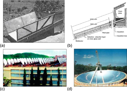
Most reflectors for the solar cookers focus the solar radiation from below the receiver, whereas only a few focus the radiation from above the receiver. Spherical reflectors, parabolic reflectors, and Fresnel reflectors are examples of reflectors that focus solar radiation from below the receiver. Different types of direct-focusing solar cookers described by Muthusivagami et al. (2010) are shown in Figure 14.2.
14.2.2 Oven Solar Cookers
Oven solar cookers are basically insulated boxes with glazed covers that cook food using the greenhouse effect. Variations of these types of solar cookers exist, and these cookers are also referred to as solar box cookers (SBCs). Solar radiation that enters the oven cooker through a glazed window (plastic or glass) gets absorbed inside and heats the darker inside walls and the cooking vessels. Because heat cannot escape through the glazed window, the oven gets hot. Booster mirrors around the window can also be used to direct more solar radiation into the oven. A principal advantage of oven solar cookers over direct-focusing cookers is that they can use both the direct and the diffuse components of solar radiation. A further advantage of these cookers is that no solar tracking is required to focus the solar radiation. Operating temperatures of about 200 °C can be achieved with these solar cookers when booster mirrors are utilized. These temperatures are adequate for cooking most types of food, except for prolonged frying. Heat transfer into and within an SBC occurs by conduction, convection, and radiation.
For a very simple SBC with no reflectors, the energy entering the glazed collecting window is
where Aap is area of the glazed collecting window, τg is the transmissivity of the glazing material, and Ip is the global solar radiation that is incident normal to the collecting window. In reality, the apparent area of the window will change with the angle of the sun’s rays. This variation is given by
where Aapp is the apparent area, Aper is the perpendicular area, θ is the solar azimuth, and φ represents the difference between the solar elevation angle and the collecting window tilt angle. The azimuth angle is the coplanar angle between a line pointing due south (in the northern hemisphere) and a line pointing toward the sun as seen from a stationary point. The solar elevation angle is the angle of the sun’s position relative to a plane tangent to the earth at a point on which the observer is standing (Shaw, 2004). The tilt angle is the angle between the collecting window’s normal and a plane tangent to the earth upon which the collecting window is sitting (Shaw, 2004).
The useful energy efficiency of an SBC is defined as the ratio of the energy output to the energy input, and can be expressed as (El-Sebaii and Ibrahim, 2005):
where Mf and Cf are the mass and the specific heat capacity of the cooking fluid inside a pot, respectively. ΔTf is the change in the cooking fluid temperature, Δt is the time required to achieve the maximum temperature of the cooking fluid, and Iav is the average solar intensity during the time interval Δt with a reference value equal to 900 W/m2.
Different designs of oven solar cookers as presented by Muthusivagami et al. (2010) are shown in Figure 14.3 according to the number of reflectors. Although oven solar cookers do possess some advantages over direct-focusing cookers, their main disadvantages are that they have low efficiencies, they require more time to cook food, they have limited capacity dependent on the size of the cooker, they have limited varieties, and they cannot be used for indoor cooking.
14.2.3 Indirect Solar Cookers
Indirect solar cookers are solar cookers constructed such that the solar energy collectors are separated from the cooking vessels. A heat transfer medium is usually required to bring the collected energy into the cooking vessel. The cooking vessel can be placed farther away from the solar energy collector, allowing for an indirect cooking mode (Mawire, 2009). Solar energy collectors can be placed on the roof, while the cooking vessel can be placed indoors. In theory, the distance between the solar energy collector and the cooking vessel can be very large. However, practical challenges such as heat loss and the circulation of the heat transfer medium limit this distance. Close proximity between the cooking vessel and the solar energy collector allows for heat transfer through natural convection. Indirect solar cookers have the advantages of indoor cooking, stability, ease of use, controlled cooking, and easy incorporation into a TES unit.
A heat transfer fluid (HTF) circulates around the solar energy collector to capture the solar radiation for cooking, and the rate of energy absorption by the circulating fluid is given by
where ṁf is the mass flow rate, cf is the specific heat capacity, Tfout is the outlet fluid temperature, and Tfin is the inlet fluid temperature. The solar collection instantaneous efficiency is defined as the ratio of the rate of heat transfer to the absorbed power, and is expressed as:
where AC is the solar collector area. The thermal sensible efficiency (da Silva et al., 2002) is the ratio of the energy used to heat a certain mass of water in the cooking vessel from the ambient temperature to 95 °C to the absorbed solar energy in a time interval dt. This is expressed as:
where mw is the mass of the water in the cooking vessel, cw is the specific heat capacity of the water, and Tamb is the ambient temperature. The denominator represents the absorbed solar energy, which is equivalent to the integral of the absorbed power for a time interval dt. The end temperature of 95 °C is used to avoid the uncertainty in the start of boiling.
The thermal sensible power is the rate of energy used to heat the water in the cooking vessel, and it is given as:
where Δt is the time interval. To estimate the boiling power, the numerator of Equation (14.11) can be replaced by the corresponding latent heat energy expression mwhfg to become

where hfg is the latent heat of vaporization of water. The average latent heat energy efficiency is determined as the ratio of latent heat energy to the absorbed solar energy, and is expressed as:

Indirect solar cookers of different designs are shown in Figure 14.4, as presented by Muthusivagami et al. (2010). A major disadvantage of indirect solar cookers is that they are rather expensive to build and maintain. Another disadvantage is that some of the solar cookers, especially those using solar concentrators, require constant tracking.
14.3 Solar Cookers Using Sensible Heat Thermal Energy Storage (SHTES)*
In this section, different types of solar cookers that have been designed using SHTES are discussed according to the three main types of solar cookers.
14.3.1 Direct-Focusing Solar Cookers Using HCTES
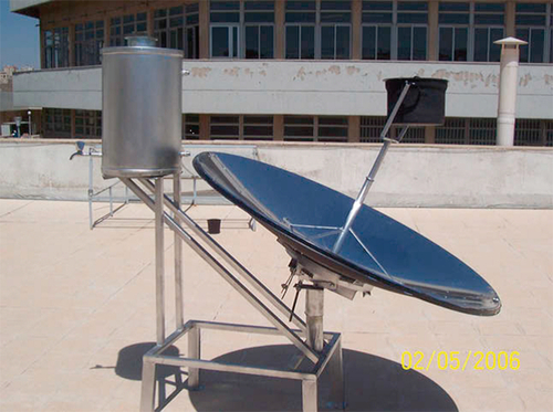
Direct-focusing solar cookers using sensible heat storage are rather rare, and only a few designs using SHTES have been proposed that operate principally in the indirect mode. A portable solar cooker and water heater using a parabolic concentrator, shown in Figure 14.5, was designed by Badran et al. (2010). The device was able to cook food and heat water in the storage tank. An umbrella type of parabolic dish concentrator that uses oil TES material was designed by Chandra et al. (2013) to heat the oil that was in thermal contact with the cooking surface. At night, water is poured through a funnel that leads into the oil storage vessel. The water in the pipes gets heated because of the hot oil inside the storage container. The water turns into vapor and comes out through pores that are used to cook rice.
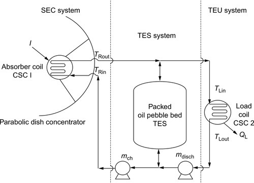
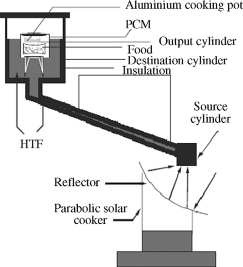
Mawire et al. (2008) proposed a solar cooker using a parabolic dish concentrator that could operate both in the direct and the indirect modes with an oil/pebble bed TES system. Models for the solar energy capture (SEC) system and the TES system were developed to simulate the performance of the TES system using two charging methods. The first method charged the TES system at constant flow rate, while the second method charged the TES system at constant temperature by varying the flow rate. Simulation results showed a greater degree of thermal stratification and energy stored in the TES system for constant temperature charging compared to constant flow-rate charging. Maximum energy efficiencies using both methods were comparable; however, the constant temperature method produced a greater exergy efficiency under high solar radiation conditions. The conceptual diagram of the solar cooker with an oil/pebble bed TES system is shown in Figure 14.6.
The simulation investigation done by Mawire et al. (2009) used an experimentally validated one-dimensional model for SHTES material in the solar cooker of Figure 14.6. The study compared three SHTES materials: fused silica, alumina, and stainless steel. The thermal performance of these materials was evaluated in terms of axial temperature distribution, total energy stored, total exergy stored, and transient charging efficiency. The results indicated that not only was the value of the total amount of energy stored important for the thermal performance of oil/pebble bed TES systems, but also the amount of exergy stored and the degree of thermal stratification should be considered. A high ratio of the total exergy to total energy stored was suggested as a good measure of the thermal performance of the pebble material. From the simulations, it was concluded that fused silica possesses the best thermal stratification performance, while stainless steel achieved the highest total energy stored at the expense of a greater drop in energy from the peak value as charging progressed. Alumina, on the other hand, was found to have the fastest energy storage rate and had the best exergy-to-energy ratio variation during the charging process, which was comparable to that of fused silica at the end of the charging process.
Discharging simulations of an oil/pebble bed TES system were done by Mawire et al. (2010). Two methods of discharging were compared, which were constant flow-rate discharging and controlled power discharging at a fixed load inlet temperature to maintain a fixed discharging power by varying the discharging flow rate. Results of discharging the TES system at a constant flow rate indicated a higher rate of heat utilization, which was not beneficial to the cooking process, because the maximum cooking temperature was not maintained for the duration of the discharging period. On the other hand, the controlled load power discharging method had a slower initial rate of heat utilization, but the maximum cooking temperature was maintained for most of the discharging process, which was desirable for the cooking process.
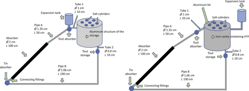
An experimental comparison of different storage materials for a small parabolic trough solar cooker was done recently by Mussard and Nydal (2013a). Although the storage tanks stored PCM during the phase change period, the storage tanks also stored sensible heat before the phase change process. Oil- and aluminum-based storage tanks were compared experimentally. The loop connecting the collector and the storage was filled with the heat transfer oil, which circulated by self-circulation. The first storage was mainly made of aluminum and salts, while the second was based on oil and salts. Figure 14.7 shows the two experimental configurations that were deemed to be operating in direct mode because the distance between the collector and the storage tank was small. Results showed that the oil-based system reached higher temperatures than the aluminum-based system, and the efficiency of the oil-based system was more than that of the aluminum-based system.
The charging of an oil-based heat storage tank coupled with a low-cost, small-scale, solar parabolic trough for cooking purposes was done by Mussard and Nydal (2013b). Two tests were carried out: one with an uninsulated absorber and the other with an insulated absorber. The results showed that at low temperatures, the absorber without insulation was much more effective. When the storage temperature approached 200 °C, the insulated tube became more effective. An SK-14 direct-focusing solar cooker without heat storage was experimentally compared with a solar parabolic trough solar cooker using a storage unit (Mussard et al., 2013). The SK-14 performed better than the solar cooker with storage due to the nonoptimized design of the cooking surface, which could be improved to match that of an electrical cooker.
14.3.2 Oven Solar Cookers Using SHTES
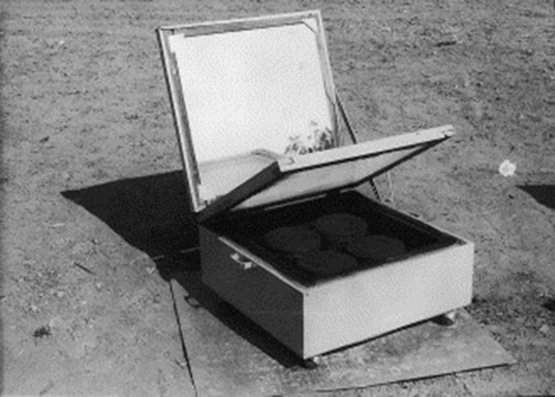
Designs of oven solar cookers or SBCs using sensible heat storage are also limited, and a few designs will be presented in this section. A hot-box solar cooker that uses engine oil as a storage material was designed, fabricated, and tested so that cooking can be performed at late evening times (Nahar, 2003). A photograph of the hot-box storage solar cooker is shown in Figure 14.8 (Muthusivagami et al., 2010). The device is a double-walled solar hot box. The outer box is made of a galvanized steel sheet, and the inner box is made of a double-walled aluminum sheet tray. The space between the inner trays is filled with 5.0 kg of used engine oil, and it is completely sealed. The space between the outer tray and the outer box is filled with glass wool insulation and separated by a wooden frame. The inner tray is painted black with blackboard paint. Nahar (2003) found out that the maximum stagnation temperature achieved inside the cooking chambers of the hot-box solar cooker with storage material was the same as that of the hot-box solar cooker without storage during the daytime, but it was 23 °C more in the storage solar cooker from 17:00 to 24:00 hours. The efficiency of the hot-box storage solar cooker was found to be 27.5%. Cooking trials were also conducted with rice and green vegetables using the hot-box storage cooker and with a hot-box solar cooker without storage from 17:30 hours. The food inside the hot-box storage cooker was cooked perfectly by 20:00 hours, while the food inside the hot box cooker without storage was not cooked at all.
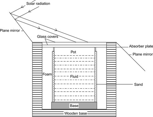
Ramadan et al. (1988) developed a hot-box solar cooker using sand as the storage medium, as shown in Figure 14.9. It consisted mainly of a wooden box with one opening. A copper absorbing flat plate painted black with two glass covers (3 mm thick and 25 mm apart) was placed on top of the box. A copper cylinder cooking pot was used. The pot cover was welded to the absorbing plate to obtain maximum possible thermal conduction. Four square reflecting plane mirrors were attached to the sides of the box to concentrate the solar insolation according to the angle of incidence. Six hours/day of cooking time were recorded, and approximately 3 h/day of indoor cooking were achieved due to the storage material. An overall efficiency of 28.4% was reported by the authors.
The experimental thermal performance evaluation of a box-type solar cooker using stone pebbles as TES material was done in Nepal (Shrestha and Byanjankar, 2007). For comparison purposes, a cooker without stone pebbles was tested with a solar cooker with stone pebbles. The experimental results of both no-load testing and load testing showed that with stone pebbles inside the cooker, the time for cooking food could be delayed by a considerable amount of time of about 2 h after noon, thus making cooker suitable for evening meals due to the stored heat. Alozie et al. (2010) compared the performance of three solar hot boxes: (a) a solar hot-box cooker without collectors, (b) a solar hot-box cooker with collectors, and (c) a solar hot-box cooker with heat storage stone pebbles. Results indicated that the storage type of cooker could keep temperatures high enough at around 90 °C by 18:00 hours for the possibility of evening cooking.
Oven solar cookers with SHTES have the disadvantages of achieving low temperatures due to low efficiencies, slow cooking speeds, and limited capacity depending on the size of the cooker.
14.3.3 Indirect Solar Cookers Using SHTES
The most popular designs of solar cookers with SHTES are indirect solar cookers; substantial research has been done on these kinds of cookers. Flat-plate indirect solar cookers, evacuated tube indirect solar cookers, and concentrating indirect solar cookers using SHTES have been designed, and a few of these designs are presented in this section.
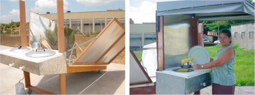
A flat-plate collector natural convection solar cooker with short-term coconut oil TES, shown in Figure 14.10, was designed by Haraksingh et al. (1996). A double-glazed flat-plate collector covered with a selective surface was used as the power source for the solar cooker. Coconut oil was used as the HTF, and at the highest part of the thermosiphon loop there was an oil bath in which two cooking pots were immersed to facilitate good heat transfer between the working fluid and the cooking pots. Temperatures of approximately 150 °C could be achieved between 10:00 and 14:00 hours under high solar radiation conditions. A flat-plate collector indirect solar cooker using a vegetable oil as the HTF and an oil/pebble bed TES system, which also uses the thermosiphon principle, is shown in the photograph of Figure 14.11 (Schwarzer and da Silva, 2003). The oil is heated up in the collector with reflectors and moves by a natural flow to the cooking unit. Manually controlled valves guide the oil flow rate either to the pots or to the storage tank. This type of solar cooker can be incorporated into a kitchen. The major advantages of this solar cooker are the possibility of indoor cooking, the use of a thermal storage tank to keep the food warm for longer periods of time for night cooking, and the high temperatures of the working fluid reached in a short period of time, allowing fast cooking as well as frying and roasting.

Solar cookers based on conventional flat-plate solar collectors suffer from the drawback of the performance deteriorating due to the reversed cycle during night and cloudy periods of the day. Further disadvantages are that they are expensive to construct, and the nonremovable pots make cleaning and dishing of food difficult.
Evacuated tube solar collectors (ETSCs) have a number of advantages over other types of solar collectors. These advantages include the following: the need for solar tracking is removed because they operate with direct as well as diffuse solar radiation, high temperatures can be achieved, cooking can take place in the shade or inside a building because of the spatial separation of collecting part and oven unit, their thermal conductance is extremely high, and the heat transfer between the evaporator and the condenser section is nearly isothermal.
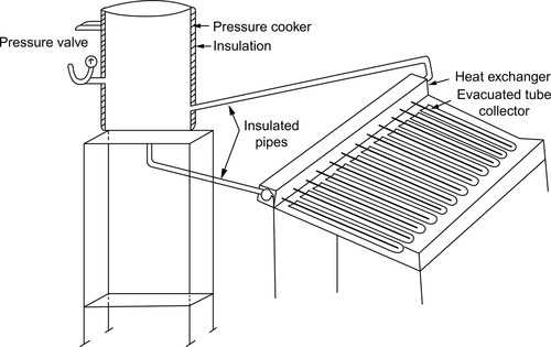
Kumar et al. (2001) designed the community-type solar pressure cooker based on an ETSC, as shown in Figure 14.12. It consists of an evacuated tubular solar collector and a pressure cooker that acts both as a cooking unit and a TES unit. Both units are coupled together by a heat exchanger. The incident solar irradiance falls onto the collector and heats up the working fluid inside the tubes. The vaporized fluid rises upward to the heat exchanger and transfers energy by condensation to the water flowing in the secondary loop of the heat exchanger. The condensed fluid then returns to the collector tubes, and the process of heat transfer continues. Batch-type cooking was suggested by the experimental results. In Australia, Morrison et al. (1993) developed an indoor type of solar cooker using evacuated heat pipes with a pressurized water heat storage tank, with an appeal similar to a normal electrical hot-plate cooker. The cooker used a sophisticated system whereby steam generated in an evacuated tubular absorber was transferred via a long pipe system into a storage vessel connected to the cooking plates.
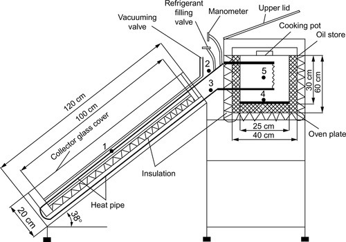
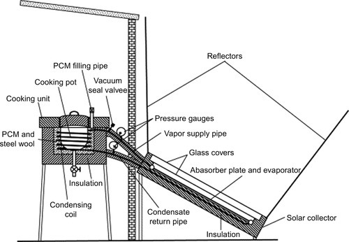
Balzar et al. (1996) developed a solar cooking system consisting of a vacuum-tube collector with integrated long heat pipes directly leading to the oven plate. The cooker was tested during several clear days. Detailed temperature distributions and their time dependences were measured. The maximum temperature obtained in a pot containing 51 L of edible oil was 252 °C. The design developed by Esen (2004) of an ETSC using different heat transfer refrigerants in the heat pipes with an oil TES system is shown in Figure 14.13 The oil reservoir of a capacity of 9 L was used for heat storage, allowing the cooker to be preheated and the foods to be kept warm after cooking. The maximum temperature obtained in a pot containing 7 L of edible oil was 175 °C. The cooker was successfully used to cook several foods, and cooking processes were performed with the cooker in 27-70 min periods.
Evacuated tube indirect solar cookers with TES are rather complex and expensive to fabricate. Added to this disadvantage, the tubes tend to deteriorate with time, thus reducing their overall performance.
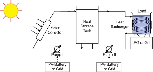
Concentrating solar collectors can achieve higher temperatures than the other types of solar collectors; hence, it is possible to perform high-temperature cooking applications like baking and frying. Two designs of indirect solar cookers that can also be used in the direct mode using parabolic concentrators have been discussed previously (Mawire et al., 2008; Mussard and Nydal, 2013a). A hybrid indirect solar cooker with an oil TES system and a parabolic dish concentrator was designed by Prasanna and Umanand (2011). A schematic diagram showing the hybrid solar cooking system is shown in Figure 14.14. The energy source is a combination of solar thermal energy and liquefied petroleum gas (LPG). Solar thermal energy is transferred to the kitchen by means of a circulating fluid. The transfer of solar heat is a twofold process, whereby the energy from the collector is transferred first to an intermediate oil storage tank, and this energy is subsequently transferred from the storage tank to the cooking load. During periods when the sun is not available, stored heat, LPG, or electricity can be used to cook foods such that cooking can be carried out at any time during the day.
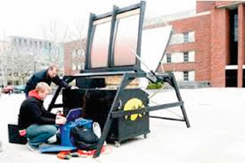
An innovative design of a Hawkeye solar cooker has been made by students at the University of Iowa and the University of California, Berkeley (Hawkeye solar cooker, 2011), using sand as a SHTES unit. A compound parabolic reflector was used to concentrate the solar radiation onto an absorbing box. The cooker was able to cook food and store heat. A photograph of the innovative Hawkeye solar cooker is shown in Figure 14.15.
Instead of using a HTF in indirect concentrating solar cookers, a secondary reflector can be used to focus the solar radiation onto a cooking device or onto a cooking device with a TES unit, as shown in Figure 14.16. Nyahoro et al. (1997) performed charging and discharging simulations using cast iron and granite charging blocks, and the results showed that cast iron had more energy stored and less energy lost during a charging and discharging sequence. The results also indicated that the height of the storage block should be at least one-fifth of the diameter of the block after different heights and diameters were simulated.

14.4 Solar Cookers Using LHTES
LHTES based on PCMs has the advantages of a higher energy storage density and an isothermal behavior during phase change, compared to SHTES material. This means that there is a significant decrease in the storage volume when using LHTES material, as compared to SHTES material. In the sections that follow, solar cookers using LHTES are discussed and reviewed.
14.4.1 Direct-Focusing Solar Cookers Using LHTES
Direct-focusing solar cookers using LHTES are an emerging technology; there are only very recent research studies done on these types of solar cookers. An experimental investigation of a solar cooker based on a parabolic dish collector with a PCM storage unit for Indian climatic conditions was performed by Chaudhary et al. (2013). Figure 14.17 shows a schematic diagram and a photograph of the receiver of the solar cooker. The solar cooker with the PCM TES unit was kept on the absorber plate of a parabolic dish concentrator. During the daytime, acetanilide PCM stored heat, and during the evening, the solar cooker was kept in an insulator box and the PCM delivered heat to the food. To enhance the performance of the solar cooker, three cases were considered: an ordinary solar cooker, a solar cooker with the outer surface painted black, and a solar cooker with the outer surface painted black along with glazing. Results indicated that the solar cooker with the outer surface painted black along with glazing performed better compared to the other two cases.
A portable solar cooker of a standard concentrating parabolic type that incorporated a daily PCM TES unit was evaluated by Lecuona et al. (2013a,b). The storage unit was made by using two conventional coaxial cylindrical cooking pots: an internal one and a larger external one. The space between the two coaxial pots was filled with PCM, forming an intermediate jacket. Figure 14.18 shows photographs of the solar cooker in operation, with the sun focused on the cooking pot, and the inner pot view with water. A model was developed to evaluate the thermal performance of the cooker, which was validated with experimental results. Two types of PCMs were evaluated: technical-grade paraffin and erythritol. Results indicated that cooking lunch for a family was possible with the simultaneous storage of heat during the day. Keeping the utensil afterward inside an insulating box indoors allowed for cooking dinner with the retained heat, and also allowed for using the heat for breakfast the next day.

Other types of direct-focusing solar cookers using PCM storage have also been reported (Foong et al., 2011; Arunasalam et al., 2012; Abinaya and Rajakumar, 2013). Direct-focusing solar cookers with PCM storage have the disadvantages of the PCM being relatively expensive compared to SHTES, thermal degradation of the PCM after numerous charging and discharging cycles, poor heat transfer due to the low thermal conductivity of the PCM, and the need of a solar tracking mechanism.
14.4.2 Oven Solar Cookers Using LHTES
When compared to direct-focusing solar cookers, oven solar cookers using LHTES have been in existence for a longer time and research work done on them is well documented. Some types of oven solar cookers using PCM storage will be presented in this section. The different types of oven solar cookers using PCM TES, as presented by Muthusivagami et al. (2010), are shown in Figure 14.19.
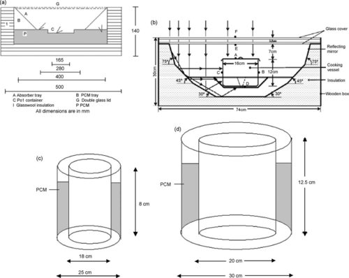
Buddhi and Sahoo (1997) designed and tested the solar cooker shown in Figure 14.19a with LHTES for cooking food late in the evening. In their design, the PCM was filled below the absorbing plate. Commercial-grade stearic acid was used as the PCM. In this design, the rate of heat transfer from the PCM to the cooking pot during the discharging mode of the PCM was slow, and more time was required for cooking food in the evening. Figure 14.19b shows the design by Domanski et al. (1995) of a solar hot-box cooker with LHTES. The possibility of cooking during nonsunshine hours using PCMs as storage media was investigated. Two concentric cylindrical vessels made from aluminum were connected together at their tops, using four screws to form a double-walled vessel with a gap between the outer and inner walls. The gap between the outer and the inner vessels was filled with 1.1 kg of stearic acid (melting temperature 69.8 °C) or 2 kg of magnesium nitrate hexahydrate (melting temperature 89.8 °C), which left sufficient space for expansion of the PCMs during melting. The cooker performance was evaluated in terms of charging and discharging times of the PCMs under different conditions. Results indicated that the performance depended on the solar irradiance, mass of the cooking medium, and the thermophysical properties of the PCM. The overall efficiency of the cooker during discharging of the PCM was found to be three to four times greater than that for steam and heat-pipe solar cookers, which can be used for indoor cooking.
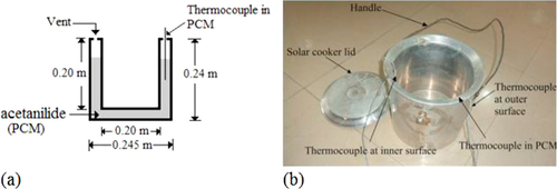
Sharma et al. (2000) designed and developed a cylindrical PCM storage unit for a box-type solar cooker to cook food late in the evening, as shown in Figure 14.19c. The PCM surrounded the cooking vessel, hence the rate of heat transfer between the PCM and the food was high. The designed PCM container had two hollow concentric aluminum cylinders, and the space between the cylinders was filled with acetamide (melting point 82.8 °C, latent heat of fusion 263 kJ/kg) as the PCM. To enhance the rate of heat transfer between the PCM and the inner wall of the PCM container, eight fins were welded at the inner wall of the PCM container. Results obtained from the experimental tests showed that by using 2 kg of acetamide as the PCM, a second batch of food could be cooked if it was loaded before 3:30 p.m. during the winter season. The researchers also recommended that the melting temperature of the PCM be between 105 and 110 °C for evening cooking, and thus there was a need to identify a storage material with an appropriate melting point and quantity that could be used to cook food late in the evening. Buddhi et al. (2003) developed a latent heat storage unit, shown in Figure 14.19d, for a box type of solar cooker with three reflectors. They used acetanilide (melting point 118.9 °C, latent heat of fusion 222 kJ/kg) as a PCM for night cooking. From the experimental results, the authors concluded that cooking experiments were successfully conducted for evening time cooking up to 20:00 hours, with 4.0 kg of PCM used in the storage unit.
Yuksel et al. (2012) experimentally investigated the potential use and effectiveness of paraffin wax in a solar hot-box cooker during daylight and late evening hours. A paraffin wax was used as the PCM, and metal shavings were used in conjunction with the PCM to enhance heat transfer. The effect of the reflector angle on the thermal efficiency of the cooker was tested with different solar insolation conditions on different days. It was concluded that the designed cooker could be used effectively at an angle of 30 °. The maximum temperature of the paraffin achieved during the experiments was in the range of 75.1-80.5 °C. The rectangular solar cooker filled with the paraffin wax was found to have a high thermal performance, which was indicated by high temperatures and decreased cooking times for the given design conditions.
The major drawbacks of oven solar cookers with PCM storage units are low heat transfer rates and low operating temperatures; thus, different heat transfer enhancement mechanisms have to be employed to improve their efficiencies.
14.4.4 Indirect Solar Cookers Using LHTES
Indirect solar cookers utilizing LHTES are a relatively new technology with a limited literature base, compared to oven cookers with LHTES. A few examples of different designs will be presented in this section.
Hussein et al. (2008) developed a novel indirect solar cooker, shown in Figure 14.20, with outdoor elliptical cross-section wickless heat pipes coupled to a flat-plate solar collector with an integrated indoor PCM TES and cooking unit. Two plane reflectors were used to enhance the solar radiation incident onto the collector, while magnesium nitrate hexahydrate (melting temperature 89 °C and latent heat of fusion 134 kJ/kg) was used as the PCM inside the indoor cooking unit of the cooker. Different experiments were performed with the solar cooker without loading and with different loads at different loading times to study the benefit of the elliptical cross-section wickless heat pipes and PCM in the indirect solar cooker. The PCM was evaluated in terms of cooking food at noon, cooking food in the evening, and keeping food warm at night and early in the morning. The experimental results indicated that the solar cooker could be used to successfully cook different kinds of meals at noon, afternoon, and evening times. The cooker could also be used for heating or keeping meals hot at night and early in the morning.
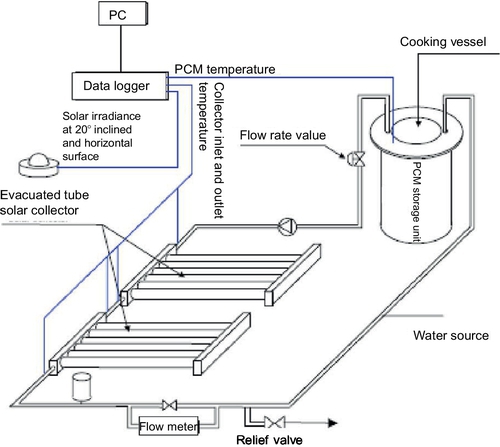
An indirect solar cooker based on an ETSC with a PCM storage unit was developed by Sharma et al. (2005). A schematic diagram of the indirect solar cooker is shown in Figure 14.21. The cooker consists of an ETSC, a closed loop pumping line-containing water as the HTF, a PCM storage unit, a cooking unit, a pump, a relief valve, a flow meter, and a stainless steel tubular heat exchanger. The PCM storage unit has two hollow concentric aluminum cylinders, and the space between the cylinders is filled with 45 kg erythrithol (melting point 118 °C, latent heat of fusion 339.8 kJ/kg). A pump circulates the heated water (HTF) from the ETSC through the insulated pipes to the PCM storage unit by using a stainless steel tubular heat exchanger that is wrapped around the cooking unit. During sunshine hours, heated water transfers its heat to the PCM and stores it in the form of latent heat through the stainless steel tubular heat exchanger. The stored heat is utilized to cook food in the evening or when sun intensity is not sufficient to cook food. Results of the experimental tests concluded that evening and noontime cooking were possible. Evening time cooking was also found to be faster than noontime cooking. Experimental results also indicated that this solar cooker yielded satisfactory performance despite the low heat transfer. A modified design of the heat exchanger in the TES unit was suggested to enhance the rate of heat transfer in that solar cooker.
Besides using flat-plate collectors or ETSCs, concentrating collectors may be employed with an LHTES unit for indirect solar cooking applications. One such design has been discussed previously (Mussard and Nydal, 2013a,b). Murty et al. (2007) designed and developed an inclined heat exchanger unit for an SK-14 parabolic solar concentrator (PSC) for off-place cooking, shown in Figure 14.22. The principal objective of this study was to use an inclined HTF column as heat exchanger unit and to evaluate the thermal performance of a PSC assisted with an inclined cylindrical heat exchanger unit for off-place cooking with and without PCM. Experiments were conducted for cooking foods on a normal day, with commercial-grade sodium acetate (melting point is 104 °C and latent heat of fusion is 230 kJ/kg) and acetanilide (melting point is 115.42 °C and latent heat of fusion is 189.4 kJ/kg) as the LHTES materials. The cooking experiments were conducted with the PCMs as TES media during charging and discharging of the PCMs. It was observed that the cooking time was less during discharging of the PCMs.
Complex-type indirect solar cookers using PCM storage for the future have also been proposed (Parida et al., 2013; Kenesarin and Mahkamov, 2007). Indirect solar cookers using PCM have the major drawbacks of poor heat transfer, complexity in design, and the expense in construction.
14.5 Characterization of Solar Cookers with TES
There are no general methods for characterizing solar cookers with TES, because different designs exist and general thermal performance measures only give rough comparative estimates. Most general methods or standards reported in the literature are applicable to the solar cooking device. This section presents existing solar cooking performance standards, and also presents new proposed figures of merit applicable to solar cookers with TES.
14.5.1 Existing Solar Cooking Standards
The thermal performance of solar cooking systems is determined with useful energy evaluations, and there are currently three well-developed testing standards (Shaw, 2004).
The first standard is the American Society of Agricultural Engineers (ASAE) standard, ASAE S580, which was developed by Funk (2000). This standard is simple and produces a useful and meaningful measure of solar cooker performance based on an energy evaluation. ASAE S580 monitors the average temperature inside a pot of water during operation of the cooker under guidelines given in the standard for tracking and thermal loading. Temperature measurements of the water are taken and averaged every 10 min. The ambient temperature as well as the normal irradiance (solar energy flux per area) are also measured and recorded. The tests are not conducted during windy conditions, low direct solar radiation conditions, and low ambient temperature. The primary figure of merit used by ASAE S580 is the cooking power, P, calculated as:
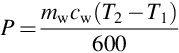
where cw is 4.186 kJ/kg/ K, T2 is the final temperature, and T1 is the initial temperature. 600 is the number of seconds in the 10-min interval. P is normalized to 700 W/m2 to yield.
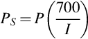
where PS is the standardized cooking power and I is the interval average solar radiation. PS is plotted against ΔT and a linear regression is performed. For standard reporting procedures, a temperature difference of 50 °C is used (i.e., Twater − Tambient = 50 °C), and the corresponding value of PS is reported as the “Cooking Power.” The performance evaluation only examines thermal performance, without looking at qualitative issues such as heat losses, safety, ease of use, and affordability.
The second testing standard is referred to as the Indian standard (Mullick et al., 1987). This standard is more technical than ASAE S580, and it provides two figures of merit. These figures are calculated to be as independent of environmental conditions as possible. The first figure of merit is
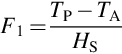
where Tp is the stagnation temperature of the absorber plate, TA is the ambient air temperature, HS is the solar radiation on a horizontal surface (taken at a time of stagnation), and the second is
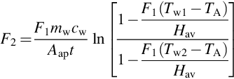
where Hav is the average horizontal solar radiation, Tw1 is the initial water temperature, and Tw2 is the final water temperature. By setting a reference temperature and solving Equation (14.17) for t, a characteristic curve can be developed that describes how long the cooker will take to reach the reference temperature. This method, however, does not take into account qualitative factors like cost and safety.
The third standard was proposed by the European Committee of Solar Cooking Research (ECSCR) and covers a wider scope than the other two standards (ECSCR, 1995). The ECSCR standard devotes more attention to safety factors and uses an exhaustive testing methodology. The evaluation process is driven by several detailed data sheets, which are filled out by the tester. The benefit of this procedure is that there is no need to measure normal incidence solar radiation, which usually requires a tracking pyrheliometer. The disadvantages of this method are errors encountered due to the rigorous testing method, the fact that the method is not suitable for multiple tests, and that it takes a long time (3 days) to complete a basic test.
To cater to the drawbacks of these three standards, a fourth and new standard for the testing of solar cookers that has flexible environmental testing conditions and also addresses qualitative factors like safety was proposed by Shaw (2004). Four thermal performance figures of merit were proposed: standard stagnation temperature, standard cooking power, standard sensible heating time, and unattended cooking time. The author also proposed that the tests be carried out between 10:00 and 17:00 hours, that the cooking vessels be filled with 5 kg of water per square meter of aperture area, that the cooker be tracked according to the manufacturer’s specifications, that tests be conducted with pots from the manufacturer, and that an electronic data logger be used. For the tests to be valid, it was also proposed that the wind speed be less than 2.5 m/s for a 10-min data-logging interval, that the ambient temperature be 20-35 °C during the tests, that the solar radiation be 500-1000 W/m2 for the 10-min interval, and that any presence of precipitation would make the affected results invalid. Though this standard is thorough, it has not been widely adopted by researchers because it is a recent standard.
Besides the generalized standards usually used for direct-focusing cookers and SBCs, methods of characterizing solar cookers, including the indirect types of cookers, have been proposed by Schwarzer and da Silva (2008). The cookers were classified into four types: Type A, flat-plate collector with direct use; Type B, flat-plate collector with indirect use; Type C, parabolic cooker with direct use; and Type D, parabolic cooker with indirect use. The characterization methods suggested that the cooking pots be filled with 5 kg of water or oil per 1 m2 of collector surface, and that the average solar radiation be higher than 800 W/m2. The authors also suggested that water be stirred to avoid stratification. For temperatures above 100 °C, oil was to be used with the caution of observing the self-ignition temperature of the oil. They proposed that four thermal performance parameters be evaluated, similar to those of Shaw (2004).
Another recent unified method of characterizing and comparing solar cookers of different geometries based on exergy was proposed and implemented by Kumar et al. (2012). Four exergy-based thermal performance parameters were proposed for solar cookers of different topological design. The four thermal performance parameters were peak exergy, quality factor, exergy temperature difference gap product, and heat loss coefficient. The exergy output power and temperature difference were plotted, and they resembled a parabolic curve for each design. The peak exergy (vertex of the parabola) was deemed acceptable as a measure of the device’s fuel ratings. The ratio of the peak exergy power gained to the exergy power lost at that instant of time was considered the quality factor of the solar cooker. The exergy power was found to vary linearly with temperature difference, irrespective of the topology of the device and the slope of the straight line obtained through curve fitting, representing the heat loss coefficient of the cooker.
14.5.2 New Solar Cooking Figures of Merit for Solar Cookers with TES
The thermal performance standards described in the previous section only consider the cooking device, and shed no insight into the storage capability of a solar cooker with TES. New thermal performance figures of merit to cater to a direct-focusing type of solar cooker and a box type of solar cooker with PCM TES were proposed by Lecuona et al. (2013a,b). The nominal heat stored in a cooking utensil can be expressed as
where Ms is the mass of the PCM, L is the latent heat of fusion, and cs is the specific heat capacity of the PCM, considered to the same for the solid and the liquid phases. The temperature range is defined for T0 > Tm > 70 °C, where Tm is the melting temperature for the PCM and 70 °C is the minimum temperature for sterilization. Mpcp is the heat capacity of the pot and Mwcw is the heat capacity of the walls. This heat is available for increasing the temperature of the food above the ambient conditions and for keeping the temperature against losses either (i) with no solar input (in the shade) or (ii) under the sun, depending whether it is cooking lunch, breakfast, or dinner. The time for cooking is very dependent on the nature of the food, so that establishing a standard time for keeping the temperature above heat losses is difficult.
A figure of merit can be evaluated considering the theoretical heat storage capacity compared with heat desired for cooking the nominal liquid mass load Ml,nom whose specific heat capacity is cl. Choosing the worst case scenario described previously (i), and equating Qs to the heat required to increase the temperature of the nominal water load Ml,nom to an equilibrium temperature Teq, leads to the limiting temperature that is expressed as:
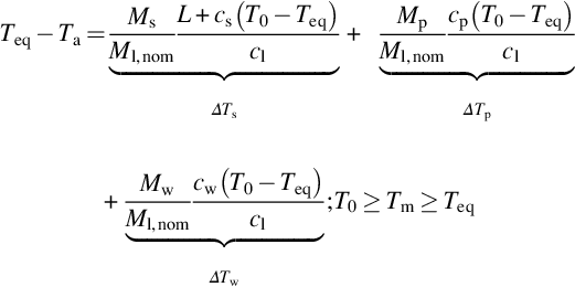
where the first term represents ΔTs, the second term ΔTp, and the last term ΔTw. In heat storing solar cookers, generally ∆Tp, ∆Tw ![]() ∆Ts, owing to the high melting heat L, Mp ~ Ms and generally cp, cw < cs.
∆Ts, owing to the high melting heat L, Mp ~ Ms and generally cp, cw < cs.
As with the stagnation test, if the resulting temperature is higher than 100 °C, oil must be selected for the liquid. ΔTs in Equation (14.19) varies between ≈ 50 °C for paraffins up to ≈ 110 °C for erythritol, so that with no losses, boiling is possible with a unity ratio of PCM mass to water mass, using the reported values. Another parameter also evaluated by Lecuona et al. (2013a,b) using detailed modeling for solar cookers with PCM TES storage is the useful heat power.
The figures of merit presented by Lecuona et al. (2013a,b) require detailed modeling, and these parameters are not valid for solar cookers with SHTES systems. Mawire et al. (2009) presented a very simple parameter, referred to as the exergy factor, which evaluates the ratio of the exergy stored to the energy stored during charging and discharging of a TES system, and is useful for both LHTES and SHTES systems. The exergy factor is simply a measure of the quality of energy obtained from a given quantity of energy. A high exergy factor indicates that high quality energy is available in a given quantity of energy. The exergy factor can also be used to evaluate the thermal energy performance of TES systems for indirect cookers.
14.6 Conclusion
An overview of the three main types of solar cookers has been presented, and the basic operating principles of direct-focusing, oven, and indirect solar cookers have been outlined. These three types of cookers have been also reviewed and discussed when they are used in conjunction with solar TES units to enhance their usefulness during periods when solar radiation is not available. Solar cookers using both SHTES and LHTES have been reviewed and discussed. Advantages and disadvantages of the different types of solar cookers with TES have also been highlighted. Methods of characterizing solar cookers have been presented, and it was concluded that more research efforts must be carried out to develop methods of characterizing solar cookers with TES systems.
The most viable options for solar cookers with TES for developing countries are oven solar cookers and direct-focusing solar cookers, because they are relatively cheap to fabricate and maintain. On the other hand, when issues of efficiency and safety are concerned, indirect solar cookers with TES are more viable; these can be implemented for community-scale cooking because they are relatively expensive to construct. Solar cookers with TES offer an alternative to polluting fossils and LPG in rural areas of developing countries.