
Revitalization of Hydro Energy
A New Approach for Storing Solar Energy
Z. Glasnovic; K. Margeta University of Zagreb, Zagreb, Croatia
Abstract
Currently, the most suitable technology for storing relatively large amounts of solar energy is hydro energy (pumped storage hydroelectricity (PSH)). Given the problem of intermittent solar energy and the inability to ensure a continuous energy supply to customers throughout the year, this chapter analyzes the integration of solar (photovoltaic or solar thermal) and hydro energy. With all known technologies of storage, only hydro energy can balance seasonal surpluses and shortages of solar energy, and in this way ensure continuous energy supply to consumers throughout the year with low environmental impact. The disadvantages of the site-specific construction of this system can be avoided by using geosynthetics for the construction of reservoirs of PSH in virtually all places where there are height differences. A very important polymer material, geomembranes, which belong to the group of geosynthetics (e.g., geotextiles, geogrids, geonets, geosynthetic clay liners, geopipe, geofoam, geocomposites), can significantly contribute to the further development of PSH technology. The results from the case study show that this concept of using hydro energy for solar energy storage could be flexible in design, construction, and operation.
8.1 Introduction
Energy storage is crucial for increasing the share of energy from renewable energy source (RES) generators. This especially applies to energy from the sun and wind, which is characterized by intermittence.
However, the problem with the present energy storage technologies is that they can be stored for a relatively small amount of energy, and in that sense a relatively short period of time to balance intermittent energy from RES generators (i.e., hourly, daily up to a maximum weekly value).
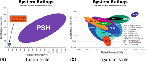
Figure 8.1 shows energy storage system ratings (Margeta and Glasnovic, 2011), while logarithmic scale (b) is converted in linear scale (a) gives insight into the possibilities of storing energy by the different technologies. Pumped storage hydroelectricity (PSH) technology is the solely technology that can significantly increase the share of RES generators in electric power systems (EPS). But precisely because of these qualities (i.e., storing the largest amount of energy), it is possible to balance summer surpluses and winter shortages of solar energy (SE). Thus, the essential characteristic of PSH technology is its storage of large quantities of energy, which allows balancing on an annual basis when weather conditions repeat. In that sense, this technology is suitable for a significant increase in the participation of RES generators in EPS.
When it is revealed that this technology is very acceptable in economic terms (average price of 0.5 $/W; see Deane et al., 2010), the advantages compared to other storage technologies become more significant.
Conventional ways of using PSH technology from EPS include the fact that energy from power plants (mostly nuclear power) is stored in the PSH technology at night (pumping water from the lower to the upper reservoir) when the consumption of EPS is the lowest, or when there is surplus energy in power plants that has nowhere to go. The stored energy is then released to hydroelectric power plants during the day, when energy consumption in EPS is highest.
In that mode of operation of PSH, one tube is enough to connect the lower and upper reservoirs. During the night the pipe is used to pump water to the upper reservoir, and during the day the water is discharged through the tube to hydroelectric turbines and generators. The Powerhouse (PH) shown on Figure 8.2 (Anagnostopoulos and Papantonis, 2008), has two function (motor-pump pumped water from the lower to the upper reservoir and turbine-generator produce electricity when water is released from the upper to the lower reservoir).

On the other hand, use of the current RES generators and hydro energy comes down to the fact that RES energy from photovoltaic (PV), solar thermal (ST) or wind (W) (as significant RES generators with intermittent energy) connects directly to the EPS. In this sense, RES generator sends energy to the EPS when it produces energy, while PSH sends energy to the EPS in periods when there is not enough energy from RES (Anagnostopoulos and Papantonis, 2007), Figure 8.2.
8.2 An Innovative Solution: Integration of a Solar-Hydro System
In order to ensure the power supply from SE generators to consumers throughout the year, it is necessary to provide energy storage that can balance the seasonal surpluses and shortages of SE.
However, a different way of connecting PSH technology and generators is required. Unlike the parallel connection of RES and PSH shown in Figure 8.2, Figure 8.3 shows a series connection of SE and PSH, which are provided in the patent solutions of Glasnovic and Margeta (2009, 2013a,b) and paper of Glasnovic and Margeta (2011). In that compound, the energy from the SE generator is first submitted to PSH, where it is stored in the form of gravitational potential energy and supplied to the generators when it is necessary for consumers. This course seeks two PSH pipelines: one for pumping water (with pumped storage) to the upper reservoir, and the other for water discharge toward hydroelectric power plants.

This can ensure a continuous supply to consumers throughout the year. Thus, the new role of PSH consists in the fact that it can be so integrated with the generator as to ensure the continuity of supply to customers throughout the year, because this is the period in which the weather conditions are repetitive. This connection is very suitable for isolated consumers (on islands and other isolated locations); such a system allows their sustainable energy supply.
PSH technology in general is a natural way of storing energy because lakes already exist in nature. These reservoirs have relatively little impact on the environment in which they can and do fit nicely, and they can be multifunctional.
Unlike the conventional storage hydroelectric power plant being built along the river and having a significant negative impact on the environment, PSH can be built practically in all locations where there is a height difference.
If the integrated SE-PSH systems are connected to the EPS (series connection of SE-PSH-EPS), there are no shocks to the EPS and in that case the SE-PSH system allows for management in EPS (energy that is stored in the upper reservoir of PSH may be through transmission lines used by the consumers to whom this energy at this time need). Direct connection RES generator with EPS is only for cases of surplus energy from RES generators, which is then logically delivered RES energy directly to the EPS. PSH systems can be opened and closed, mainly depending on the size of the PSH (smaller systems can be closed, while the larger ones are generally open).
Particularly interesting systems make PSH with seawater because they do not need the lower reservoir (which is basically introduced by the sea), but only the upper reservoir. However, although the hydro energy is essentially mature technology, PSH with seawater is new technology. In fact, the only PSH that has ever been constructed is in Okinawa, Japan, and it started to operate in 1998 (Fujihara et al., 1998). The main problems of this technology are reflected in corrosion protection (turbine, for which austenite stainless steel is used; penstock, for which fiberglass reinforcement plastic is used, etc.). In addition, as the PSH technology interacts directly with the sea, it is obvious that in such technologies, one must take into account the reduction of the influence on marine life.
Because of all these problems related to PSH with seawater, there is great potential for further development of these technologies and their integration with SE generators. This is particularly true because of the growing migration of the world population toward the coasts (Black et al., 2011).
8.3 Geosynthetics as a Prerequisite for Hydro Energy Storage
Significant improvement of PSH technology and its wider use, especially in semipermeable and permeable soils, could be to ensure the use of impermeable geomembranes and other geosynthetics. This technology could be a very important element in achieving a total renewable electricity scenario (Glasnovic and Margeta, 2011).
Geosynthetics can also be used for rain harvesting technology. In this way, they can significantly reduce the required size of the SE-PSH system because all rainfall comes into the upper reservoir, and after that converts into energy.
In this sense, geomembrane technology could enable the revitalization of well-known hydro technology. Namely, hydro energy storage (PSH technology) can be built virtually everywhere with a height difference and with extremely low environmental impact.
8.3.1 Application of Geomembranes in Water/Energy Storage of PSH Technology
A very important polymeric material, geomembranes, which belong to the group of geosynthetics (e.g., geotextiles, geogrids, geonets, geosynthetic clay liners, geopipe, geofoam, geocomposites), can significantly contribute to the further development of PSH technology.
In this subsection, the most commonly used geomembranes are described, and their characteristics for technological applications of water storage are analyzed. For these purposes, geomembranes are used in combination with other geosynthetics to ensure the safety and durability of water reservoirs, and thus ensure sustainable energy supply.
Table 8.1 presents some types of polymeric materials used for the technological preparation and production of geomembranes; such a final product can be later used for various purposes (Koerner, 2005).
Table 8.1
Important Type of Geomembranes in Current Use
| Type of Geomembranes | Acronym |
| High density polyethylene | HDPE |
| Linear low density polyethylene (or Low density polyethylene) | LLDPE (LDPE) |
| Ethylene propylene diene terpolymer—nonreinforced (or Ethylene propylene diene terpolymer—reinforced) | EPDM (EPDM-R) |
| Polyvinyl chloride | PVC |
| Flexible polypropylene—nonreinforced (or Flexible polypropylene—reinforced) | fPP (R-fPP) |
| Chlorosulfonated polyethylene—reinforced | R-CSPE |
Geomembranes are made from relatively thin continuous polymeric sheets, and their primary function is liquid and/or gas containment.
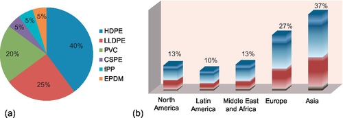
Due to good physical-chemical-mechanical and environmental characteristics of the geomembranes, their production and sales are rapidly increasing worldwide, as shown in Figure 8.4 (Polyethylene, 2014).
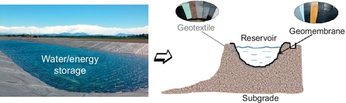
Geomembranes have been used in some of the largest hydroelectric and dam reservoir projects in the world. Hydroelectric power plants can require very large reservoirs. Water reservoirs are often lined with geomembranes to avoid leakage and erosion (Figure 8.5). High-density polyethylene (HDPE) and linear low-density polyethylene (LLDPE) geomembranes are effective and affordable options in reservoirs for water storage.
Geomembranes can provide an impermeable barrier for water retention that is superior to concrete or asphaltic lining in both cost and lower permeability. They are relatively impermeable in the range 1 × 10− 12 to 1 × 10− 15 m/s, which is three to six orders of magnitude lower than the typical clay liner.
Critically important for the proper design of geomembrane-lined side slopes of reservoir is the soil-to-geomembrane shear strength. Geomembranes can also be made from the impregnation of geotextiles with asphalt, elastomer, or polymer sprays, or as multilayered bitumen geocomposites.
The basic use of geomembranes should be their retention of liquids/solids over a long time, and they need to have high endurance properties. One of the best additives for plastics to resist ultraviolet (UV) degradation is carbon black. Black geomembranes will get very hot when exposed to sunlight because they absorb sunlight radiation. They will have more expansion/contraction due to temperature variations. New, innovative technologies enable the implementation of the different geomembranes (white geomembranes). In addition to having esthetic advantages, the reflective liner will also reflect solar radiation and reduce the temperature of the geomembrane.
Another innovative solution is an electrically conductive geomembrane (in which electrically reactive carbon is incorporated) that, once installed, can be rigorously tested for spark ruptures and leaking through the geomembrane.
For any technological application, geomembranes must have certain properties in order to satisfy demanding requirements for their safe use (Figure 8.6).

In order to maintain their function, geomembranes’ test methods and standards (e.g., ASTM and ISO) are available or are being developed by standards-settings organizations around the world.
There are important factors to consider when deciding which type of geomembrane to use in a water storage application. Table 8.2 presents the physical, chemical, mechanical, and other properties for the selected geomembranes.
Table 8.2
Properties of Different Types of Geosynthetics
| Propertiesa | Type of Geosynthetics | ||||||
| HDPE | LLDPE | EPDM | PVC | fPP-R | fPP | CSPE-R | |
| Physical | |||||||
| Water tightness | ✓✓✓✓ | ✓✓✓✓ | ✓✓✓✓ | ✓✓✓✓ | ✓✓✓✓ | ✓✓✓✓ | ✓✓✓✓ |
| Flexibility | ✓ | ✓✓✓ | ✓✓✓✓ | ✓✓✓✓ | ✓✓ | ✓✓✓ | ✓✓ |
| Elasticity | ✓ | ✓ | ✓✓✓✓ | ✓ | ✓ | ✓✓ | ✓✓ |
| Tensile strength | ✓✓✓✓ | ✓✓✓ | ✓✓ | ✓✓ | ✓✓✓✓ | ✓✓✓ | ✓✓✓✓ |
| Permeability | ✓✓✓✓ | ✓✓✓ | ✓✓✓ | ✓✓ | ✓✓✓ | ✓✓✓ | ✓✓✓ |
| Chemical | |||||||
| Chemical resistance | ✓✓✓✓ | ✓✓✓ | ✓✓✓ | ✓✓ | ✓✓✓ | ✓✓✓ | ✓✓✓ |
| Resistance to hydrocarbons | ✓✓✓ | ✓✓ | ✓ | ✓✓ | ✓✓ | ✓✓ | ✓ |
| Resistance to plasticizer extraction | ✓✓✓✓ | ✓✓✓✓ | ✓✓✓✓ | ✓ | ✓✓✓✓ | ✓✓✓✓ | ✓✓✓✓ |
| Root resistance | ✓✓✓✓ | ✓✓✓✓ | ✓✓✓✓ | ✓✓✓ | ✓✓✓✓ | ✓✓✓✓ | ✓✓✓ |
| Resistance to microbiological attack | ✓✓✓✓ | ✓✓✓✓ | ✓✓✓✓ | ✓✓ | ✓✓✓✓ | ✓✓✓✓ | ✓✓✓✓ |
| Mechanical | |||||||
| Dimensional stability | ✓ | ✓ | ✓✓✓✓ | ✓✓✓ | ✓✓✓✓ | ✓✓✓ | ✓✓✓✓ |
| Multiaxial strain | ✓ | ✓✓ | ✓✓✓✓ | ✓✓✓ | ✓✓ | ✓✓✓ | ✓✓ |
| Resistance to settlements | ✓✓ | ✓✓✓ | ✓✓✓✓ | ✓✓✓✓ | ✓✓ | ✓✓✓ | ✓✓ |
| Seamability | ✓✓ | ✓✓✓ | ✓✓✓✓ | ✓✓✓ | ✓✓✓✓ | ✓✓✓ | ✓✓✓ |
| Seamability to cold temperatures | ✓ | ✓ | ✓✓✓✓ | ✓ | ✓✓✓ | ✓✓✓✓ | ✓✓✓ |
| Seam testing | ✓✓✓✓ | ✓✓✓✓ | ✓✓✓✓ | ✓✓✓✓ | ✓✓✓ | ✓✓✓✓ | ✓✓✓ |
| Puncture resistance | ✓✓ | ✓✓✓ | ✓✓✓ | ✓✓✓ | ✓✓✓ | ✓✓✓✓ | ✓✓✓ |
| Surface friction | ✓ | ✓ | ✓✓✓✓ | ✓✓✓ | ✓✓✓ | ✓✓✓ | ✓✓✓ |
| Slope stability | ✓✓ | ✓✓✓ | ✓✓✓✓ | ✓✓✓✓ | ✓✓✓ | ✓✓✓ | ✓✓✓ |
| Repairability | ✓✓ | ✓✓✓ | ✓✓✓ | ✓✓ | ✓✓✓ | ✓✓✓ | ✓ |
| Service life | ✓✓✓✓ | ✓✓ | ✓✓✓✓ | ✓ | ✓✓✓✓ | ✓✓✓✓ | ✓✓✓✓ |
| Other | |||||||
| Environmental properties | ✓✓✓✓ | ✓✓✓✓ | ✓✓✓✓ | ✓ | ✓✓✓✓ | ✓✓✓✓ | ✓✓✓ |
| Easy of installation | ✓✓ | ✓✓ | ✓✓✓✓ | ✓✓✓✓ | ✓✓✓ | ✓✓✓ | ✓✓✓ |
| Details, design and installation | ✓ | ✓✓ | ✓✓✓ | ✓✓✓ | ✓✓ | ✓✓✓ | ✓✓✓ |
| Conformance to substrate | ✓ | ✓✓ | ✓✓✓✓ | ✓✓✓ | ✓✓ | ✓✓✓ | ✓✓✓ |
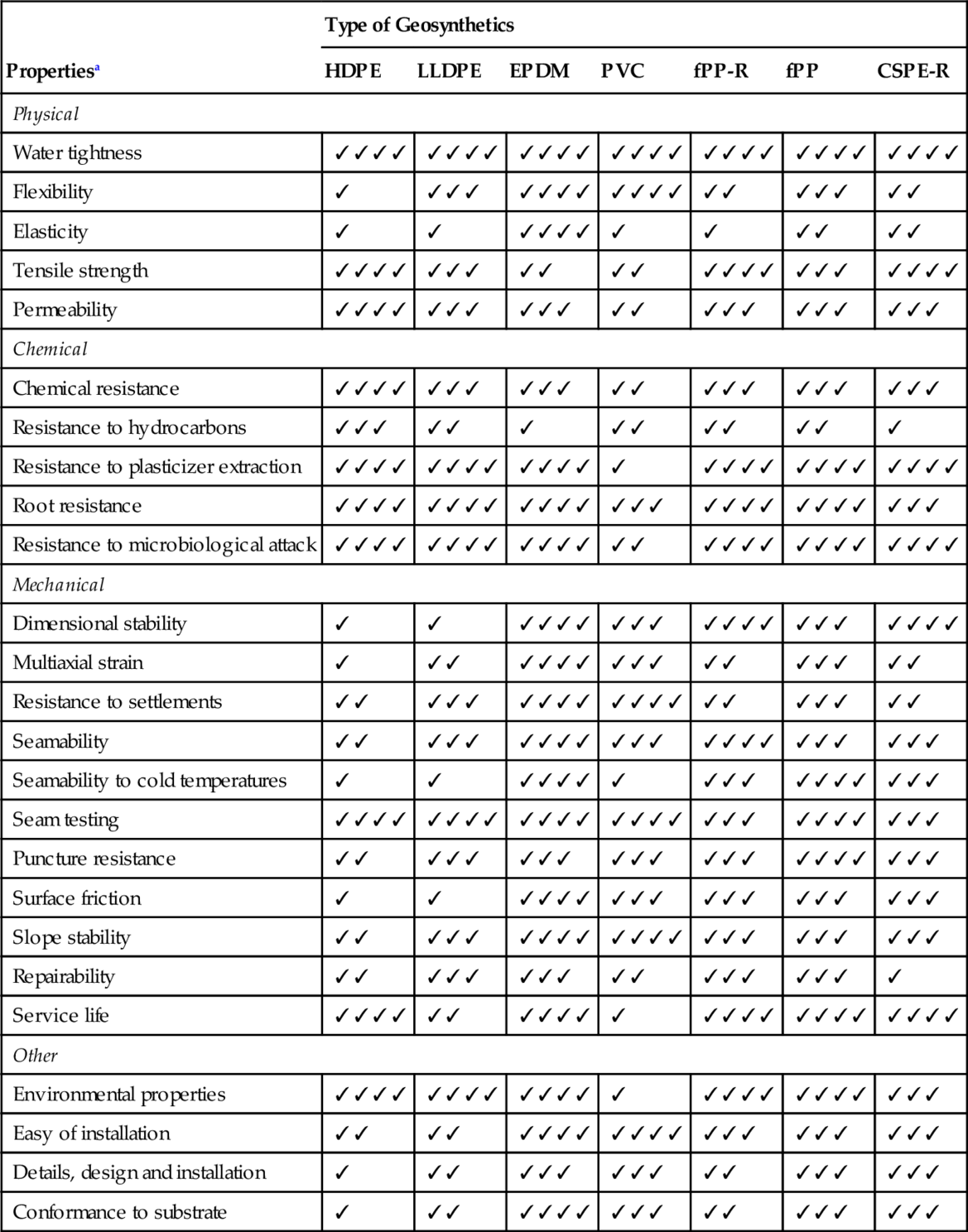
HDPE, high density polyethylene; LLDPE, linear low density polyethylene; EPDM, ethylene propylene diene terpolymer; PVC, polyvinyl chloride; fPP-R, flexible polypropylene reinforced; fPP, flexible polypropylene; R-CSPE, chlorosulfonated polyethylene reinforced.
a ✓✓✓✓ Excellent, ✓✓✓ Good, ✓✓ Fair, ✓ Poor.
The geomembrane properties are most involved with resistance or susceptibility to tear, puncture, and impact damage in thickness. For this reason, many agencies require a minimum under any circumstance (e.g., in the United States, minimum thickness is 0.5 mm; in Germany, for similar applications, minimum thickness is 0.75 mm). The lifetime of geomembranes is very long—about 25-30 years. HDPE geomembranes can far outlast other engineering materials in comparable situations.
8.3.2 Reservoir Volume
Before selecting the geomembrane type, the desired liquid volume to be contained versus the available land area must be considered. Such calculations are geometric by nature and result in a required depth on the basis of assumed side slope angles. For a square or rectangular section with uniform side slope, the general equation for volume is
where
H = average height (i.e. depth) of the reservoir (m)
W = width at ground surface (m)
L = length at the ground surface (m)
S = slope ratio (horizontal to vertical).
8.3.3 Hydro Energy Storage
Hydro energy that is stored in the reservoir can be calculated according to
where V (m3) is water volume in the upper reservoir, HTE (m) is total elevation difference between the lower and upper water levels, g (m/s2) is gravity acceleration, and ρ (kg/m3) is water density.
8.4 Concept Integration of the SE-PSH System
A concept-integrated SE-PSH system that uses natural resources (i.e., sun, gravity, seawater (in the case of PSH with seawater), and precipitation) is shown in Figure 8.7.
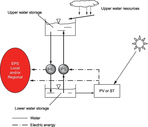
As shown, SE in PV and ST generators is converted into electrical energy, which is supplied to the pump station (PS), by which the water is pumped from the lower to the upper reservoir, which serves as water/energy storage. In the same reservoir, rain harvesting technology brings water from rainfall.
When there is demand for energy, the water is discharged from the upper to the lower reservoir, and the hydroelectricity to generate electricity is delivered to a local or regional EPS.
In this way, the possibility of a continuous energy supply to local consumers (i.e., SE-PSH) may enable EPS to give energy continuously.
8.5 Optimization Model of SE-PSH System
It is particularly important to determine the required size of the SE-PSH system and it is possible to optimize a model that takes into account all relevant parameters of the system (local climate, terrain configuration, mode of energy consumption, etc.).
8.5.1 Water Balance
The upper reservoir basically represents daily and seasonal energy storage that can balance summer surpluses and winter shortages of SE. However, its charge and discharge dynamics (water volume change from one time period i − 1 into the other i) are dependent on the inputs and outputs of water in the reservoir. Therefore, the dynamics for time stage i can be expressed by the water balance equation
providing that
where V(i) and V(i − 1) are water volumes in the upper reservoir in time steps i and i − 1, respectively; VNAT(i) is the volume of natural watercourses flowing into the upper reservoir (rivers, precipitation, etc.); VART(SE)(i) is the volume of artificial watercourses created by the pumping system (PS), which is generated by the energy from the solar generator; R(i) is the volume of rainfall falling into the upper reservoir; VRH(i) is the volume of rain harvesting technology that comes into the upper reservoir; VEV(i) is the volume of evaporation from the surface of the upper reservoir; VHE(i) is the volume of water discharged to the turbines to produce electric energy; and VMIN and VMAX are the minimum and maximum water volume in the upper reservoir, respectively.
8.5.2 Water Storage of PSH as Energy Storage of SE Generator
According to Glasnovic et al. (2013), interrelations between the value of the optimal nominal electric power of the SE generator and the working volume of the PSH upper reservoir, V0, can be calculated from the following expression:
where Ψ and Ψ* are parameters on the basis of location characteristics and technological features, and V0 is the operating volume of the upper reservoir.
Therefore, after determining the optimal values of the nominal electric power of the ST generator, V0 can be determined from the expression
From the operating volume V0 and reserve volume Vr of the upper reservoir
the required total size of the upper reservoir of PSH can be easily determined:
8.5.3 Model Formulation
Considering the fact that this is a multistage process in terms of time and that the objective and constraint functions are nonlinear in relation to decision variables, the most appropriate model is based on dynamic programming that uses the simulation-optimization model. Optimization is performed by dynamic programming, which is well adapted to the characteristics of the problem, while the necessary constraints are solved by simulation.
The elements of the mathematical simulation-optimization model are shown in Figure 8.8. The system inputs are controlled and uncontrolled (natural), while outputs are also uncontrolled. They are variable in time according to the state of the system and its surroundings. This means that the processes within the system can be represented in relation to time, introducing time stage i.
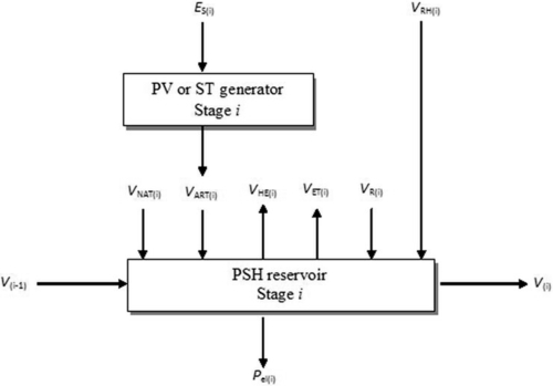
According to Glasnovic et al. (2013), the general formula of nominal electric power of the solar generator (PV or ST) can be calculated:

where ρ is the water density (ρ = 1000 kg/m3) and g is the gravitational constant (g = 9.81 m/s2); HTE(i) is the average total head (water level difference in upper and lower storage plus hydrodynamic losses in the pumping system (m)); ηSE is the efficiency of the collector field of solar power plants; ηPSI is the efficiency of the pumping system and inverter; Rcoll is the ratio of mean daily irradiation of tilted plane of tracking parabolic collectors and horizontal plane (for PV generator Rcoll = 1); ES(i) is the mean daily radiation on the horizontal plane (terrestrial radiation); VART(SE)(i) is the artificial water inflow, the daily water quantity pumped from the lower into the upper reservoir by the solar generator; and i is the time stage (increment).
Thus, power consumption of the integrated solar-hydro system, for a given manometer height and efficiency, depends on the ratio of the amount of water that solar power can pump and mean daily irradiation on the horizontal plane. This means that higher consumer energy consumption will require greater amounts of water to be pumped into the upper reservoir VART(SE)(i), and that the specific size of the solar radiation ES(i) (with certain specific local conditions) would be proportional to the needs and higher rated power of the solar generator Pel(SE)(i).
The system state has already been described by the corresponding balance Equation (8.1), while oscillations of the upper reservoir level are shown in Equation (8.2). This type of constraint also entered the initial conditions and requirement that the reservoir be full at the beginning of the observed period:
In that sense, the period with maximum available of solar energy should be taken as the starting point of the calculation. In view of the condition of sustainability of the whole system, the reservoir should also be full at the end of the observed period:
where VN is reservoir volume in the last time stage.
The decision variable constraint is linked to the motor/pump unit capacity (i.e., the appertaining pipeline), and can be expressed as follows:
where VART(MAX) is the maximum amount of water that can be pumped by the motor/pump unit (m3) in a certain period of time.
As Eck and Zarza (2006) showed that solar collectors produce thermal power for direct nominal irradiance values above 250 W/m2, it is necessary to introduce the constraint of minimum average daily solar irradiation of about 2 kWh/m2 day, which can be expressed as (Glasnovic et al., 2013)
In addition to these constraints, it is necessary even to introduce a limit to the amount of water that can lead to the upper reservoir of PSH technology rain harvesting VRH(i), which is governed by the surface that provides ground/land around the PSH technology as follows:
where VART(R)(MAX) is the maximum amount of water that may accumulate geosynthetics at a location along the upper reservoir of PSH.
The general model for determining the optimal power of the solar PV or ST generator (i.e., PV or ST power plant), when integrated with the PSH, can be written with recursive formulas of the optimization process by dynamic programming: (Glasnovic et al., 2013)

with constraints and time step i:

where fi (V(i)) is the optimal return function per state variable V(i) in time stage i, and f(i − 1)(V(i − 1)) is the optimal return function per state variable V(i − 1) in time stage i − 1. In Equation (8.16), (a) is actually Equation (8.1); (b) is Equation (8.7); (c) basically represents the constraint that applies only to the ST power plant (not to the PV power plant), where it operates on irradiated SE of 2 kW/m2/day (Glasnovic et al., 2011); (d) limits the amount of water that can give rain harvesting technology VRH(i) between the minimum (zero) and maximum VRH(MAX) value; (e) is the state variable constraint (water volume in the upper reservoir) between the maximum VMAX and minimum VMIN value; (f) is the condition that the first time stage V1 equals the last VN; that is, at the beginning and the end of the period, the reservoir volume is maximum VMAX (keeping in mind that the calculation should not be done as usual in calculating the storage hydro power plant (i.e., from the beginning until the end of the year, when there is a rainy period when the hydro reservoirs are full), but calculation should start from July 1 and finish with the same date, because at that time there is maximum SE and hydro reservoirs will be full); and (g) is the control variable constraint, i is time stage (increment), and N is the number of time steps.
8.6 Impact Geosynthetics and Dynamic Charging and Discharging of PSH System
8.6.1 Ratio P, V0, and Surface of Geosynthetics
The relationship between the PV and ST generators and working volume of the upper reservoir is given in Equations (8.3) and (8.4). However, if geosynthetics are involved in system “rain harvesting” technology, then this relationship changes, as shown in Figure 8.9 for ST and PV generators.
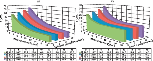
This can be explained by the fact that the capture of solar energy by ST power generator is weaker in winter (for several months, ST generator practically does not work because there is a lower threshold of solar radiation, i.e., 250 W/m2, Eck and Zarza, 2006), and the energy produced by the ST generator is more stochastic than the energy produced by the PV generator.
8.6.2 The Dynamics of Charging and Discharging the PSH System
It is particularly interesting to observe the dynamics of charging and discharging the upper reservoir in the case of different working volumes V0, which are shown in Figure 8.10. For this purpose, the observed changes in the working volume are from 10% to 90% in steps of 10% for both cases, respectively, and for PV-PSH and for ST-PSH systems; see Figure 8.10.
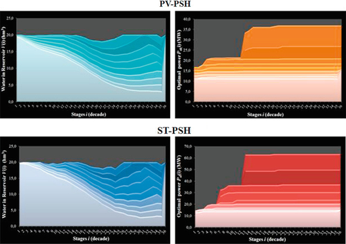
As shown, PV-PSH systems have a smoother transition from one time step to another compared to ST-PSH systems, which can also be explained by greater stochastic energy production from the ST generator. On the right side of Figure 8.10, the trends of increasing optimal nominal power generators are visible. As expected, the optimal nominal power ST generators are larger than the necessary PV power generators for the same reason that ST generators are inferior to PV generators in winter.
8.7 Conclusion
It is evident that at the present stage of PSH technology, it has advantages over other storage technologies, primarily because it can be stored up to the largest amount of energy, with relatively little cost and very little impact on the environment.
Therefore, PSH technology could play an important role in integrating the generators, which should connect the serial (SE-PSH-EPS), thus ensuring continuous energy supply throughout the year. Specifically, the fact that the weather conditions are repetitive throughout the year (annual cycles), as well as the fact that PSH technology can balance summer surpluses and winter shortages of energy, provide PSH technology with a significant advantage in terms of integration with solar generators.
But the factor that could have a significant impact on the greater use of integrated SE-PSH systems is geosynthetics, or new technology geomembranes that could create conditions for the construction of a reservoir on virtually all locations where there is a height difference. Geomembranes can retain water/seawater over a long time, and they have high endurance properties. Using carbon black additives, geomembranes become resistant to UV radiation. Innovative technologies are presented with white geomembranes, which can reflect solar radiation and reduce their temperature. Another innovative solution is an electrically conductive geomembrane (in which electrically reactive carbon is incorporated) that, once installed, can be rigorously tested for spark ruptures and leaking through the geomembrane.
The new area of application of integrated SE-PSH systems could be along the coast, or PSH with seawater that does not need the lower reservoir; thus, these systems can be expensive. Because the world population is migrating to the shores of the sea, the systems with PSH could be increasingly applied.
If geosynthetics is used as rain harvesting technology, then the entire SE-PSH system can significantly reduce the power, which could also have a significant impact on reducing investment in such a system.