
In this chapter
Flash is a powerful tool for creating anything from simple animations to interactive applications and simulations. It is also well suited for creating user interfaces for external data and streaming media. Its support for creative expression and practical programming, with a strong developer base, makes Flash an appealing tool to work with. The Flash authoring environment is the program in which you work to create Flash projects. You can use it to create several file types. The first is an editable document that contains your graphics and code for Flash. You create a Flash document by choosing File, Save from the menu bar. When you first save the file, giving it a name avoids the default filename of untitled-#. The .fla suffix is automatically added to the filename of the new document. You should keep this document in case you need it at a later time, as you most assuredly will. It’s known as a source file, and is pronounced “eff el ay” or sometimes as “flah.”
The published, compressed, ready-for-the-Web document that you produce from your .fla document is called a .swf file (pronounced “swiff”). This document wraps the contents of your Flash document into a single package that can be played either by a standalone Flash player or by any browser that has the Flash Player plug-in installed. Create it from the saved .fla file by choosing File, Publish Settings to open the Publish Settings dialog box, choosing .swf from the Format tab, and then clicking the Publish button. The .swf is automatically published to the same directory as the .fla file.
For a more advanced project, you might use an ActionScript document (.as), which is an external (to the .fla document) text file that holds a set of ActionScript code that can be included for use in the final published product. An .as document is also known as a source file. Both .fla and .as files are known as source files because they can be edited and are not part of the published result.
Before you dive into the details of everything Flash has to offer, you need to know a few more common terms that you will see throughout this section of the book. When a Flash file is being used in the authoring environment, it’s called author-time. When the published .swf file is running in a player, it is called run-time. Whenever I discuss file size or the importance of creating small files, I’m always discussing the .swf file and not the .fla document. The .swf is the final compressed file that will actually be downloaded and processed on the end user’s computer.
Now that you understand the basic areas of the program, it’s time to start exploring the many ways Flash can help you turn out a powerful and dazzling product.
This section is aimed at readers who are already familiar with Flash. If you are new to Flash, you might want to skip ahead to the next section.
This release includes a lot of really great stuff. Whereas the last release was said to have been mostly aimed at developers, this one should make both designers and developers very happy. Improvements and access to the “expressive” capabilities have been made throughout the interface as well as with ActionScript.
You can now apply graphic effects filters to text, movie clips, or buttons on the stage. These effects include glow, bevel, and drop shadow. Figure 8.1 shows a movie clip before and after the bevel filter has been applied to it. You can apply the filters with the Filters menu, which is grouped with the Property inspector whenever an object that can have filters applied to it is selected (see Figure 8.2).

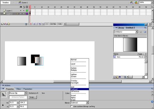
The new blend modes let you blend the colors in overlapping movie clips to create composite images. Modes include multiply, lighten, darken, add, subtract, difference, alpha, and invert. Figure 8.3 shows a movie clip without a blend mode next to two overlapping movie clips with the invert blend mode applied to one of them.
If no movie clips or images are located below the blended movie clip, it blends with the stage color.
Blend modes can be applied to a movie clip with the Property inspector (see Figure 8.4).
The radial gradients have been improved and now enable you to move the focal point of a gradient on the shape to which it’s applied to. You can also have more stops (colors) in the gradient, and you have a choice of spreading methods (pad, reflect, and repeat).
The Fill Transform tool has been replaced and expanded with the Gradient Transform tool (see Figure 8.5). It gives you much more control over how gradients are applied to shapes. Additionally, gradients and bitmap fills can now be applied to lines, which are also known as strokes, without requiring that they be converted to fills.
In Flash 8, you have more control over the strokes you draw than ever before. In previous releases, strokes were limited to a maximum size of 10 pixels. This maximum size has now been increased to 200 pixels, which is plenty of room to take advantage of the new feature just mentioned: the capability to color strokes with a gradient fill.
You can now also choose how lines are joined (miter, round, or bevel, as shown in Figure 8.6). Caps, which are the end points of lines that are not joined, also have new settings available (none, round, and square, as shown in Figure 8.7). All of these settings enable you to draw more cleanly and precisely, and can be set in the Property inspector.


Normally in Flash, when you draw a shape and then another that overlaps the first shape in the same layer, the two shapes meld into one. This is considered normal behavior that helps keep the file size down by not accounting for additional points when shapes overlap. However, Flash 8 gives you a new option for drawing shapes on the stage. When the new Object Drawing model is turned on, which you can do with the button at the bottom of the Tools panel, it creates new objects that don’t meld with other objects when you draw on the stage (see Figure 8.8). This new option is found in the Line, Oval, Rectangle, Pen, and Pencil tool options. I like to think of it as a kind of “auto-grouping” mode.
This is a sticky option for all of the tools that use it, which means that after you turn it on, it stays on for all tools until you turn it off. Object Drawing is turned off by default when you first enter the program. Although it remains to be seen what effect this will have on overall file size, you might want to try this option if you have worked extensively in “grouping” analogy illustration applications such as FreeHand.
Be aware that you need to double-click the drawing object on the stage to enter into edit mode for that object so that you can edit the actual shape, color, or other properties of the vectors that make up a drawing object created while in Object Drawing mode. Shapes drawn in normal mode are editable without double-clicking. To return a Drawing Object to behaving like a regular shape (with no need to double-click and edit), select it and choose Modify, Break Apart. The shapes will now be merged.
In MX 2004, the Undo feature was locked at the Document level, which meant that you had to work back through the history of every step in the document no matter on what timeline they occurred. In this version, to the joy of many, Object-Level Undo is back. With Object-Level Undo mode, each object on the Stage and in the library has its own undo list. As a result, you can once again undo changes to one object without affecting any other object.
However, the default setting for undo remains at the Document level and follows the History document changes. To turn on Object-Level Undo, go to Edit, Preferences (on a PC) or Flash, Preferences (on a Mac). In the General Preferences tab, select Object-Level Undo from the Undo options.
Flash 8 offers better text rendering with FlashType, which integrates subpixel rendering technology. This makes text, especially at smaller fonts, much more readable than it has been before now. Another improvement to text in this release is the addition of Bitmap Text Scrolling, which uses the bitmap surfaces capability to provide high-speed text scrolling.
In addition, improvements in the WYSIWYG text display enable you to have a more uniform experience of your text as it appears in the authoring environment versus how it appears when the .swf file is played in the Flash Player. In other words, what you see in the authoring environment is much more like what you get in the published .swf.
Macromedia has made a number of significant improvements to Flash’s performance with this release. Movie clips and vector images are now represented as cached bitmaps to improve rendering performance. When complex vector images or multiple instances of the same image with different effects applied are cached as a bitmap, every frame doesn’t have to be redrawn from the vector data. Chapter 9, “Working with Vector Artwork, Bitmaps, and Static Text,” explores the difference between vector and bitmap images in more depth.
Flash 8 introduces features for code development and run-time access to expressive features with ActionScript. These include the following features:
For those less experienced with coding, there is a new Script Assist mode in the Action panel.
Previously, you could dynamically load external JPEG files during run-time. Now you can also load external PNG and GIF files.
ActionScript 2.0 now has the capability to handle file uploads and downloads with user intervention.
The BitmapData API lets you manipulate images at run-time at the pixel level. This means that new filters and blend modes can be applied with ActionScript.
New features for media and components include an all new video codec and the new FLVPlayback component.
The new On2 Video Codec (VP6) offers huge improvements for web-based video. It features better control of video quality and data rates.
The FLVPlayback component makes it easy to import and integrate video into your Flash project.
The new Video Exporter enables you to convert video files to FLV (Flash Video format) files through the use of a special external application that is installed along with Flash. The Video Exporter also allows batch processing, which speeds the workflow enormously for large projects.
Now that you’ve gotten an overview of what’s new in Flash 8, it’s time to dig into the details and learn how to make the most of Flash.
The Flash authoring environment comes with a great number of tools for both creative and coding tasks. These tools are grouped into panels. You can customize the way these panels are arranged and even hide or reveal them to suit your needs.
Why have more than one panel set? Most people who work with Flash are involved in both design and coding. A developer might want different panels open when coding than when designing to limit the clutter of tool menus and icons on the desktop.
In previous releases, the task of saving and managing the workspace layout was handled with Panel Sets. These have been improved and are now found at Window, Workspace Layout, which provides options to open a saved layout, save the current layout, and manage the layouts.
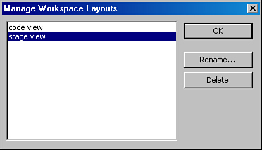
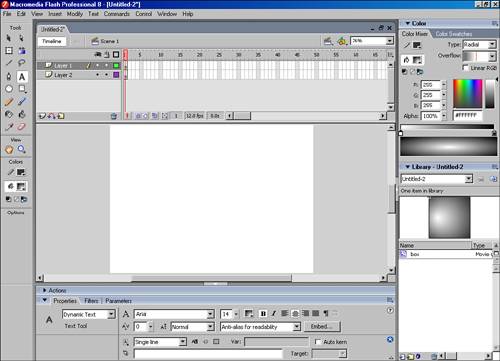
When you get a panel layout that you like, you can save and name it. In the Manage Workspace Layouts interface (see Figure 8.9), you have the option to rename or delete a layout you’ve already saved. Figure 8.10 shows the default layout of the Flash Workspace.
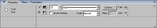
The Property inspector is located at the bottom of the Workspace and is used to control the properties of the tools and objects in Flash. The Property inspector is context dependent, which means that at any given time, it displays only the properties available to the element you’ve selected. For example, as shown in Figure 8.11, if you draw a shape with the Oval tool, the Property inspector gives you access to the fill color, stroke color, stroke thickness, stroke style, and custom settings for the stroke.
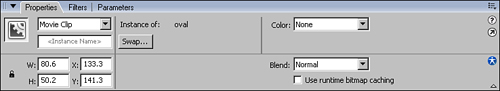
However, if you select a movie clip symbol instance on the stage, you get access to the symbol type (behavior), the instance name, and color effects that can be applied to the instance (see Figure 8.12). If you expand the movie clip Property inspector, you also get access to the width and height of the clip as well as its x and y positions relative to the registration point of the parent timeline.
When the tool selected does not have specific properties available, the Property inspector defaults to the document properties. For example, the Eraser tool does not have any properties that are listed in the Property inspector, so when it is selected, the Property inspector shows the document’s properties.
You have a lot of freedom to position panels, as suits your work habits. Panels can be docked or free-floating, and can even be moved from one docked location to another.
Panels can be dragged with the handle in the panel’s upper-left corner. To collapse a panel, click on the collapse arrow/button at the top-left corner of the panel or the arrow/button centered above the panel group in the horizontal splitter.
The panels in Flash work the same as they do in all Studio applications, although a few panels are unique to Flash and are covered here.
The Color Mixer panel offers many tools for selecting colors for fills and lines (see Figure 8.13). Color types include solid color, linear gradient, radial gradient, and imported bitmaps. In previous versions, these types could be applied only to fills. In Flash 8, you can now apply these color types to lines as well.
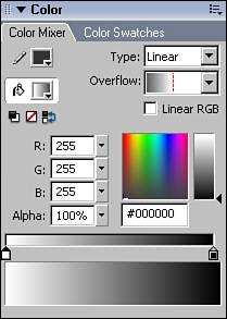
You can select your color from the color mixer in different ways:
From a palette of web-safe colors
By numerically setting RGB and Alpha values
By using the color picker with accompanying saturation level selector
You get experience with the color mixer in the coming chapters, especially Chapters 9 and 10, “Animation Basics.”
Filters are special effects or design shortcuts. They can be applied to objects from the Filters panel, which is grouped with the Property inspector at the bottom of the workspace.
Filters can be applied to text fields, movie clips, and buttons, either alone or in combination with other filters. They can be added to or removed from an existing object at any time in the development and design process. The available filters include the following:
Drop shadow
Blur
Glow
Bevel
Gradient glow
Gradient bevel
Adjust color
Combinations of filters can be saved as presets, which can be renamed or deleted.
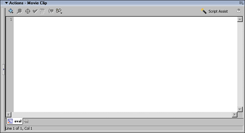
When working in the Flash authoring environment, you write and edit ActionScript in the Actions panel. To open the Actions panel (see Figure 8.14), go to Window, Development Panels, Action, or use the F9 keyboard shortcut.
Flash documents have various properties that you can set with the Document Properties panel. You can open this panel by choosing Modify, Document from the top menu bar or by clicking the Size button in the Property inspector while it is in its document context (click in the gray work area or an unoccupied stage area to get it to switch). The Property inspector is in document context by default. When tools or objects are selected, the context of the inspector shifts to the selected tool or object.
The Document Properties panel offers several properties that you can set:
Title is new to this version. Its value is embedded as metadata in the published
.swffile. This metadata is designed for use by search engines.Description is also new and embedded in the
.swffile as metadata that will eventually be used to help with content indexing for search engines.Dimensions are the width and height of your Flash movie/application. They determine the size of the stage for your project.
Background Color is the color of your Flash document’s stage.
Frame Rate sets the number of frames for the player to play per second. Frame rate impacts the quality of animation and the size of the published file. The greater the frame rate, the better the quality, but the larger the file size.
Ruler Units are part of the Dimensions property of the document. If you start out with Dimensions in pixels and then change the Ruler unit to inches, Flash converts the pixel value to inches value automatically. Although pixels are the standard measurement unit for web documents, the available Ruler Units options include Inches, Inches (decimal), Points, Centimeters, Millimeters, and Pixels.
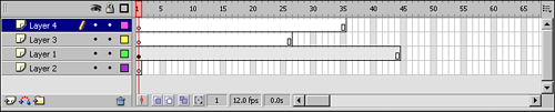
The timeline, shown in Figure 8.15, is basically a visual navigation tool and storage device that provides access to all the elements in your Flash project. It is basically a graph in two dimensions. Time (expressed in frames running from left to right) is placed along one axis, and content (stored in layers stacked on top of each other) is placed along another axis. You can access any particular point in time and space of your movie by clicking on that point in the timeline.
To understand the timeline, a basic understanding of animation is helpful. Animation works by showing a series of visuals that change over time. Slight differences in each image can make it appear as though the drawn object is moving. In Flash, each change in the visual information occurs at a certain time that is referred to on the timeline as the frame number. The visual change that occurs on that frame number can occur on one or many different layers in the document in a storage device called a keyframe.
So, much like a music score, the change over time is graphed on the horizontal scale with frame numbers, and the visual (or code) elements in the document are stored on the vertical axis as keyframes. Every keyframe in every layer at a certain frame number is played simultaneously. This is discussed more in Chapter 10, which covers animation and the basic elements of Flash.
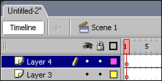
As important as the timeline is to organizing the overall project, it can consume precious screen real estate that can often be dedicated better to creating the content of each keyframe during author-time. In previous versions of Flash, you could collapse the timeline. In Flash 8, you can now completely hide the timeline in the authoring environment with a button interface under the tab with the filename at top of the document panel (see Figure 8.16).
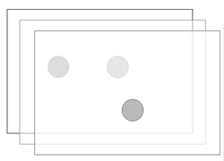
You can think of a movie as a stack of transparent sheets that you have painted with the elements of your animation (see Figure 8.17). If you were to look through the stack of sheets, you would see the painted areas of the sheets below, as long as they were not covered by an area where the sheet above it is painted. In Flash, rather than use sheets of transparent paper, you use layers.
One thing that often confuses new Flash authors is the stacking order of layers in a Flash movie. In a Flash movie, the stacking order matches the spatial order—in other words, the closer the layer is to the top, the more above the stage it will be. The bottom layer on the timeline is always the closest layer to the stage visually. You can think of the stage as a desk on which the stack of sheets is sitting. The sheet on top of the stack is the farthest from the surface of the desk.
Dragging one layer above another changes the stacking order of layers. You can also select several layers and drag them at once.
To add a new layer, click on the Add Layer button at the bottom-left corner of the timeline. You can also add a new layer by right-clicking on the name of an existing layer, and selecting the Insert layer from the context menu. To delete a layer, you can click on the Delete button or right-click on the layer’s name and select Delete Layer.
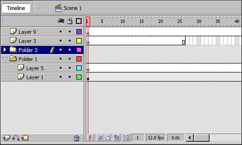
Layer folders can help keep layers organized when a project gets big or complex. You can use them to group related layers into a folder that can be expanded or collapsed as you work (see Figure 8.18). You can drag any layer into or out of any folder after the folder has been created. If you select multiple layers into a folder, their order before being moved is maintained in the folder.
Sometimes the references to frames in Flash can get a bit confusing. As mentioned previously, frame numbers on the timeline tell you where you are in terms of time in an animation. Frames are represented visually on the timeline as rectangular boxes with nothing in them. Frames add time for the content of a keyframe to play. Their only function is to play whatever the previous keyframe (to their left) contains.
A keyframe is a frame that stores a reference to content on the stage that occurs at that frame number and on that layer. Keyframes that include graphic content are represented by a filled circle on the timeline.
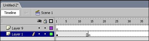
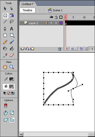
A blank keyframe is represented by an open circle in a frame (see Figure 8.19). This is a keyframe without any visual content. Blank keyframes also serve as a place for code to be attached so that it runs when the playback reaches that particular frame. A blank keyframe therefore is a good place to store your frame-based code. Keyframes with code attached always have a small letter a above them to let you know they contain code.
Onion skinning is a viewing mode that lets you see the previous frame while drawing in a new frame. The term comes from traditional animation techniques, which used “onion skin” paper that was thin, like the layers of skin on an onion. The paper allowed the animator to see through the layers of drawings as they worked on them.
This sounds a lot like working with layers, so what’s the difference between layers and onion skinning? With layers, you see everything that is on all the layers at a certain point in time as if looking through a single stack of transparent sheets. With onion skinning, you view the visuals in keyframes for more than one frame at a time.
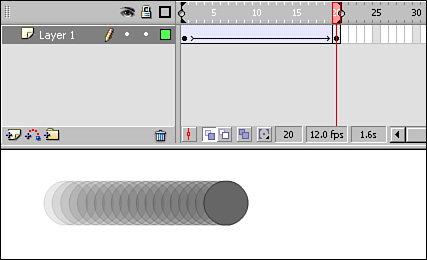
Onion skinning is not visible when you publish your .swf file; it’s just an author-time tool. You can toggle any of the onion skinning options on and off at any time in the authoring environment with buttons on the bottom of the timeline. Figure 8.20 shows onion skinning turned on for a short animation. The position of the circle at each frame is visible on the stage at once. If you use the outline option for onion skinning, just the outlines of the visual elements for each frame are visible, except for the frame currently being edited. If you’d like to have more than one frame available for editing at once, set the Edit Multiple Frames option, which makes all keyframes within the onion markers. To set the onion markers (the brackets on the number line of the timeline) drag the brackets along the timeline.
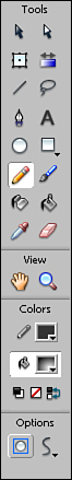
The Tools panel contains the basic visual creation tools that come with Flash (see Figure 8.21). Each tool has its own properties, which can be accessed with the Property inspector panel.

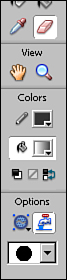
Below the tools is a small interface that enables you to quickly change the color of the stroke or fill of any tool you select. You can select the colors before using the tool. Many tools offer additional options in the bottom section of the toolbox when you select the tool.
The following sections describe each tool as well as give keyboard shortcuts (capitalized letters in parentheses) that you can use. Keyboard shortcuts can help you save time and develop a smooth workflow when you get comfortable with them. If you are accustomed to the keyboard shortcuts of other applications, you can customize your keyboard shortcuts in Flash to match those shortcuts. To view the default setting, go to Edit, Keyboard Shortcuts (on a PC) or Flash, Keyboard Shortcuts (on a Mac). This brings up the Keyboard Shortcuts dialog box, where you can select the shortcuts of another application and apply them to Flash or define your own custom set of shortcuts.
At the top of the tool panel, you’ll find the Arrow tools: the Selection tool (V) and the Subselection tool (A) (see Figure 8.22).
The Selection tool (V) is the black arrow, and it lets you directly grab, select, and move any element on the stage. To select an object, just click on it. Double-clicking selects any contiguous parts of a shape. To add to a selection, hold the Shift key down while you select. To remove elements from your selection, hold the (Option) [Alt] key while you select. After a selection has been made, simply hold the mouse down and drag the selection to a new place to move the elements.
You can also drag in any blank area of the stage to create a selection marquee to include an entire shape. However, be aware that when you are using the normal drawing mode in Flash, if you miss a portion of a shape when you are using this method of selection, you cut the shape.
Approaching any deselected vector shape with the mouse cursor enables you to manually edit that shape by dragging and pushing the unselected outlines and fills. It’s as if you are selecting the space around the shape, and pushing that space into the shape, like pushing on a water balloon. The indicator for the tool changes depending on whether you are over a corner or a curve point. To move a corner point, drag to a new location. Hold the (Option) [Alt] key while dragging to place a new corner point. Pull in the middle of any line portion to create a curve point. This is covered in more detail in Chapter 9.
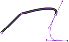
The Subselection tool is the white arrow with black outline (A). It enables you to view and manipulate the points of any vector object. Select any line and drag the corner points or change the selected curve points by manipulating the Bezier handles (see Figure 8.23). Vector objects and Bezier handles are discussed in later chapters.
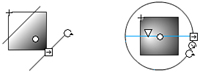
With the Free Transform tool, you can change the dimensions of a selected object by dragging the handles at its sides or corners (see Figure 8.24). In addition, you can rotate the object by positioning the mouse a little outside the corner handle of the shape or object. The rotation usually occurs around the center of the selection, but you can adjust the center of rotation by dragging the white dot in the middle of the selection to another position.
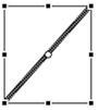
You can manipulate the horizontal or vertical skew of a selected object by dragging from somewhere between any of the rotation and scale points. Drag in the direction you want the shape to skew (lean).
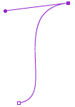
When a shape is selected while the Free Transform tool is in use, the Envelope and Distort options become available in the lower options. These options give you additional control points that you can use to distort the shape. Use curve points for both the Distort option and the Envelope option. Figure 8.25 shows the Free Transform tool applied to a line, with the Envelope option turned on. One of the control points has been used to create a curve in the previously straight line.
As mentioned in the “What’s New in Flash” section, in Flash 8 the Fill Transform tool has been expanded into the new Gradient Transform tool. It can be used for both gradient transformations and to manipulate bitmap fills. Note that a gradient or bitmap fill must be present on the stage and selected before you can use the Gradient Transform tool on it.
Flash offers two types of gradients: Linear and Radial. You can choose which type of gradient you want to use, as well as the colors for them, in the Color Mixer panel and add them with the Paint Bucket tool. (Both the color mixer and the Paint Bucket tool are discussed later in this chapter.) A linear gradient transitions from one color to another in one direction. A radial gradient transitions from the center of one color out to another color. When you have your gradient fill, you can transform the scale, location, and rotation of the gradient with this tool (see Figure 8.26). In addition, the focal point of radial gradients can now be adjusted.
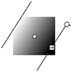
The Gradient Transform tool also enables you to manipulate a bitmap fill’s size and rotation. Flash 8 also enables you to manipulate the tiling skew of bitmap fills.
The Line tool lets you draw by clicking on a start point and then dragging to the endpoint of the line you want to draw (see Figure 8.27). Turn on the Snap to Objects option to see a circle indicator appear when you approach other objects and want to easily and precisely connect the line to that object. In Flash 8, you can also turn on an additional cue called Stroke Hinting in the Property inspector to give you a preview of where your line will interact with other lines.

The Lasso tool (see Figure 8.28) lets you define and select an odd-shaped area by drawing the selection. This is especially useful when working with bitmaps that are broken apart or traced, which is discussed in more detail in Chapter 9. The Lasso tool has a Magic Wand option that selects areas of like colors in broken-apart bitmaps. It does not function for any vector shape.

The Pen tool enables you to draw complex illustrations by manually creating corner points and curve controls that make up your drawing (see Figure 8.29). To begin your drawing, create corner points by clicking on the stage and create curve points by clicking and dragging in the direction you want the curve to grow. To complete your drawing, double-click at the last point in the drawing, or close the shape by clicking on the beginning point.
The Text tool lets you place text fields on the stage (see Figure 8.30). After a new field has been placed, you can modify its properties with the Property inspector. You can set an alpha value (the transparency level) for the text with the Text (Fill) Color property. You can also add any of the filter effects discussed earlier in the chapter by selecting the field and choosing the Filters tab in the Property inspector group.
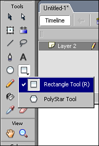
After the Oval or Rectangle shape tool is selected, you can draw the shape by clicking and dragging on the stage. Features of the shape, such as line thickness and color, can be preset with the Property inspector before you draw your shape on the stage.
A PolyStar tool is also available to create a more complex shape. You can access it by clicking on the little black triangle in the bottom-right corner of the Rectangle Tool button (see Figure 8.31). In the Property inspector, you can find additional options for the PolyStar Tool, including an option to create a polygon or a star, the number of sides, and the angle at the points.
The Pencil tool is a freeform drawing tool that lets you draw lines and curves that follow the movement of the mouse as you drag it across the stage. The accuracy of your drawing is controlled by the Smoothing option in the lower part of the toolbox. You can choose from the following options:
Straighten—. Straight lines only
Smooth—. Smooth lines that hide small inaccuracies created during drawing
Ink—. Exactly what you draw
Usually you will want to use the Smooth option to keep the number of points you draw down and with that the file size. In Flash, keeping the file size small is a concern because larger sizes take longer for the end user to download. Figure 8.32 shows a line drawn in the Ink mode next to a line drawn in the Smooth mode of the Pencil tool. Drawing in Flash is discussed in more detail in Chapter 9.

Although the Brush tool (see Figure 8.33) is similar to the Pencil tool in how it draws, it is different in that the Brush tool draws fills (shapes without outlines). The Pencil tool draws lines. The Brush mode, which is set in the toolbox options, enables you to set how your brush stroke fills in the space when other graphic elements are already present. For example, you can set it to Paint Behind to have your stroke visible only where there are no existing lines or shapes. The strokes are there, and are visible if you later move the covering objects. This is discussed in more detail in Chapter 9.

You can use the Paint Bucket and Ink Bottle tools (see Figure 8.34) to change the colors of graphic elements that you’ve already drawn. The Paint Bucket tool adds a fill to a closed shape. A closed shape is a shape that has an outline with no breaks.
The Ink Bottle tool enables you to change the properties of strokes (outlines) instead of fills. You can also use the Ink Bottle tool to add an outline to an existing shape that does not currently have an outline.
The Eyedropper tool enables you to sample the color of a fill or line and then apply it to another object with the Ink Pot or Paint Bucket tools. When dealing with a stroke, the Eyedropper tool also collects the line width and stroke type information to be added to the new line.
The Eraser tool can come in handy because it lets you erase previously drawn graphic elements. The tool has several settings in its options, which are available on the lower toolbox when it is selected:
Erase Normal erases both fills and outlines.
Erase Fills erases only the fills and leaves outlines untouched. The eraser stroke can start at any point.
Erase Lines erases the lines but leaves fill areas untouched.
Erase Selected Fills lets you select a fill to which you want to apply the eraser before you begin erasing. Only the selected fill is affected; adjacent fills are left intact.
Erase Inside lets you start the erase from inside an outlined shape. Then you can proceed as if with Erase Fills, but this time, it leaves fill areas outside of the outline intact. It’s sort of a manual knock-out. Unlike the Erase Fills option, for a fill to be erased in this option the eraser stroke must start inside of the fill shape that is being erased.
The Eraser tool also has a Faucet option, which lets you select and delete a single element (based on color selection) at once (see Figure 8.34). This can save a lot of time when cleaning up traced bitmaps.
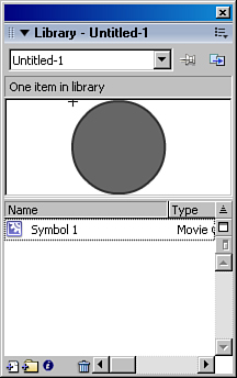
The Library is one of the most important features in Flash. As you will learn in Chapter 10, the Library stores and organizes all the assets in your project that can be reused.
Whenever a symbol is created or imported, it’s automatically added to the Library (see Figure 8.35). Even if you later delete that symbol from the stage, it remains in the Library. Symbols in the Library can also be accessed with ActionScript and attached to the stage at run-time.
Why won’t the Paint Bucket fill in the shape I drew with the Pencil tool?
Check to see whether there are any gaps in the outline of the shape you are attempting to fill. When the gaps are closed and the shape is completely enclosed, you should be able to apply a fill.
Why doesn’t the Gradient Transform tool do anything when I click on a shape with it?
Make sure there is a gradient or bitmap fill in the shape. The Gradient Transform tool can be applied to only existing gradient or bitmap fills.
Why doesn’t my .swf file show up when I publish or test my movie?
Make sure that you have saved your .fla document before you publish or use Control, Test Movie to create your .swf file. You have to save the .fla first so Flash knows where to save the .swf file and what its name should be.
When you start learning Flash, it can be frustrating and sometimes overwhelming. Be patient. Take your time, keep practicing, and be sure to play. Explore the tools without a project deadline; just experiment with what you can do with Flash.
To experiment without danger of losing what you’ve already created, get in the habit of implementing simple version control for your projects by using Save As with a new filename, rather than using Save whenever you make changes to a file. This way, you can revert to an earlier version if you make a mistake. If you’re working as part of a team that uses a formal version control system, you can still follow the naming convention in your shop while adding suffixes for your own local file versions.