
In this chapter
Did you ever play with a Lite-Brite as a child? If so, that may have been your first experience with creating bitmap graphics, albeit at very low resolution. Resolution refers to the number of dots of color, or pixels, that are squeezed into a display screen. With a Lite-Brite, the resolution is about 20 dots per square inch. On the other hand, the resolution on a typical high-resolution desktop monitor is 1024 by 768. That’s 768 lines of dots, with 1024 dots in each line. Obviously, the resolution on a computer screen is much greater than that of the colored pegs on a Lite-Brite board; however, the concept is much the same. Individual dots of color are arranged on a grid to form an image. On a computer screen, the image is rendered for display as an array of pixels.
There are two main phases in the life of a digital image: how it is displayed and how it is stored. Both vector and bitmap graphics are displayed in the same way on the monitor with the resulting physical screen image rendered pixel by pixel. The difference between “bitmap” and “vector” refers to how the data describing the image is stored. In a bitmap format, the data is saved as a grid of dots, whereas a vector format saves the data as patches of color defined by geometrical formulas.
Each format has its strengths and weaknesses. Bitmap graphics format the information needed to display an image pixel by pixel. As a result, the files can take up a lot of space, but they don’t require much processing before output to the monitor’s screen. Vector graphics files, on the other hand, are considerably smaller, but can be processing intensive because they have to be converted from a math formula into the grid of colored dots displayed on the screen.
To better understand the difference between bitmaps and vectors, consider an example. Figure 9.1 shows a blue square that is 30 pixels by 30 pixels. Saving that image as a bitmap would require data for each one of the 900 (30×30) pixels that make up the blue square.

On the other hand, vector graphics use lines and curves to describe the areas on the screen where particular colors should be. The only data you need to save for a square is its size and position in the document (as x and y coordinates) and the function that describes it as a square. The graphics rendering program can evaluate the function describing that square and fill in the appropriate pixels. More complex shapes can be described by more complex functions.
In Figure 9.2, the dark blue dots represent how many points of data are required to save the same blue square in bitmap format and in vector format. As you can see, for simple shapes, vector graphics require less memory, so they are ideal where file size is an issue, as in when you have limited disk space or file transfer speed limitations.

Figure 9.2. Bitmap graphics require more information to describe a simple shape than vector graphics require to describe the same shape.
However, as the graphics get more complex, vector formats can take up even more memory than a bitmap version of the same image. More complex vector graphics require more anchor (or key) points to define areas of color (see Figure 9.3), and the more anchor points used to describe a shape, the larger its file size becomes. One of the benefits of the vector graphics file format is that it’s a description of a shape rather than a list of all the pixels that fit into that shape; therefore, it takes up less file space. If you add more anchor points to your description of the square, not only does it increase the number of points saved, but it also increases the number of times a formula is used to draw the shape.

Why care about file size? The bigger the file, the longer it takes for the end user to download it. Even though Internet download speeds continue to increase, remember that Flash is also used on mobile devices with smaller memory capacity and slower processing speeds than desktop and laptop computers.
In addition to file size, vector graphics have the advantage of scaling well. Bitmaps do not. Bitmapped data describes the image as fixed to a grid of a particular size. In vector graphics, the key anchor points are relative, so the functions can accommodate scaling without losing image clarity. Figure 9.4 shows an enlarged bitmap and an enlarged vector graphic.
Bitmaps can add visual depth and texture to your Flash project. Used in moderation, they can make all the difference in your visual design. They can also be the focus of an application, as in a slide show or picture gallery. Flash supports several bitmap file types, including JPEG, GIF, and PNG. If you have Quicktime installed, you can also import PSD, TIFF, and SGI files.
There are a couple of ways to bring bitmaps into your Flash project: Import them to the library or directly to the stage. To import to the stage choose File, Import, Import to Stage and select the file you want. You can also open an external library and drag the image to the stage.
When authoring with Flash, you should be concerned about file size. Bitmaps can bloat your project, but you can shave off some of that file size within the Flash authoring environment.
In the library, right-click on the bitmap name and select Properties, or click on the Properties icon (the white i with a blue circle around it) at the bottom of the library panel. This brings up the Bitmap Properties panel (see Figure 9.5).
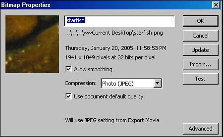
To compress the bitmap with the Bitmap Properties panel, uncheck the Use Document Default Quality option. Then select a compression type, check the Allow Smoothing option, and choose either Test or Update. The Photo (JPEG) compression setting results in lost pixels, so be sure to save a version you can revert to before proceeding. The Lossless PNG/GIF compression setting is best for traced bitmaps (see the next section) or bitmaps with simple shapes and few colors. You can achieve significant file size improvements with this technique. If your imported bitmap has already been compressed, you might want to go with the PNG/GIF option. If you’ve got a JPEG without any previous compression, you might want to go with double compression. This is something with which you need to experiment. There’s a delicate balance between file compression and artistic integrity. If you overcompress your bitmap images, they will look terrible.
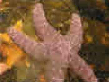
There may be times when you need to work with a logo or flat artwork in a Flash project. You might receive this artwork as bitmap files that are smaller than you need for your project. As discussed previously, you can end up with ugly pixilated images if you resize them larger than the originals. Figure 9.6 shows a bitmap image that’s been enlarged and looks pixilated.
In such a case, it might be best to trace the bitmap. By using the Trace Bitmap command, you can convert a bitmap into a vector image. To trace a bitmap, Select its instance on the stage and then, from the main menu, go to Modify, Bitmap, Trace Bitmap to open the Trace Bitmap panel (see Figure 9.7).
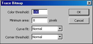
When tracing bitmaps, there are several parameters to set. Each of these options enables you to control the quality of the resulting image and optimize for file size:
Color Threshold—. This setting determines how much color detail is preserved. The lower the threshold (from 1 to 500), the more colors are used.
Minimum Area—. This setting determines how many pixels should be included in the area for normalization. During a trace, the continuous range of colors in a bitmap is replaced with discrete areas of colors. The lower the minimum area, the more detailed the traced image will be.
Curve Fit—. This setting determines how closely the traced curves follow the original image.
Corner Threshold—. Much like curve fit, the corner threshold determines how precisely the traced image follows the original image.
If you set your resolution high with these four parameters, be prepared to wait a while. It’s very processor intensive.
Recall how the data is organized in a bitmap image: as a grid of colored dots (or pixels). When Flash traces a bitmap, it converts the data, pixel by pixel, and simplifies it into shapes of color bounded by lines and curves, essentially converting the bitmap into a vector graphic (see Figure 9.8).

Because tracing a bitmap results in complex shapes, it is important to reduce the complexity and smooth out the curves of these shapes when working with traced bitmaps. Smoothing the curves reduces the number of anchor points needed to describe the shapes in the image. This process is called optimization.
To optimize the curves of a traced bitmap, select the image or a portion of the image, and use the Optimize Curves panel by choosing Modify, Shape, Optimize. In this panel, you can set the level of smoothness desired, determine whether you want multiple passes to execute (which slows down the process, but can result in less distortion of the image), and indicate whether you want a report after the optimization is completed. If you’ve set the main toolbar to be visible in your workspace, you can click directly on the Smooth or Straighten buttons.
Note
I’m always looking for ways to keep the file size down, but sometimes traced images just look great! However, you’ve got to keep the end user in mind. Optimize those traces! A traced bitmap that hasn’t been optimized can result in an even larger file than the original bitmap.
Can you further optimize a traced bitmap without losing too much image quality? Of course! One technique to try is to use the selection tool to select a rectangular or oval area on the edge of the image. Then smooth the curves of the selected area. Large shapes can be selected individually and smoothed. This can be tedious work, but selective optimization can pay off with a much smaller file size.
Breaking apart bitmaps makes the pixels available to be edited in the Flash authoring environment while preserving the clarity of the bitmap image. You might find this useful if you want to change the color of certain parts of the image. After the bitmap has been broken apart, you can manipulate it with tools such as the Eraser and the Paint Bucket. To change the color of part of the image, select the original with the Lasso or Magic Wand tools, and fill the area with the new color.
Another use for breaking apart a bitmap is to knock out the background of a figure or object. Zoom in on the image to gain more precise control over what pixels are masked with the eraser tool. The process doesn’t actually get rid of the pixels and therefore doesn’t reduce the file size, so you may want to do your knock-out processing before bringing the image into Flash.
You can create original vector graphics with the drawing tools included in the Flash authoring environment. Remember that vector graphics use lines and curves to define areas of color? Well, in the Flash authoring environment, you can draw those lines and curves directly on the stage. The drawing tools let you set the properties of the lines (strokes) and the color areas (fills).
If you haven’t done so already, open Flash and create a new Flash document. Start drawing on the stage with the Pencil tool, which enables you to draw free-form lines. The pencil tool has three options that control how many line segments and curves your line has:
Straighten—. Use this option if you want to draw a straight line.
Smooth—. Use this option if you want to draw a curving line.
Ink—. Use this option if you want to draw a curving line, but keep in mind that the Ink option follows the movement of your mouse more exactly than the Smooth option and produces more segments and curves. This leads to a larger file size.
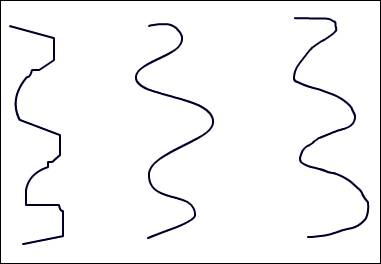
Figure 9.9 compares lines drawn with each of the three options selected.
Notice that when you draw an oval with the Pencil tool with the Straighten option selected, the shape snaps into a smooth oval when you complete the oval. This can help you quickly draw ovals. When the pencil options are set to Smooth or Ink, this snapping does not occur (see Figure 9.10).
In Flash, lines are often called strokes. You can control certain properties of the lines you draw with Flash such as stroke thickness and color. Flash gives you many options for drawing strokes, whether they are drawn with the Pencil tool or as an outline with a Shape tool (oval or square).
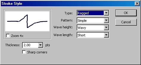
Depending on what stroke style you select, you get access to different properties with the Stroke Style Panel, which you can access by clicking on the Custom button in the Property inspector when using a tool with strokes (see Figures 9.11 and 9.12).
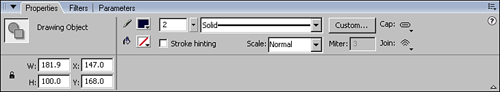
Although stroke styles can enhance the look of your design and save you time, be sure to use them carefully because they can increase the file size. A complex stroke style requires more information to describe the line to which it’s applied. In addition to stroke styles, lines also have options for line color and thickness, as well as cap and miter styles. You can set all of these options with the Property inspector.
Note
This is where terminology could be a little confusing: When you draw with the Paintbrush tool, you are drawing a shape, not a stroke. In the Flash authoring environment, the terms line and stroke are used interchangeably. For example, the Modify, Shape menu has an option to convert a Line to Fill, and yet there is a Stroke Style panel.
You can create a fill with the Paint Bucket tool by selecting the tool and a fill color and then clicking on the area you want to fill. For the Paint Bucket tool to work, the area must be a closed shape. Figure 9.13 shows a closed shape as well as a shape that is not closed.

When you draw a shape freehand with one of the drawing tools, you might accidentally leave a gap between curves. If you want to apply a fill with the Paint Bucket tool, you need to close the shape by drawing or stretching a line connecting the two ends on either side of the gap. If you still cannot fill the shape, look for additional gaps. You can use the drawing tool you started with, such as the Pencil tool, or another drawing tool.
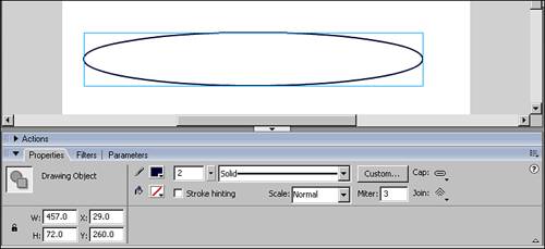
When the shapes you are drawing are simple, you can avoid problems with open shapes by using the Shape Tools (Oval, Rectangle, and Polygon). To use these tools, click and drag the mouse across the stage. The point where you initially click becomes the registration point for the bounding box of the shape. The farther you drag the mouse, the larger the shape becomes. The shape tools combine lines and fills, but you can set either the line or fill color to be empty. For example, the oval in Figure 9.14 was set to have the fill color be empty.
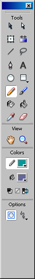
Try out the Brush tool. Whereas drawing with the Pencil tool creates lines, drawing with the Brush tool creates a fill (a shape). You need to use the Fill Color option to set the fill’s color. In addition to color, the Brush tool has Fill options and additional tool-specific options, including brush size and shape (see Figure 9.15). Brush shapes range from round and oval to square and slanted.

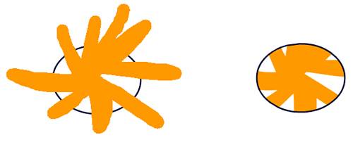
The Fill options let you paint inside of previously drawn shapes without worrying about precision. For example, if you want to fill a shape without going outside its outline, you can select the Paint Inside option. Begin drawing inside the shape, and your strokes will fill only the inside of the shape. If your mouse goes outside the shape, that area is not rendered on the screen when you release your mouse. Figure 9.16 shows a shape being filled with the Paint Inside Option selected. Note that while you are drawing, the color does show up outside the shape’s outlines, but when the mouse button is released, only the color inside of the shape remains on the stage. This technique can be used when you want to fill a shape with gaps.
The Paint Behind option lets you color outside of existing lines and shapes without covering them. You can start at any point on the stage, and the color is rendered automatically behind everything else already on the stage. Figure 9.17 shows an example of painting behind another shape.

In Flash, overlapping shapes and outlines merge and overwrite each other. This can be very useful when you want to chop up parts of an image or you want to sculpt a shape.
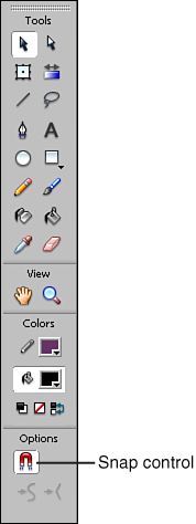
New to Flash 8 is the Object Drawing Model. When the Object Drawing option is turned on, the shape outlines do not affect each other. The main benefit of this is that you can select and move shapes and lines around without them getting chopped up in the process. Flash enables you to toggle Object Drawing mode on and off in the Options for a drawing tool (as shown in Figure 9.18) so you can go back and forth between the default and the Object Drawing mode. The button for toggling Object Drawing mode is located at the bottom left of the Tools panel.
A fill doesn’t have to be a solid color. It can be a gradient or even a bitmap. The Color Mixer panel gives you access to several methods of selecting a fill, as described in Chapter 8, “Introducing Flash 8.”
A gradient is a fill that transitions from one color to another, or through several colors, and can be either linear or radial. A linear gradient transitions from color to color in a single direction, whereas a radial gradient transitions out from a central point in all directions.
The Gradient Transform tool enables you to edit gradients. To access the Gradient Transform tool, select it from the Tools panel and then click on a shape or line filled with a gradient. Figure 9.19 shows the points of manipulation for a gradient. By dragging the manipulation points, you can control the center, focal point, width, size, and rotation of a gradient fill.
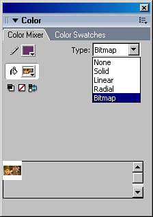
Bitmap fills are used to fill shapes with a bitmap image. The image can be used once, or tiled repeatedly inside of the shape. Used sparingly, bitmap fills can add depth and texture to your projects. To set a bitmap for a fill, select the Bitmap option for Fill Type in the Color Mixer panel, as shown in Figure 9.20, where the bitmap option is selected and highlighted in blue in the drop-down menu. A dialog box opens up where you can select a bitmap to import. Another method for setting a bitmap as fill is to select the Paint Bucket tool, click on a bitmap in your library, and then fill the shape with the selected bitmap.
In previous versions of Flash, lines had to be converted to fills before they could have gradients or bitmaps applied to them. In Version 8, you can apply a gradient or bitmap to a line and still have access to its stroke properties.
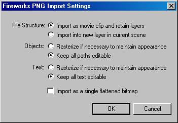
In addition to creating new vector graphics from scratch in Flash, you can import .swf and other vector graphics file formats that have been prepared in another program. For example, you can import a Freehand file and continue manipulating the curves in the Flash environment. To import an external image file, go to File, Import and select either Import to Stage or Import to Library. If you import a Fireworks PNG file that contains vector graphics, the Fireworks PNG Import Settings dialog box opens and enables you to select settings for how much information the file will bring into Flash about its vector shapes and layers (see Figure 9.21). Be sure to preserve layers and not flatten the image on import.
If you’re accustomed to drawing with tangible art supplies, drawing with a mouse can be a challenge. It’s not the same as the direct control you have with pen and ink or a paint brush. Fortunately, the Flash toolbox comes with handy tools for editing and adjusting shapes and lines.
Rather than try to draw a shape precisely with a mouse, try using the Smooth option or a shape tool (oval, rectangle, or polystar) and then modify it with either the Selection or Subselection tools. You can move the end points of lines and the corners of shapes. You can also drag a line at any point between its endpoints and alter the shape of its curve. If you think of drawing with Flash as something more like sculpting than sketching, you might find yourself warming up to the tool set. The idea is to start with a rough draft and then use the tools to continually fine tune your project until it’s the work of art you set out to create.
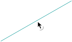
The Selection and the Subselection tools give you different ways to manipulate the curves of your drawing. The Selection tool (the black arrow) gives you direct access to the curve or endpoint of a line. To change a line’s curve, move your mouse toward the line until a curve icon appears beside your cursor, as shown in Figure 9.22. You can now click and drag the line, stretching it into a new shape. Go ahead and have fun playing with it.
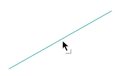
As you move your mouse toward the endpoint, a corner icon appears beside the cursor, as shown in Figure 9.23. When the corner icon appears, you can click and drag the endpoint to a new position on the stage.
The Selection tool also enables you to select or “pick up” a line or shape and move it. To move the entire line, first select it by clicking on it. When selected, a tight grid of dots overlays it as shown in Figure 9.24.

The Subselection tool (the white-filled arrow) is located to the right of the selection tool in the Tools panel. It gives you access to the Bezier handles and anchor points of the curve. By dragging a handle or anchor point with the Subselection tool, you can precisely control a curve’s shape.
The Straightening and Smoothing tools can help you improve the look of your image while greatly reducing its file size. Because vector graphics depend on defining shapes with formulas, and more complex shapes require more formulas, reducing the complexity of a shape reduces its memory space. Therefore, you can shave off a lot of space by straightening and smoothing lines and fills.
When you select a line or shape with the Selection tool, the Straightening and Smoothing tools become available in the options at the bottom of the Tools panel. To apply these tools, first select a line or shape and then click on either the Straightening or Smoothing tool. The Straightening tool simplifies selected lines by converting arcs into straight lines and corners. The Smoothing tool simplifies lines by reducing the number of anchor points in the curve.
Tip
After tracing a bitmap to vector format, use straightening and smoothing extensively. In fact, you can repeat each process until the image becomes too distorted and then undo it one or two times. This is best done in subsections of the image to avoid too much distortion of the overall image.
The more curves used to define a shape, the more complicated the vector formulas become and the larger the file size. By reducing the number of curves needed to define a shape, you’re optimizing the curves of that shape. As an alternative to the Smoothing and Straightening tools, you can optimize curves with the Optimize Curves dialog box (Modify, Shape, Optimize).
There are three text field types in Flash: static, dynamic, and input. Static text fields, and the text they contain, are created at author-time. Dynamic and input text fields and their contents can be created at author-time or at run-time with ActionScript. This section focuses on static text fields. The other types are discussed in detail in Chapter 16, “Putting It All Together: Creating an XML-Based Photo Slide Show.”
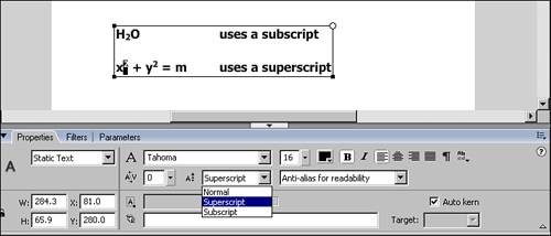
To create a static text field, click on the Text tool and then on the stage. This places a new text field on the stage, with a cursor ready to accept the input you type from your keyboard. You can set formatting options for text fields with the Properties inspector. These options include font, font size, color, and alignment. Additional options for text fields include changing the direction of text from horizontal to vertical. You can set the spacing between characters. By selecting individual characters in a static text field, you can also create superscript and subscript formatting (see Figure 9.25).
Static text fields can be given a URL link and target attributes, making the text object analogous to an embedded link in an HTML document. When a text field has a URL link, the background for the text is part of the hit area, which is the area that responds to the user’s mouse.
In the Flash authoring environment, you have access to all the fonts that are currently installed on your system. In an HTML document, only the name of the font is stored in that document. The fonts themselves are not included in the HTML file. For those fonts to appear on a user’s screen, the specified font must be on the user’s system. If it isn’t, the browser uses its default font instead. There are two options in Flash for ensuring that your text appears as you designed it, or at least close: embedding and device fonts. They both have advantages and weaknesses.
For static text, embedding is automatic. When a font is embedded, the outlines of the font are saved as vector shapes in the Flash file. Although this assures that the font you chose will always be the font that is displayed, each character adds to your project’s file size.
The other option is to use device fonts, which let you set a category of fonts for a text field, such as serif or sans serif fonts. The player then displays a font from the user’s system from that category. A sans serif font might be rendered as Helvetica on a Mac or rendered as Arial on a PC. The advantage of using device fonts is that you can keep your file size small while maintaining loose control over font types in your project. It’s a good idea to use device fonts when displaying large amounts of text.
To break apart text, select a text field on the stage and then go to Modify, Break Apart. Breaking apart text is different from breaking apart bitmaps. Flash breaks text apart in two steps. The first time, it breaks the text field into individual text fields for each character from the original field. This can add significant size to your file (more than doubling the size of the same text in a single text field). So why would you do this? Because the individual characters are then available to animate or apply individual effects to. This can produce some nice effects, but use it sparingly because it can bloat file size.
The second step of breaking apart text is to break apart a text field containing a single character and convert it into a vector shape that can be manipulated just as any other vector shape. You can create some unique font effects this way (see Figure 9.26).

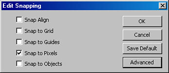
The placement of text on the stage affects how legible that text is in the published .swf file. If a text field is not aligned exactly on a whole pixel, the text appears blurry when rendered. For text to be clearly legible in Flash, modify the snapping settings to Snap to Pixels. You can change this setting by choosing View, Snapping, Snap to Pixel. You must turn off all other snapping options by selecting them in the same menu.
In previous versions of Flash, you had to open the menu repeatedly for each snapping option you wanted to change. Now there is a panel where you can edit all snapping options at once. Stage borders settings, object spacing, and center alignment are available through the Advanced button on the Edit Snapping interface, which you can open by choosing View, Snapping, Edit Snapping (see Figure 9.27).
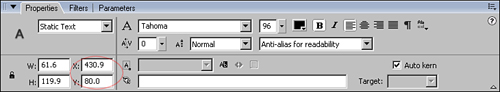
If you place a text field on the stage without using the Snap to Pixel option, you can still make sure that it is positioned on a whole pixel. Select your text field and go to the Property inspector. You can then round off the X and Y coordinates of your text field by directly changing their numerical values (see Figure 9.28). For example, if the X value is 362.9, you can round that up to 363.0. Even a change that small makes your text display more clearly.
In Flash, as with most word processors, you can control how the text is aligned in the text field. The text can be aligned to the left, center, or right, or justified across the entire field. Justified alignment spaces the text so that it is flush to the right and to the left, although there are irregular spaces between individual characters.
Left or right alignment gives you the clearest text. Center alignment and justified text can result in blurry characters because these formats can position characters off-pixel.
Anti-aliasing smoothes the outlines of text so that the edges look less jagged when rendered on the screen. However, when using smaller font sizes, some fonts appear clearer with anti-aliasing turned off (see Figure 9.27). To control the anti-aliasing setting for an individual text field, select the text-field on the stage and then turn anti-aliasing on or off in the Property inspector.
You don’t have to position everything by simply eyeballing it. Flash includes many aides to help you precisely position and size objects. These aides include snapping, grids, guides, guide layers, and the align tool.
Snapping helps position objects relative to each other and to the stage. When the Snapping option is turned on (see Figure 9.29), your object snaps into place when you position it close to its desired location. To set how objects snap, open the Edit Snapping interface by choosing View, Snapping, Edit Snapping, and select the snapping options you want (see Figure 9.29).
You can also adjust the Object spacing (how close the objects must be to a snapping guide for snapping to occur) and both the horizontal and vertical distance between objects in the Advanced area of the Edit Snapping interface (View, Snapping, Edit Snapping, Advanced), as shown in Figure 9.30. In previous versions of Flash, this was called snap tolerance.
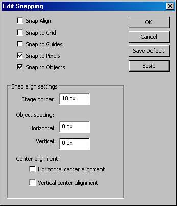
Figure 9.30. Open the advanced Snap Align options by clicking on the Advanced button in the Edit Snapping interface.
Remember that snapping is especially important for text fields because this affects readability. Flash renders text more clearly when it is aligned on a pixel. If the text is aligned on a half pixel, it appears blurry.
The grid consists of uniformly arranged vertical and horizontal lines. It sits behind all drawn elements on the stage, and is not rendered at publishing time. From the View menu, you can hide or show the grid. You can customize the spacing of grid lines by going to View, Grid, Edit Grid. You can also set the color of the grid lines in the same panel.
In addition to the grid, you can use a guide to show an element with which you’d like your object to interact at a later frame, or to mark the position of where the two will meet. You can convert any element on the stage into a guide by placing it into a guide layer or setting its existing layer as a guide. Just like the grid, guides and guide layers are not rendered at publishing time. Guide layers can be restored easily to a normal layer.
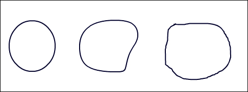
You can numerically set the height, width, and position of a selected design element in the Property inspector. For example, imagine that you draw an oval on the stage that is roughly 40 pixels high and 70 pixels wide, and draw another oval that is roughly 30 by 50 pixels. What if you want both ovals to be precisely 34 pixels wide? When you select an oval, its properties become accessible in the Property inspector and you can set its width to exactly 34 pixels. The shape on the stage resizes accordingly.
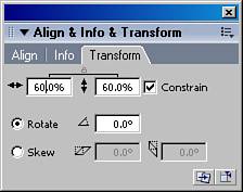
You can also select Window, Transform to set the scale as a percentage (see Figure 9.31). Check the Constrain box to set the scale for both dimensions (height and width) at the same time by an equal percentage. For example, if you want to reduce a shape by 50%, turn on Constrain and set the width scale to 50%. The height scale resets automatically to 50% as well.
The Align panel (see Figure 9.32) enables you to perform several positioning and sizing tasks, including Align, Distribute, Match Size, and Space. It can be your best friend, but be sure to pay attention to whether it’s set relative to selected symbols or to the stage. To apply the alignment options to objects on the stage, select the objects you want to align, open the Align panel by selecting Window, Align, and then click on one of the options in the Align panel. Shapes and symbols can be aligned on the left, right, top, or bottom edges, and can be centered vertically or horizontally.
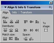
The Match Size options set the smaller objects to the same size as the largest object selected. Be careful, though: If you set this to be relative to the stage, you’ll have some very large objects. This is where the Undo button comes in handy.
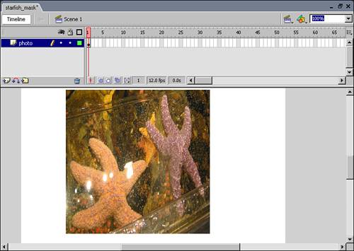
In Flash, using a mask is often called spotlighting. A mask is a shape in a layer that covers whatever is below it except for your defined area(s), functioning as the window through which the underlying image is seen. To help understand the concept, imagine that you have a photograph for which you want to make a quirky frame. You can take some fancy paper, cut an odd-shaped hole in it, and use this as a frame. When you place the paper on top of the photo, part of the photo shows through the hole in the paper.
To create a mask in Flash, first place an image on the stage (see Figure 9.33) and name its layer. It can be a vector graphic or an imported bitmap (see the previous section on importing bitmaps).
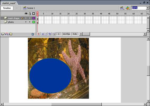
Next add a new layer above the photo layer and name it. Making sure that this new layer is selected, draw a shape over the image (see Figure 9.34).
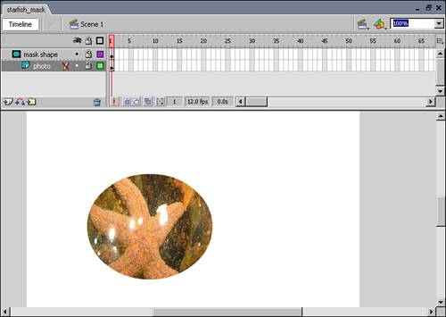
Now you’re ready to turn the new layer into a mask. Right-click on the layer you want to use as a mask and select Mask from the menu that opens. Your timeline layers should now be arranged as shown in Figure 9.35. Notice that the image is now hidden, except for the area covered by the shape.
You can also use text as a mask (see Figure 9.36). The process is the same as with any other mask, except that you use a text field in the mask layer instead of a shape.

You might be wondering whether you can animate the shape in the mask layer. Yes you can! More on that in Chapter 10, “Animation Basics.”
Why does my bitmap image look blurry?
If you enlarge a bitmap to a size greater than the dimensions of its size at import, it ends up with a pixilated effect. To avoid this, try to import the bitmap at the size at which you intend the image to be presented. If it’s a simple bitmap, such as a logo, try tracing the bitmap before you resize it. By converting the bitmap to a vector format, you make it better equipped for enlarging.
Why is my shape not accepting a fill?
Check to see whether your shape is closed. The Paint Bucket tool works in closed shapes only.
I selected my shape, but when I moved it, an outline was left behind.
When a shape has both a fill and an outline, both must be selected if they are to be moved together.
Once you become comfortable with the Tools in Flash, you may find that Flash is a great environment for quickly sketching out ideas. Whether you’re a designer, a coder, or a combination of the two, the ability to quickly draft the visual elements of a Flash application will serve you well.
The best way to get to know the tools in Flash is to practice. Try each tool, and see what you can do with it. Then try to accomplish a specific drawing task. If it’s not going well, set the project aside for a while and come back to it later.
If you’re accustomed to other graphics programs, try to suspend your expectations as you learn the Flash tools. One of the things I have come to treasure in Flash is the ability to directly select and interact with the visual elements in any layer that is visible on the stage.
Compared to other graphics programs I’ve used, Flash is more sculptural in terms of the artistic process. In fact, the only other applications I’ve worked with that have had more of a sculptural process have been 3D authoring tools. By sculptural, I mean that you can push and pull the parts. The parts can be nested within each other. They can also have mechanics inside of them (in the form of ActionScript).
While the possibilities of what you envision may outpace your skills for a while, be patient. With practice, your skills can indeed catch up to your visions in Flash.