6.4. Data Type Conversion
The Cortex®-M processors support a number of instructions for converting data between different data types.
6.4.1. Conversion of Data Size
On compilers for ARM® architecture, different data types have different sizes. A number of commonly used data types and its corresponding sizes on ARM compilers are shown in the following table (Table 6.7).
When converting a data value from one type to another type with a larger size, we need to sign extend or zero extend it. A number of instructions are available to handle this conversion (Table 6.8).
Table 6.8
Instructions for signed extend and zero extend of data values
| Conversion operation | Instruction |
| Converting an 8-bit signed data to 32-bit or 16-bit signed data | SXTB (signed extend byte) |
| Converting an 16-bit signed data to 32-bit signed data | SXTH (signed extend half word) |
| Converting an 8-bit unsigned data to 32-bit or 16-bit data | UXTB (zero extend byte) |
| Converting an 16-bit unsigned data to 32-bit data | UXTH (zero extend half word) |
If the data is in the memory, we can read the data and carry out the zero-extend or signed-extend operation in a single instruction (Table 6.9).
There is no need for additional store instructions to handle signed data because truncation of data values from 32 bit to 16 bit or 8 bit is done on the fly.
Table 6.9
Memory read instructions with signed extend and zero extend of data values
| Conversion operation | Instruction |
| Read an 8-bit signed data from memory and convert it to a 16-bit or 32-bit signed value | LDRSB |
| Read an 16-bit signed data from memory and convert it to a 32-bit signed value | LDRSH |
| Read an 8-bit unsigned data from memory and convert it to a 16-bit or 32-bit value | LDRB |
| Read an 16-bit unsigned data from memory and convert it to a 32-bit value | LDRH |
6.4.2. Endian Conversion
The memory system of a Cortex-M processors can either be in little endian configuration, or big endian configuration. The configuration is defined in hardware and cannot be changed by programming. Occasionally we might need to convert data between little endian and big endian format. There are several instructions to handle this, as listed in Table 6.10.
Table 6.10
Instructions for conversions between big endian and little endian data
| Conversion operation | Instruction |
| Convert a little endian 32-bit value to big endian, or vice versa | REV |
| Convert a little endian 16-bit unsigned value to big endian, or vice versa | REV16 |
| Convert a little endian 16-bit signed value to big endian, or vice versa | REVSH |
6.5. Data Processing
Most of the data processing operations can be carried out in very simple instruction sequence. However, there are situations that more steps are required. In here we will look at a number of examples.
6.5.1. 64-Bit/128-Bit Add
Adding two 64-bit values together is fairly straightforward. Assume that you have two 64-bit values (X and Y) stored in four registers, you can add them together using ADDS followed up ADCS instruction, as shown below:
  LDR   r0, =0xFFFFFFFF  ; X_Low ( X = 0x3333FFFFFFFFFFFF)
  LDR   r1, =0x3333FFFF  ; X_High
  LDR   r2, =0x00000001  ; Y_Low ( Y = 0x3333000000000001)
  LDR   r3, =0x33330000  ; Y_High
  ADDS r0, r0, r2 ; lower 32-bit
  ADCS r1, r1, r3 ; upper 32-bit
In this example, the result is in R1, R0, which is 0x66670000 and 0x00000000. The operation can be extended to 96 bit, 128 bit, or more by increasing number of ADCS instructions in the sequence (Figure 6.5).

6.5.2. 64-Bit/128-Bit Sub
The operation of 64-bit subtract is very similar to the one of 64-bit add. Assume that you have got two 64-bit values (X and Y) in four registers, you can subtract them (X − Y) using SUBS followed up SBCS instruction, as follows:
  LDR   r0, =0x00000001  ; X_Low( X = 0x0000000100000001)
  LDR   r1, =0x00000001  ; X_High
  LDR   r2, =0x00000003  ; Y_Low( Y = 0x0000000000000003)
  LDR   r3, =0x00000000  ; Y_High
  SUBS r0, r0, r2 ; lower 32-bit
  SBCS r1, r1, r3 ; upper 32-bit
In this example, the result is in R1, R0, which is 0x00000000 and 0xFFFFFFFE. The operation can be extended to 96 bit, 128 bit, or more by increasing number of SBCS instructions in the sequence as shown in Figure 6.6.
6.5.3. Integer Divide
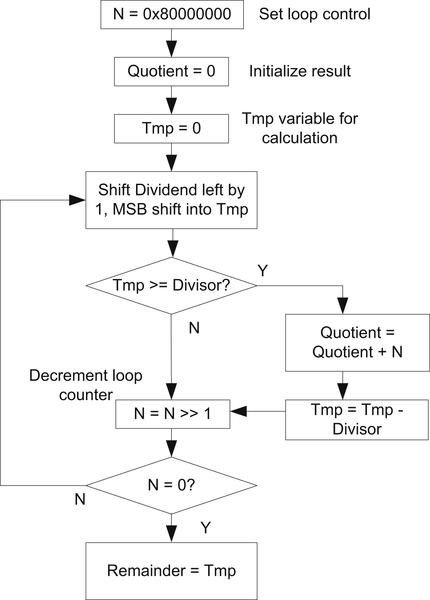
Unlike the Cortex®-M3/M4 processor, the Cortex-M0 and Cortex-M0+ processors do not have integer divide instructions. For users who program their applications in C language, the C compilers automatically inserts the required C library function that handles integer divide when needed. For some other users who prefer to write their application entirely in assembly language, they can create an assembly function like the following example (Figure 6.7), which handles unsigned integer divide:
The divide function contains a loop that iterates 32 times and compute 1 bit of the result each time. Instead of using an integer loop counter, the loop control is done by a value N which has 1 bit set (one hot), and shift right by 1 bit each time the loop is executed. The corresponding assembly code can be written as:

simple_divide
    ; Inputs
    ;   R0 = dividend
    ;   R1 = divider
    ; Outputs
    ;   R0 = quotient
    ;   R1 = remainder
    PUSH    {R2-R4} ; Save registers to stack
    MOV     R2, R0  ; Save dividend to  R2 as R0 will be changed
    MOVS    R3, #0x1 ; loop control
    LSLS    R3, R3, #31 ; N = 0x80000000
    MOVS    R0, #0  ; initial Quotient
    MOVS    R4, #0  ; initial Tmp
simple_divide_loop
    LSLS    R2, R2, #1 ; Shift dividend left by 1 bit, MSB go into carry
    ADCS    R4, R4, R4 ; Shift Tmp left by 1 bit, carry move into LSB
    CMP     R4, R1
    BCC simple_divide_lessthan
    ADDS    R0, R0, R3 ; Increment quotient
    SUBS    R4, R4, R1
simple_divide_lessthan
    LSRS    R3, R3, #1 ; N = N >> 1
    BNE     simple_divide_loop
    MOV     R1, R4 ; Put remainder in R1, Quotient is already in R0
    POP     {R2-R4}; Restore used register
    BX      LR     ; Return
This simple example does not handle signed data and there is no special handling for divide-by-zero case. If handling of signed data division is needed, you can create wrapper to convert the dividend and divisor into unsigned data first, and then run the unsigned divide, and convert the result back to signed value afterward.
6.5.4. Unsigned Integer Square Root
Another mathematical calculation that is occasionally needed in embedded system is square root. Since square root can only deal with positive numbers (unless complex number are used), the following example only handles unsigned integers. For the following implementation (Figure 6.8), the result is rounded to the next lower integer.
The corresponding assembly code can be written as:
simple_sqrt
    ; Input  : R0
    ; Output : R0 (square root result)
    PUSH    {R1-R3}     ; Save registers to stack
    MOVS    R1, #0x1    ; Set loop control register
    LSLS    R1, R1, #15 ; R1 = 0x00008000
    MOVS    R2, #0      ; Initialize result
simple_sqrt_loop
    ADDS    R2, R2, R1  ; M = (M + N)
    MOVS    R3, R2      ; Copy (M + N) to R3
    MULS    R3, R3, R3  ; R3 = (M + N) ˆ 2
    CMP     R3, R0
    BLS     simple_sqrt_lessequal
    SUBS    R2, R2, R1  ; M = (M - N)
simple_sqrt_lessequal
    LSRS    R1, R1, #1  ; N = N >> 1
    BNE     simple_sqrt_loop
    MOV     R0, R2      ; Copy to R0 and return
    POP     {R1-R3}     ;
    BX      LR          ; Return

6.5.5. Bit and Bit Field Computations
Bit data processing is very common in microcontroller applications. From the previous divide example code we have already seen some basic bit computation on the Cortex-M0/M0+ processor. In here we will cover a few more examples of bit and bit field processing.
To extract a bit from a value stored in a register, we first need to determine how the result would be used. If the result is to be used for controlling conditional branch, the best solution is to use shift or rotate instruction to copy the required bit in Carry flag in the APSR, and then carry out the conditional branch using a BCC or BCS instruction. For example,
 LSRS R0, R0, #<n+1> ; Shift bit “n” into carry flag in APSR
 BCS   <label>       ; branch if carry is set
If the result is going to be used for other processing, then we could extract the bit by a logic shift operations. For example, if we need to extract bit 4 in the register R0, this can be carried out by:
 LSLS R0, R0, #27 ; Remove un-needed top bits
 LSRS R0, R0, #31 ; Move required bit into bit 0
This extraction method can be generalized to support extraction of bit fields. For example, if we need to extract a bit field in a data with “W” bits wide, starting with bit position “P” (LSB of the bit field), we can extract the bit field using:
 LSLS R0, R0, #(32-W-P) ; Remove un-needed top bits
 LSRS R0, R0, #(32-W)   ; Align required bits to bit 0
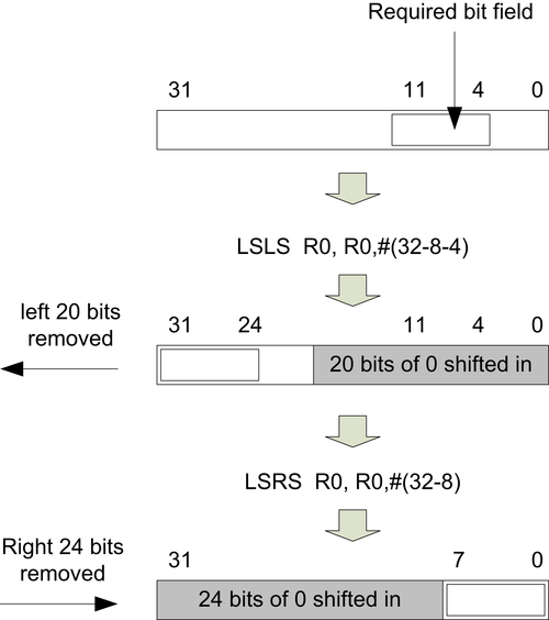
For example, if we need to extract an 8-bit width bit field from bit 4 to bit 11, we can use:
 LSLS R0, R0, #(32-8-4) ; Remove un-needed top bits
 LSRS R0, R0, #(32-8)   ; Align required bits to bit 0
The operation is illustrated in Figure 6.9.
In a similar way, we can clear bit field in a register by a few shift and rotate instructions:
 RORS R0, R0, #4        ; Shift unneeded bit to bit 0
 LSRS R0, R0, #8        ; Align required bits to bit 0
 RORS R0, R0, #(32-8-4) ; store value to original position
The operation is illustrated in Figure 6.10.

For masking of other bit patterns, we can use BICS (Bit Clear) instruction. For example,
 LDR R1, =Bit_Mask ; Bit to clear
 BICS R0, R0, R1   ; Clear bits that are not required
The “Bit_Mask” is a value reflecting the bit pattern you want to clear. The BICS instruction does not have any limitation of the bit pattern to be cleared, but it might require slightly larger program size as the program might need to store the value of “Bit_Mask” pattern as a word size constant.
..................Content has been hidden....................
You can't read the all page of ebook, please click here login for view all page.