18.2. Handling printf
18.2.1. Overview
Based on the examples in the previous section, we can create our own string printing function to handling printing of text strings, as shown below.
This works great for printing constant strings. We can also use this function to print other information by using sprint function to print the information to a text buffer, and then output it using UART_puts, the string output function we created:
However, it would also be useful if we can configure the “printf” function to use the UART directly, or talk to the debugger software in some way to display the messages we want to show. There are two techniques that can help to achieve this objective:
Retargeting—In most compilers, you can redefine certain low-level function(s) so that the message passed onto display in “printf” is redirect to peripheral(s) of your choice. This allows you to use a peripheral such as a UART or an LCD module to handle “printf” messages. In some tool chains, the retargeting feature might also support input function such as “scanf”.
Semihosting—In some tool chains, you can configure the compilation output to pass “printf” outputs to debugger connected to the microcontroller via the debug connection. Semihosting feature in some tool chains (e.g., ARM® DS-5) might also support accesses to file I/O and other system resources. It does not take any peripheral resources, but is limited to debug environments only.
Both retargeting and semihosting features are tool chain dependent. In the following section, we will cover the retargeting and semihosting with various tool chains.
18.2.2. Retargeting with Keil® MDK
In Keil MDK-ARM (or other ARM tool chains such as DS-5™ Professional), the function that needs to be implemented to support printf is “fputc”. Optionally, you can add a character input function “fgetc” for input function.
By adding the following file to your project, you can use printf for message output.
18.2.3. Retargeting with IAR EWARM
The same retargeting operation can also be done in the IAR Embedded Workbench for ARM environment.
| Low-Level I/O Functions | |
| Output | size_t __write(int handle,const unsigned char ∗buf,size_t bufSize) { size_t i; for (i=0; i<bufSize; i++) { send_data(buf[i]); } return i; } |
| Input | size_t __read(int handle,unsigned char ∗buf,size_t bufSize) { size_t i; for (i=0; i <bufSize; i++) { // Wait for character available while(data_ready() ==0); buf[i] = get_data(); // Get data } return i; } |
For example, in order to allow the printf messages to be output to the UART, the following “retarget.c” can be used:
If the project is not going to use any input functions from the C runtime libraries (e.g., scanf, fgets), then the __read function can be omitted.
18.2.4. Retargeting with GNU Compiler Collection
In GNU Compiler Collection (gcc), you can implement retargeting function to redirect printf to peripherals. In normal gcc, the redirection of text message output is handled by implementing a “_write” function.
Depending on the library setting for linking stage, you might also need to include additional stub functions to get it to work.
18.2.5. Semihosting with IAR EWARM
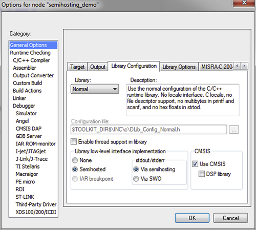
Instead of using a peripheral to handle message display, it is possible to use the debug connection to handle printf message display. For IAR Embedded Workbench for ARM, there is no need to add any special code to use semihosting. You only need to enable semihosting in the project setup as shown in Figure 18.5.
After the project is compiled, you can start the debugger as normal. Inside the debugger, the Terminal I/O window needs to be enabled. This can be accessed from the pull down menu: View → Terminal I/O. Once enabled, the printf messages will then appear in the Terminal I/O window, as shown in Figure 18.6. If your application includes any input functions from the C runtime library, you can also enter the input at the Input box of the Terminal I/O window.

Please note that in some cases, the semihosting operations can be quite slow and may require the processor to be halted frequently for the data transfers, it is not suitable for some applications that need real-time processing capability.
18.2.6. Semihosting with CoIDE
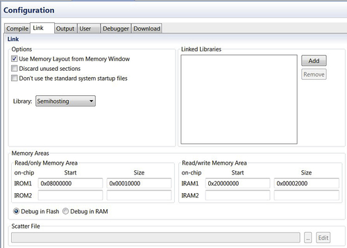
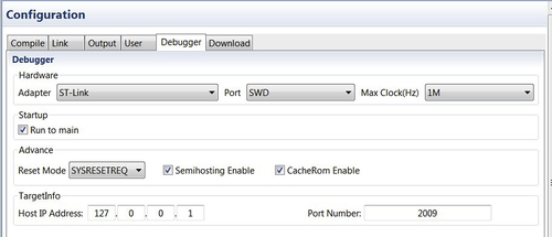
Semihosting is also supported in CooCox CoIDE. In order to use semihosting function for printf, you need to ensure that the semihosting library is use for the linking process (Figure 18.7), and in the debugger option tab the semihosting feature is enabled (Figure 18.8).
A modified C library component (syscalls.c) is needed to bridge between the C library and semihosting code. If you are using older versions of CoIDE (prior to version 2), you should also include a “Semihosting” software component in the project repository.
18.3. Developing Your Own Input and Output Functions
18.3.1. Why Reinventing the Wheel?
The C libraries provided a number of functions for text output formatting and text input; however, in some cases it is necessary to create custom input and output functions because of the following:
• It might help to reduce program size.
• Avoid C runtime library dependency (e.g., there might not be any heap memory allocated which could be needed by printf).
One might wonder why it is important to have total control on program behavior. For example,
• You might want to limit user inputs to certain character types,
• The input device could require additional processing for detecting a user's input (e.g., a simple keypad that needs key matrix scanning),
• Alternatively you might want to add extra features to allow extra capabilities in the input and output functions (e.g., handling of multiple input mechanisms at the same time).
It is not that difficult to create your own text output functions. In an earlier part of this chapter, we have already covered a simple function called “UART_puts” which is used to output a text string:
Simple function for outputting numeric values in hexadecimal can also be created:
A simple function for outputting numeric values in decimal number format can be written as:
Similarly, it is also possible to create input functions for strings and numbers. The first example below is for string inputs. Unlike the “scanf” function in the C library, we pass two input parameters to the function: the first parameter is a pointer of the text buffer, and the second parameter is the maximum length of text that can be input.
Unlike “scanf”, the “UART_gets” function we created allows us to determine if the user completed the input process by pressing ENTER or ESC key. To use this function, declare a text buffer as an array of characters, and pass its address to this function.
By modifying the case statement in the “UART_gets” function, you can create input functions that only accept numeric value inputs, or other types of text input functions required for your application. You can also change the implementation so that it gets the user's input from other interfaces rather than a UART.
18.3.2. Other Interfaces
In addition to UART, there are lots of different peripheral interfaces that we can use for handling of user interface and peripheral control. For example, a user display can be as follows:
• Seven segment LED display connected via I/O port signals
• Character LCD module connected via I/O port signals or serial interface such as SPI (Serial Peripheral Interface) or I2C (Inter-Integrated Circuit) interface
• Dot matrix LCD module connected via SPI
• LCD display with on-chip LCD driver
Usually seven segment LED modules are control by simple LED output control functions that map numerical values to segment control signals. This is very easy to implement.
If using character LCD display module or dot matrix LCD modules, instead of using the UART_putc that we have created in previous example, we could replace that with an LCD version that displays ASCII character on the LCD screen. For dot matrix LCD, the operations could be fairly complex due to the need to map from ASCII characters to bit map fonts before we can display the information. Please note that different LCD modules can have different controller inside and the control sequences can be completely different from each other.
There is also a range of input interfaces in embedded systems. In Chapter 17, the train controller example uses a potentiometer and an ADC for speed control. Other user input interface in embedded system can be simple push buttons, rotary encoders, or even touch screen controllers. In all cases, we need to have application-specific input and output functions to handle these input and output methods.
18.3.3. Other Hints and Tips About scanf
By default, executing scanf without specifying the size of the buffer can be problematic. For example, if the text buffer is 10 bytes in size:
char txt_buf[10];
…
scanf ("%s", txt_buf);
The above code works, but if the user entered a much longer string (over 9 bytes), the result would be unpredictable; possibly a program crash, but in the worst case, this can become a vulnerability for hackers to exploit.
You can limit the size of the buffer that the scanf function can use by calling scanf as:
scanf ("%9s", txt_buf); // Maximum 9 characters
The length of the text that can be entered is the buffer size minus 1 because the last character needs to be a NULL (0x00) to indicate the end of a string.
One of the common problems is that by default scanf assume that the text entry is completed as soon as you type in a spacebar (“ ”). This behavior can also be avoided by changing the scanf function call to:
scanf ("%9[0-9a-zA-Z ]s", txt_buf); // Maximum 9 characters
Alternatively you can use the fgets function, as follows:
fgets(txt_buf, 9, stdin);
18.4. Interrupt Programming Examples
18.4.1. General Overview of Interrupt Handling
Interrupts are essential for majority of embedded systems. For example, user inputs can be handled by an interrupt service routine (ISR) so that the processor does not have to spend time checking the input interface status. By doing this, the processor can either:
• Enter sleep to save power, or
• Start working on other processing while waiting for a peripheral interrupt.
In addition to handling of user inputs, interrupts can also be used for other hardware interface units (e.g., DMA controller), peripherals (e.g., timers) or by software.
In Cortex®-M processors, the interrupt feature is very easy to use. In general, we can summarize the configuration of an interrupt service as follows:
• Setting up the vector table (this is done by the start-up code from CMSIS compliant device driver library).
• Setting up the priority level of the interrupt. This step is optional, by default the priority levels of interrupts are set to level 0 (highest programmable level).
• Define an ISR in your application. This can be a normal C function.
• Enable the interrupt (e.g., using NVIC_EnableIRQ() function).
Please note that there are also other interrupt mask registers in the system. For the Cortex-M0 and Cortex-M0+ processors, an interrupt mask register called PRIMASK is available. When this register is set, all of the interrupts apart from the Non-Maskable Interrupt (NMI) and the HardFault would be blocked. By default the global interrupt mask PRIMASK is cleared after reset, so there is no need to explicitly clear PRIMASK at the start of the program to enable interrupts.
The CMSIS-CORE has made the setup steps for interrupts much easier as the priority level and enabling of the interrupt can be carried out by functions provided in the CMSIS-CORE. The ISRs are application dependent and will have to be created by software developers. In most cases, you can find example codes from the microcontroller vendors which make software development easier. Depending on the peripheral design on the microcontrollers, you might have to clear the interrupt requests inside the ISRs. Please note that global variables used by the ISRs need to be defined as volatile.
18.4.2. Overview of Interrupt Control Functions
There are a number of interrupt control functions in Cortex Microcontroller Software Interface Standard (CMSIS). Most of them have been described in Chapter 9 Interrupt Control and System Control. The following table (Table 18.1) is a summary of the CMSIS functions for general interrupt controls:
Table 18.1
CMSIS-CORE interrupt control functions
| Function | Descriptions |
| void NVIC_EnableIRQ(IRQn_Type IRQn); | Enable an interrupt. This function does not apply to system exceptions. |
| void NVIC_DisableIRQ(IRQn_Type IRQn); | Disable an interrupt. This function does not apply to system exceptions. |
| void NVIC_SetPendingIRQ(IRQn_Type IRQn); | Set the pending status of an interrupt. This function does not apply to system exceptions. |
| void NVIC_ClearPendingIRQ(IRQn_Type IRQn); | Clear the pending status of an interrupt. This function does not apply to system exceptions. |
| uint32_t NVIC_GetPendingIRQ(IRQn_Type IRQn); | Obtain the interrupt pending status of an interrupt. This function does not apply to system exceptions. |
| void NVIC_SetPriority(IRQn_Type IRQn, uint32_t priority); | Set up the priority level of an interrupt or system exception. The priority level value is automatically shifted to the implemented bits in the priority level register. |
| uint32_t NVIC_GetPriority(IRQn_Type IRQn); | Obtain the priority level of an interrupt or system exception. The priority level is automatically shifted to remove unimplemented bits in the priority level values. |
| void __enable_irq(void); | Clear PRIMASK—enable interrupts and system exceptions. |
| void __disable_irq(void); | Set PRIMASK—disable all interrupt including system exceptions (apart from HardFault and NMI). |
The input parameter “IRQn_Type IRQn” is defined in the header file for the device. In typical CMSIS-CORE header files for microcontroller device, you would see IRQn defined in an enumeration list:
The first group of the IRQn (−14 to −1) are system exceptions; they are available in all versions of Cortex-M0 and Cortex-M0+ CMSIS device driver library. The exception numbers 0 to 31 are device-specific interrupt types. They are defined according to the interrupt request connection from the peripherals to the NVIC in the Cortex-M0/M0+ processor. When using the CMSIS-CORE NVIC control functions, we can use the enumeration types to make the program code more readable, and allow better software reusability. For example:
NVIC_EnableIRQ(UART0_IRQn); // Enable UART0 Interrupt
If necessary, we can disable all peripheral interrupts and system exceptions using the PRIMASK feature in the Cortex-M processor when handling a time critical task. Typically, the PRIMASK is set only for a short time when we do not want the control timing to be affected by any interrupt. The CMSIS-CORE provides two functions to access the PRIMASK feature. For example:
__disable_irq(); // Set PRIMASK - disable interrupts
… ;             // time critical tasks
__enable_irq();  // clear PRIMASK - enable interrupts
Please note that the PRIMASK does not block the NMI and the HardFault exception. Also, if PRIMASK is set inside an interrupt handler, you should make sure it is cleared before exiting the exception handler. Otherwise the interrupts will be remain disabled. This is different from ARM7™TDMI where an interrupt return can re-enable interrupt.
18.5. Application Example—Another Controller for a Model Train
After learning quite a bit about the processor features, it is interesting to see how to use various techniques to build a real application. Here we assume, we have a model railway track running between station A and station B, and a number of sensors are placed on the railway track, as shown in Figure 18.9. How can we create an application that runs the train from A to B, stop for a few seconds, and then run from B to A and stop, and then all over again?
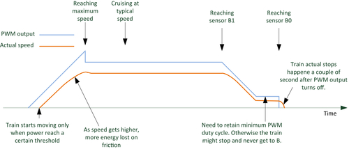
To make the problem slightly more challenging, we also need to consider the acceleration and deceleration of the train. For example, when travel from A to B, the train should accelerate to a certain speed, then cruise at a slightly lower speed, and then decelerate as it gets to sensor B1, and stop when it gets to sensor B0, as shown in Figure 18.10.
In order to tackle this application challenge, we need to decide what are needed inside the hardware and software. For the hardware, I built a simple microcontroller board (Figure 18.11) with an NXP LPC1114 microcontroller connected to four infrared obstacle detector modules that are placed under the railway track. These infrared obstacle detector modules (bottom of Figure 18.11) can be brought online at fairly low cost.

Depending on the wiring connection, a certain Pulse-width modulation (PWM) output could be driving the train from A to B or from B to A. Since it is difficult to tell during the program development (unless it is tested first), a simple direction detection step is added to the application code. This works by assuming that the train is placed in the middle of the track (between sensor A1 and B1) at the start of program execution, then applies the track with a low duty ratio PWM output to get the train moving until it reaches one of the sensors.

Figure 18.11 Microcontroller board connected to PWM module (left) and power supply module (right), and an infrared module at the bottom.
To get the speed control working as in Figure 18.10, we need to use a timer interrupt for acceleration and deceleration control. Inside the timer ISR, the inputs (sensors and the button) are sampled, and then a Finite State Machine (FSM) is implemented to handle the control sequences. The FSM has 10 states: eight states for normal operations to get the train running between A and B, and two more states for handling of user stopping request (when the push button is pressed).
The state of the FSM is held in a global variable so that the FSM code does not need to be executing all the time. The FSM processing is done inside the timer interrupt handler using a switch statement, where the new state and the new speed for the train are determined.
The FSM state diagram of the program looks slightly complex (Figure 18.12). Assume normal operations without the user pushing the press button, the state transitions are quite simple, as shown by the blue arrows. The state transitions with green arrows happens only if the user pushed the press button, and the brown arrows with dashed lines are added in case the sensor event A1/B1 are missed.
Timer is programmed to trigger at 20 Hz. Each time the timer ISR is executed, the inputs are sampled. Input events are recognized only if it is active in two successive samples and previous state of the input was inactive. Then the FSM code is executed, the PWM duty cycle is updated and return to the thread (Figure 18.13).


Compare to the program flow used in another train controller project in Chapter 17, this FSM approach is more flexible as this allows you to create multiple state-transition paths easily. In addition, the interrupt-driven application approaches the low power capability of the microcontroller to be utilized.
To help debugging, a number of printf functions are added so that we can see what the microcontroller is doing at different times. The printf messages are directed to UART (retargeting). For example, when a state transition takes place, the new state information is output to the UART.
Alternatively, the thread idle loop could put the processor into sleep mode as there is nothing else needs to be done inside thread mode after the FSM has been started.
The example code based on Keil® MDK-ARM is available on the book companion Web site.
18.6. Different Versions of CMSIS-CORE
The CMSIS project is in continuous development. The CMSIS-CORE supports the Cortex®-M0 processor starting from version 1.1, and Cortex-M0+ processor from version 3.01. The current release is version 4.3. The examples used in this book should work with most recent releases of the CMSIS-CORE.
Most of the changes of the CMSIS-CORE since version 1.3 are focus on the following:
• New processor supports
• New tool chain supports
• Directory structure changes
• Intrinsic function enhancements
• CMSIS-DSP library enhancements
The details of the changes are documented in an HTML file in the CMSIS-CORE package, for example: CMSIS_<version>∖CMSIS∖Documentation∖Core∖html∖index.html
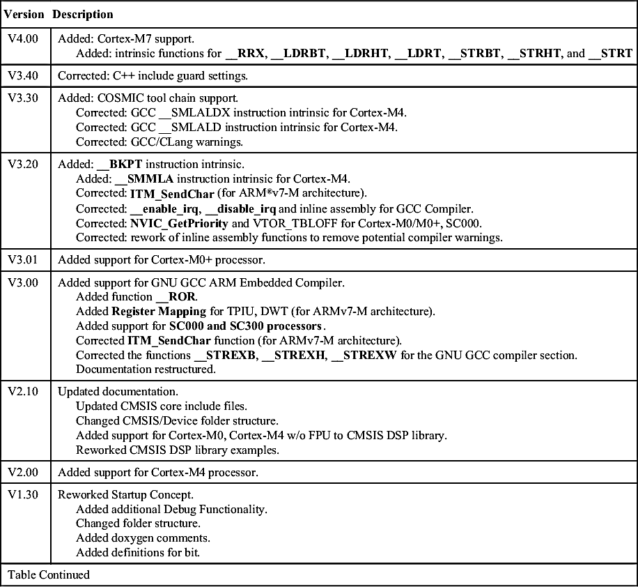
| Version | Description |
| V4.00 | Added: Cortex-M7 support. Added: intrinsic functions for __RRX, __LDRBT, __LDRHT, __LDRT, __STRBT, __STRHT, and __STRT |
| V3.40 | Corrected: C++ include guard settings. |
| V3.30 | Added: COSMIC tool chain support. Corrected: GCC __SMLALDX instruction intrinsic for Cortex-M4. Corrected: GCC __SMLALD instruction intrinsic for Cortex-M4. Corrected: GCC/CLang warnings. |
| V3.20 | Added: __BKPT instruction intrinsic. Added: __SMMLA instruction intrinsic for Cortex-M4. Corrected: ITM_SendChar (for ARM®v7-M architecture). Corrected: __enable_irq, __disable_irq and inline assembly for GCC Compiler. Corrected: NVIC_GetPriority and VTOR_TBLOFF for Cortex-M0/M0+, SC000. Corrected: rework of inline assembly functions to remove potential compiler warnings. |
| V3.01 | Added support for Cortex-M0+ processor. |
| V3.00 | Added support for GNU GCC ARM Embedded Compiler. Added function __ROR. Added Register Mapping for TPIU, DWT (for ARMv7-M architecture). Added support for SC000 and SC300 processors. Corrected ITM_SendChar function (for ARMv7-M architecture). Corrected the functions __STREXB, __STREXH, __STREXW for the GNU GCC compiler section. Documentation restructured. |
| V2.10 | Updated documentation. Updated CMSIS core include files. Changed CMSIS/Device folder structure. Added support for Cortex-M0, Cortex-M4 w/o FPU to CMSIS DSP library. Reworked CMSIS DSP library examples. |
| V2.00 | Added support for Cortex-M4 processor. |
| V1.30 | Reworked Startup Concept. Added additional Debug Functionality. Changed folder structure. Added doxygen comments. Added definitions for bit. |
| Table Continued | |
| Version | Description |
| V1.01 | Added support for Cortex-M0 processor. |
| V1.01 | Added intrinsic functions for __LDREXB, __LDREXH, __LDREXW, __STREXB, __STREXH, __STREXW, and __CLREX (for ARMv7-M architecture) |
| V1.00 | Initial Release for Cortex-M3 processor. |

Unless you are using some fairly old versions device driver libraries based in old versions of CMSIS-CORE, otherwise it is unlikely to encounter any compatibility issues.
If you are using version 1.x of CMSIS-CORE, there are several differences between the CMSIS version 1.2 and version 1.3 which apply to use CMSIS on Cortex-M0:
• SystemInit() function—In CMSIS v1.2, the SystemInit() function is called at the start of the main code. In CMSIS v1.3, the SystemInit() function could be called from the reset handler.
• “SystemCoreClock” variable is added—the “SystemCoreClock” variable is used instead of “SystemFrequency”. The “SystemCoreClock” definition is clearer—processor clock speed—while “SystemFrequency” could be unclear because many microcontrollers have multiple clocks for different parts of the system.
• Core register bit definition is added.
If you are moving software project between CMSIS-CORE version 2.0 (or older) and newer versions, you would also notice that in version 2.0 or older versions, there is a “core_cm0.c”, whereas in newer versions, all the processor core HAL (Hardware Abstraction Layer) functions are handled by header files (.h) and therefore the file “core_cm0.c” has disappeared.
In most cases, software device driver packages from microcontroller vendors should already contain the files needed. If necessary, you can download a preferred version of CMSIS on the ARM Web site (www.arm.com/cmsis).
..................Content has been hidden....................
You can't read the all page of ebook, please click here login for view all page.