This chapter covers the various areas that need attention when porting software from legacy 8-bit/16-bit architecture, as well as from ARM7TDMI™ designs, to ARM® Cortex®-M processors. It then also covers the differences between different Cortex-M processors, and the software modifications which might be required when porting software between them.
Keywords
Differences between difference Cortex®-M processors; Migration from legacy 8/16-bit architecture; Software porting between Cortex-M processors; Software porting from ARM7TDMI™
22.1. Overview
The Cortex®-M0 and Cortex-M0+ processors are designed for wide range of applications. Due to their low-power capabilities and flexible system designs, they fit very well into many applications where traditional uses of 8-bit and 16-bit microcontrollers were common. By switching to low-power 32-bit microcontroller, many designers can further enhance their products without losing out on energy efficiency or battery life.
On the other hand, many designs that are using older generations of 32-bit microcontrollers (for example, microcontrollers based on the ARM7TDMI™) or other Cortex-M processor-based microcontrollers could also benefit from switching to some of the Cortex-M0 or Cortex-M0+ microcontrollers too. For example, many Cortex-M0 and Cortex-M0+ microcontrollers are selling at very low price.
As a result, software porting is becoming a common task for some of the embedded software developers. In this chapter, we will look into the following:
• Porting of software from 8-bit and 16-bit architectures to Cortex-M0, Cortex-M0+, or Cortex-M processors in general.
• Differences between the Cortex-M0/Cortex-M0+ processors and various common ARM® processors for microcontrollers, and what areas in a program need to be modified when porting software between them.
22.2. Porting Software from 8-Bit/16-Bit Microcontrollers to ARM® Cortex®-M
22.2.1. Common Modifications
Some application developers might need to port applications from 8-bit or 16-bit microcontrollers to microcontrollers based on Cortex-M processors. By moving from these architectures to the Cortex-M0, often you can get better code density, higher performance, and lower power consumption.
When porting applications from these microcontrollers to the Cortex-M processors, the modifications of the software typically involve the following:
• Start-up code and vector table—Different processor architectures have different start-up code and interrupt vector tables and therefore these codes need to be replaced.
• Stack allocation adjustment—With ARM Cortex-M processors, the stack size requirement can be very different from an 8-bit or 16-bit architecture. In addition, the methods to define stack locations and stack sizes can also be very different from 8-bit and 16-bit development tools.
• Removal of architecture-specific/tool chain-specific C language extensions—Many of the C compilers for 8-bit and 16-bit microcontrollers require a number of C language extensions features. This included special data type like Special Function Registers (SFRs) and bit data in 8051, or various “#pragma” statements in various C compilers.
• Interrupt control—In 8-bit and 16-bit microcontroller programming, the interrupt configuration is usually done by directly writing to various interrupt control registers. When porting the applications to the ARM Cortex-M processor family, these codes should be converted to use the interrupt control functions from CMSIS-CORE for the best software portability. For example, configuration of individual interrupts can be handled by various Nested Vectored Interrupt Controller (NVIC) functions in CMSIS (e.g., NVIC_EnableIRQ and NVIC_DisableIRQ), and enable and disable of all interrupts can be converted to __enable_irq() and __disable_irq().
• Peripheral programming—In 8-bit and 16-bit microcontroller programming, the peripherals control is usually handled with programming to registers directly. When using ARM microcontrollers, many microcontroller vendors provide device driver libraries to make use of the microcontroller easier. You can use these library functions to reduce software development time, or write to the hardware registers directly if preferred. If you prefer to program the peripherals by accessing the registers directly, it is still beneficial to use the header files in the device driver library as these have all the peripheral registers defined and can save you time preparing and validating the code.
• Assembly code and inline assembly—Obviously all the assembly and inline assembly code needs to be rewritten when switching to a completely different architecture. In many cases, you can rewrite the required function in C when the application is ported to a Cortex-M processor.
• Unaligned data—Some 8-bit or 16-bit microcontrollers might support unaligned data. Since the Cortex-M0 and Cortex-M0+ processors do not support unaligned data, some data structures definitions or pointer manipulation codes might need to be changed. For data structures that require unaligned data handling, we can use the __packed attribute when defining the structure. However, the Cortex-M0 and Cortex-M0+ require multiple instructions to access an unaligned data. So it is best to convert the data structures so that all elements inside are aligned. Alternatively, if the performance of unaligned data accesses is crucial for the application, the Cortex-M3/M4/M7 processors could be more suitable as these processors support unaligned data accesses.
• Be aware of data size differences—The integers in most 8-bit and 16-bit processors are 16 bit, while in ARM architectures integers are 32 bit. This difference causes changes in overflow behavior, it can also affect memory size required for storing the data. For example, when a program file defines an array of integers from 8-bit or 16-bit architecture, we might want to change the code to use “short int” or “int16_t” (in “stdint.h”, introduced in C99) when porting the code to ARM architecture so that the size remains unchanged.
• Floating point—Many 8-bit and 16-bit microcontrollers define “double” (double precision floating point) as 32-bit data. In ARM architecture a “double” data is 64 bit. When porting applications containing floating-point operations, you might need to change the double precision floating-point data to “float” (single precision floating point). Otherwise the processing speed would be reduced and the program size could increase due to the requirement to process the data in extra precision. For the same reason, some function calls for mathematical operation might need to be changed to ensure the single precision version is used. For example, by default the cosine function “cos()” is a double precision version of the cosine function, for single precision operation, use “cosf()” instead.
• Adding fault handlers—In many 8-bit and 16-bit microcontrollers, there are no fault exceptions. While embedded applications can operate without any fault handlers, adding of fault handlers can help an embedded system to handle errors (e.g., data corruption caused by voltage drop or electromagnetic interference).
22.2.2. Memory Requirements
One of the points mentioned above is the stack size. After porting to the ARM architecture, the required stack size could increase or decrease, depending on the application. The stack size might increase because of the following:
• Each register push takes 4bytes of memory in ARM, while in 16-bit or 8-bit, each register push takes 2 bytes or 1 byte.
• In ARM programming, local variables are often stored in stack. While in some architecture local variables might be defined in a separate data memory area.
On the other hand, the stack size could decrease because of the following:
• With 8-bit or 16-bit architecture, multiple registers are required to hold a large data, and often these architectures have fewer registers compared to ARM, so more stacking would be required.
• More powerful addressing mode in ARM means address calculations can be carried out on the fly without taking up register space. The reduction of register used for an operation can reduce stacking requirement.
Overall, the total RAM size required could decrease significantly after porting because in some legacy processor architectures such as the 8051, local variables are defined statically in data memory space rather on the stack. For these architectures, the memory space is used even when the function or subroutine is not running. Whereas in ARM processors, local variables are typically allocated on stack memory and take up memory space only when the function or subroutine is executing. Also, with more registers available in the ARM processor's register bank compared to some other architectures, some of the local variables might only need to be stored in the register bank instead of taking up memory space.
Due to high code density, the program memory requirements in ARM Cortex-M processors are normally much lower than 8-bit microcontrollers, and often lower than most 16-bit microcontrollers. So when you port your applications from these 8-bit or 16-bit microcontrollers to ARM Cortex-M0 or Cortex-M0+ microcontrollers, you could possibly use a device with smaller flash memory size. The reduction of the program memory size is often caused by the following:
• Better efficiency at handling 16-bit and 32-bit data (including integers, pointers)
• More powerful addressing modes
• Some memory access instructions can handle multiple data, including PUSH and POP
There can be exceptions—For applications that contain only small amount of code, the code size in ARM Cortex-M0/Cortex-M0+ microcontrollers could be larger compared to 8-bit or 16-bit microcontrollers because of the following:
• Most of the microcontrollers based on Cortex-M processors support more interrupts and therefore have a much larger vector table (and each vector takes 4 bytes in ARM Cortex-M instead of 2 bytes in 8-bit or 16-bit microcontrollers).
• The C start-up code for ARM Cortex-M processors might be larger. Most development tool chains for ARM processor support full standard C libraries which support many features not available in 8-bit or 16-bit architecture. However, many tool chains also provide smaller version of C start-up libraries. For example, MicroLIB in ARM development tools like Keil® MDK-ARM™ or ARM DS-5™, and NewLib-Nano in ARM gcc are designed to reduce the code size.
22.2.3. Nonapplicable Optimizations for 8-Bit or 16-Bit Microcontrollers
Some optimization techniques used in 8-bit/16-bit microcontroller programming are not required on ARM processors. In some cases, these optimizations might result in extra overhead due to architecture differences. For example, many 8-bit microcontroller programmers uses character data as loop counter for array accesses:
When compiling the same program on ARM processors, the compiler will have to insert a UXTB instruction to replicate the overflow behavior of the array index (“i”). To avoid this extra overhead we should declare “i” as integer “int”, “int32_t”, or “uint32_t” for best performance.
Another example is the unnecessary use of casting. For example, the following code uses casting to avoid the generation of 16×16 multiply operation in an 8-bit processor:
Again, such casting operation will result in extra instructions in ARM architecture. Since Cortex-M processors can handle 32×32 multiply with 32-bit result in a single instruction, the program code can be simplified into:
unsignedintx,y,z; z=x∗y;
22.2.4. Example—Migrate from 8051 to ARM Cortex-M0/Cortex-M0+
In general, since most applications can be programmed in C entirely on the Cortex-M processors, the porting of applications from 8-bit/16-bit microcontrollers is usually straightforward and easy. Here we will see some simple examples of modifications required.
Vector Table
In the 8051, the vector table contains a number of JMP (jump) instructions that branch to the start of the interrupt service routines. In some development environments, the compiler might create the vector table for you automatically. For ARM Cortex-M processors, the vector table contains the address of the main stack pointer (SP) initial values, and starting addresses of the exception handlers (Table 22.1). The vector table is part of the start-up code, which is often provided by the development environment. For example, when creating new project in the Keil MDK-ARM, the software component manager (“Manage Runtime Environment”) in the project wizard can add the default start-up code into the project, which contains the vector table.
Data Type
In some cases, we need to modify the data type so as to maintain the same program behavior as shown in Table 22.2.
Some function calls might also need to be changed if we want to ensure only single precision floating point is used (Table 22.3).
Some special data types for 8051 are not available on ARM architecture: bit, sbit, sfr, sfr16, idata, xdata, bdata.
Interrupt
Interrupt control code in 8051 is normally written as direct access to SFRs. They need to be changed to CMSIS-CORE function when porting to Cortex-M microcontrollers (Table 22.4).
The interrupt service routine also requires minor modifications. Some of the special directives used by interrupt service routines specific to 8051 need to be removed when the application code is ported to the Cortex-M microcontrollers. For Cortex-M0/Cortex-M0+ processors, the interrupt service routine can be a normal C function. In ARM tool chains we can add “__irq” directive for clarify purpose (Table 22.5).
Entering of sleep mode is different too. In 8051 sleep mode can be entered by setting the IDL (idle) bit in PCON. In Cortex-M processors, you can use the WFI/WFE instructions, or use vendor-specific functions provided in the device driver library (Table 22.6).
Table 22.6
Sleep mode control change during software porting
8051
Cortex®-M0/Cortex-M0+
PCON=PCON|1;/∗EnterIdlemode∗/
__WFI();/∗Entersleepmode∗/
22.3. Differences between ARM7TDMI™ and Cortex®-M0/M0+ Processor
22.3.1. Overview of Classic ARM® Processors
Before the ARM Cortex-M processors are developed, there are a number of previous generation ARM processors being used in microcontroller applications (Table 22.7). For example, some of the ARM-based microcontrollers on the market are based on the ARM7TDMI processor, a processor that was released around 1994 and is still being used today.
While it is less common to find ARM920T, 922T, and 940T processors today, there are still ranges of ARM926EJ-S and even ARM11 series processors on the market. However, those designs are usually focussed on running embedded Linux systems and have quite different application areas compared to the Cortex-M0 and Cortex-M0+ processors. For these applications, it is more common to migrate to the newer Cortex-A processors.
Since there are still a number of ARM7TDMI-based microcontrollers on the market, we will cover the key differences between the ARM7TDMI and the Cortex-M0 and Cortex-M0+ processors, and then cover the software migration considerations.
Table 22.7
Some of the classic ARM® processors that are used in microcontroller applications
Processor
Descriptions
ARM7TDMI™
A very popular 32-bit processor and widely supported by development tools. It is based on ARM architecture version 4T and supports both ARM and Thumb instruction set. Upward compatible to ARM9, ARM11, and Cortex®-A/R processors.
ARM920T/922T/940T
Microcontrollers based on these processors are less common nowadays. They are based on ARM architecture version 4T but with Harvard bus architecture. Some of them also support cache, MMU, or MPU features.
ARM9E processor family
Most of the ARM9 microcontrollers are based on the ARM9E processor family. They are based on ARM architecture version 5TE (with Enhanced DSP instructions) and provide various memory/system features (cache, TCM, MMU, MPU, DMA, etc) depending on processor model. Usually they are targeted at higher end of microcontroller application space with high operating frequency, larger memory system support.
ARM11 processor family
They are application processors based on ARM architecture version v6 (do not confuse it with ARMv6-M). These processors are targeted at applications that require full feature OS, so they support MMU and the pipeline design is optimized for higher clock frequency. Today, ARM11 processors are still used in a range of popular projects such as the Raspberry Pi (model A, B, and B+).
22.3.2. Operation Mode
The ARM7TDMI processor has a number of operation modes, while the Cortex-M0/Cortex-M0+ processors only have two modes (Table 22.8).
Some of the exception models from the ARM7TDMI are combined in Handler mode in the Cortex-M0/Cortex-M0+ processors with different exception types. For example, see Table 22.9.
The reduction of operation modes simplifies the programs running on Cortex-M processors. For example, in ARM7TDMI you need to set up different SPs for different modes, whereas in the Cortex-M processor it is fine to run many applications with just one SP, and need a second SP when an Embedded OS is used.
Table 22.8
Operation modes comparison between ARM7TDMI™ and Cortex®-M0/Cortex-M0+ processors
Operation modes in ARM7TDMI
Operation modes in Cortex-M0
System Supervisor IRQ (interrupt) FIQ (fast interrupt) Undefined (Undef) Abort User
Thread Handler
Table 22.9
Exception comparison between ARM7TDMI™ and Cortex®-M0/Cortex-M0+ processor
Exceptions in ARM7TDMI
Exception in Cortex-M0
IRQ FIQ Undefined (Undef) Abort Supervisor
Interrupts Interrupts HardFault HardFault SVCall
22.3.3. Registers
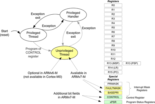
The ARM7TDMI has a register bank with banked registers based on current operation mode. In the Cortex-M0 or Cortex-M0+ processor, only the SP is banked. And in most simple applications without an OS, only the Main Stack Pointer (MSP) is required. Figure 22.1 shows the comparison of the register bank between ARM7TDMI and Cortex-M0/M0+ processors.
Figure 22.1 Register bank differences between ARM7TDMI™ and the Cortex®-M0/Cortex-M0+ processors.
There are some differences between the CPSR (Current Program Status Register) in the ARM7TDMI and the xPSR in the Cortex-M processors. For instance, the mode bits in CPSR are removed, replaced by IPSR, and interrupt masking bit I-bit is replaced by the PRIMASK register, which is separated from the xPSR.
Despite the differences between the register banks, the programmer's model or R0 to R15 remains the same. As a result, most Thumb® instruction codes on ARM7TDMI can be reused on Cortex-M processors, simplifying software porting.
22.3.4. Instruction Set
The ARM7TDMI supports the ARM instructions (32 bit) and Thumb instructions (16 bit) in ARM architecture v4T. The Cortex-M0 and Cortex-M0+ processors support Thumb instructions in ARMv6-M, which is a superset of the Thumb instructions supported by the ARM7TDMI. However, the Cortex-M processors do not support ARM instructions. Therefore applications for ARM7TDMI must be modified when porting to Cortex-M microcontrollers.
22.3.5. Interrupts
The ARM7TDMI supports an IRQ interrupt input and an FIQ (Fast Interrupt) input. Normally a separate interrupt controller is required in an ARM7TDMI microcontroller to allow multiple interrupt sources to share the IRQ and FIQ inputs. As a result, the interrupt control codes need to be modified.
In ARM7TDMI, since the FIQ has more banked registers and its vector is located at the end of the vector table, it can work faster by reducing the register stacking required and the FIQ handler can be placed at the end of vector table to avoid branch penalty.
Unlike the ARM7TDMI, the Cortex-M0 and Cortex-M0+ processors have a built-in interrupt controller called NVIC with up to 32 interrupt inputs. Each interrupt can be programmed at one of the four available priority levels. There is no need to separate interrupts into IRQ and FIQ because stacking of registers is handled automatically by hardware. In addition, the vector table in Cortex-M processors stores the starting address of each interrupt service routine, while in ARM7TDMI the vector table holds instructions (usually branch instructions that branch to interrupt service routines).
When the ARM7TDMI processor receives an interrupt request, the interrupt service routine starts in ARM state (using ARM instruction set). Additional assembly wrapper code is also required to support nested interrupts. In Cortex-M processors there is no need to use assembly wrappers for normal interrupt processing.
22.4. Porting Software from ARM7TDMI™ to the Cortex®-M0/Cortex-M0+ Processors
Application codes for ARM7TDMI must be modified and recompiled to be used on the Cortex-M0/Cortex-M0+ processors.
22.4.1. Start-up Code and Vector Table
Since the vector table and the initialization sequence are different between ARM7TDMI and the Cortex-M0 or Cortex-M0+ processor, the start-up code and the vector table must be replaced (See Table 22.10).
Examples of start-up code for Cortex-M0/Cortex-M0+ based microcontrollers can be found in various examples in this book, which is available on the companion Web site.
22.4.2. Interrupt
Since the interrupt controller used in microcontrollers with ARM7TDMI would be different from the NVIC in the Cortex-M0 or Cortex-M0+ processor, all the interrupt control codes need to be updated. It is recommended to use NVIC access functions defined in CMSIS-CORE for portability.
The interrupt wrapper functions for nested interrupt support for the ARM7TDMI processor must be removed. If the interrupt service routine was written in assembly, the handler code will probably require rewriting because many ARM® instructions cannot be directly mapped to Thumb® instructions. For example, the exception handler in ARM7TDMI can be terminated by “MOVS PC, LR” (ARM instruction). This is not valid for Cortex-M0/M0+ processors and must be replaced by a “BX LR” instruction or a POP instruction.
Table 22.10
Vector table differences between ARM7TDMI™ and Cortex®-M0/Cortex-M0+ processors
Vector table in Arm7TDMI
Vector table in the Cortex-M0/Cortex-M0+
Vectors BReset_Handler BUndef_Handler BSWI_Handler BPrefetchAbort_Handler BDataAbort_Handler BIRQ_Handler BFIQ_Handler Reset_Handler; Setup Stack for each mode LDRR0,=Stack_Top MSRCPSR_c, #Mode_IRQ:OR:I_Bit:OR:F_Bit MOVSP, R0 …; setup stack for other modes IMPORT__main LDRR0, = __main; Enter C startup BXR0
Vectors IMPORT__main DCD_stack_top; Main SP starting value DCD__main; Enter C startup DCDNMI_Handler DCDHardFault_Handler DCD0,0,0,0,0,0,0 DCDSVC_Handler DCD0, 0 DCDPendSV_Handler DCDSysTick_Handler …; vectors for other interrupt handlers
FIQ handlers for the ARM7TDMI processor might rely on the behavior that R8 to R14 are banked in ARM7TDMI to save execution time. For example, constants used by the FIQ handler might be preloaded into these banked registers before the FIQ is enabled. When porting such handlers to the Cortex-M processors, the constants must be loaded into the registers within the handler.
In some cases you might find assembly code being used to enable or disable interrupts by modifying the I-bit in CPSR. In Cortex-M processor, this is replaced by the PRIMASK interrupt masking register. Note that in ARM7TDMI, you can carry out the exception return and change I-bit in a single exception return instruction. In the Cortex-M processors, this method cannot be used because the PRIMASK and xPSR are separate registers. As a result, if the PRIMASK register is set during an exception handler, it must be cleared before the exception exit. Otherwise the PRIMASK register will remain set and no other interrupts (apart from NMI) can be accepted.
22.4.3. C Program Code
Apart from the usual changes due to peripherals, memory map, and system level feature differences, the C applications might require changes in the following areas:
• Compile directives like “#pragma arm” and “#pragma thumb” are no longer required because the Cortex-M processors support Thumb instructions only.
• For project previously created with ARM RealView Development Suite (RVDS), DS-5™ or Keil® MDK tool chains, it is likely that all inline assembly codes have to be rewritten because the inline assembly in the ARM tool chain previously only supports ARM instructions, which is not supported in the Cortex-M processors. To rewrite these inline assembly codes, this could be done either using inline assembly, embedded assembler, separate assembly code, or C functions. Users of GNU C compiler might also need to modify their inline assembly code if that was written for ARM instructions, or if the code attempts to switch to ARM state.
• Exception handlers can be simplified because in the Cortex-M processors, each interrupt has its own interrupt vector. There is no need to use software to determine which interrupt service is required and there is no software overhead in supporting nested interrupts.
• Although the “__irq” directive is not essential in the exception handlers for Cortex-M processors, this directive for interrupt handlers can be retained in the ARM DS-5 or Keil MDK-ARM™ projects for clarity. It might also help software porting if the application has to be ported to other ARM processors in the future.
The C code should be recompiled to ensure that only Thumb instructions are used and no attempt to switch to ARM state should be contained in the compiled code. Similarly, library files must also be updated to ensure that it will work with Cortex-M processors.
22.4.4. Assembly Code
Due to the fact that the Cortex-M processors do not support the ARM instruction set, assembly code which uses ARM instructions has to be rewritten.
Be careful with legacy Thumb programs that use the CODE16 directive. When the CODE16 directive is used, the instructions are interpreted as traditional Thumb syntax. For example, data processing op-codes without S suffixes are converted to instructions that update APSR when CODE16 directive is used. However, you can reuse assembly files with CODE16 directive because it is still supported by existing ARM development tools. For new assembly code, the Thumb directive is recommended, which indicates to the assembly that the UAL (Unified Assembly Language) is used. With UAL syntax, data processing instructions updating the APSR require the S suffix.
Fault handlers and system exception handlers like SWI must also be updated to work with Cortex-M processors.
22.4.5. Atomic Access
Since Thumb instructions do not support swap (SWP and SWPB instructions), code for handling atomic access must be changed. For single processor systems without other bus master, you can use either the exception mechanism or PRIMASK interrupt masking register to achieve atomic operations. For example, you can use SVCall exception as a gateway to handle atomic operations because there can only be one instance of the SVCall exception handler running (when an exception handler is running, other exceptions of same or lower priority levels are blocked).
22.4.6. Optimizations
After getting the software working on the Cortex-M0 or Cortex-M0+ processor, there are various areas you can look into to optimize your application code.
For assembly code migrated from the ARM7TDMI, the data type conversion is one of the potential areas for improvement due to new instructions available in the ARMv6-M architecture.
If the interrupt handlers were written in assembly, there might be chance that the stacking operations can be reduced since R0–R3, R12 are automatically stacked by the exception sequence.
More sleep mode features are available in the Cortex-M processors which can be used to reduce power consumption. To take the full advantages of the low power features on a Cortex-M0 or Cortex-M0+ based microcontroller, you will need to modify your application codes to make use of the power management features in the microcontroller. These features are dependent on the microcontroller products and the information in this area can usually be found in user manuals or application notes provided by the microcontroller vendors. Chapter 19 covers some of the examples of using low power features in microcontrollers.
With the nested interrupts being automatically handled by processor hardware and availability of programmable priority levels in the NVIC, priority level of the exceptions can be rearranged for best system performance.
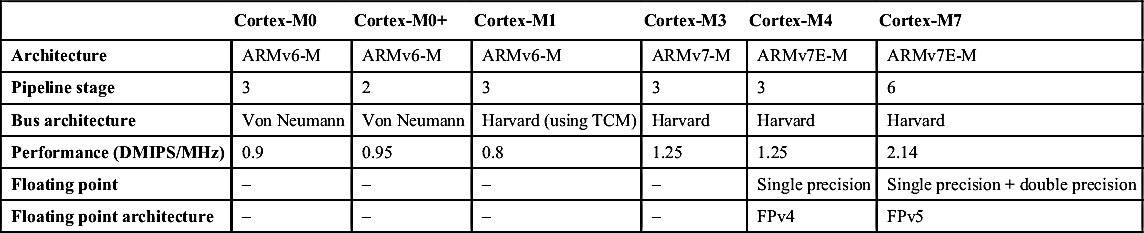
22.5. Differences between Various Cortex®-M Processors
High-level architecture comparison of the Cortex®-M processors
Cortex-M0
Cortex-M0+
Cortex-M1
Cortex-M3
Cortex-M4
Cortex-M7
Architecture
ARMv6-M
ARMv6-M
ARMv6-M
ARMv7-M
ARMv7E-M
ARMv7E-M
Pipeline stage
3
2
3
3
3
6
Bus architecture
Von Neumann
Von Neumann
Harvard (using TCM)
Harvard
Harvard
Harvard
Performance (DMIPS/MHz)
0.9
0.95
0.8
1.25
1.25
2.14
Floating point
–
–
–
–
Single precision
Single precision + double precision
Floating point architecture
–
–
–
–
FPv4
FPv5
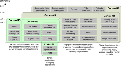
In terms of system level aspects, the main differences among the Cortex-M processors are shown in Figure 22.2.
The Cortex-M3, Cortex-M4, and Cortex-M7 processors have higher performance than the Cortex-M0 and Cortex-M0+ processors due to extra instructions, various differences in the bus level architecture and processor's pipeline (e.g., superscalar support in the Cortex-M7 processor). However, the additional capabilities also increase power consumption. So it is important to understand the requirements of the targeted applications (e.g., battery life vs performance) and the characteristics of the microcontroller products when selecting the processor for your projects.
Figure 22.2 The Cortex®-M processor family.
22.5.2. Programmer's Model
The ARMv7-M architecture (including ARMv7E-M) is a superset of the ARMv6-M architecture. So processors based on ARMv7-M architecture provide all the architectural features available in the ARMv6-M. In addition to that, the Cortex-M3, Cortex-M4, and Cortex-M7 processors provide various additional features.
For the programmer's model, unprivileged mode (Unprivileged Thread—when not executing exception handlers) is optional in ARMv6-M and is not available in the Cortex-M0 processor at all. This is always available in ARMv7-M architecture. The unprivileged thread mode has limited access to the processor configuration registers (e.g., NVIC, SysTick), and an optional memory Protection Unit (MPU) can be used to block programs running in user threads from accessing certain memory regions (Figure 22.3).
Apart from the operation modes being different, the ARMv7-M architecture also has additional interrupt masking registers. The BASEPRI register allows interrupts of certain priority level or lower to be blocked, and the FAULTMASK provides additional fault management features.
Figure 22.3 Programmer's model differences between ARMv6-M and ARMv7-M architectures.
The control register in the Cortex-M4 and Cortex-M7 processors also has an additional bit (bit[2]—Floating Point Context Active, FPCA) to indicate if current executing context has been using floating point operations.
The xPSR in the ARMv7-M architecture also has a number of additional bits to allow an interrupted multiple load/store instruction to be resumed from the interrupted transfer, and to allow an instruction sequence (up to four instructions) to be conditionally executed. And when DSP extension is present (i.e., Cortex-M4 and Cortex-M7 processors), there are also additional bit field (GE[3:0]—Great Than or Equal flags) for some of the SIMD (Single Instruction Multiple Data) operations.
Finally, the ARMv7-M architecture supports unaligned data transfers for a limited range of load and store instructions, while ARMv6-M architecture does not.
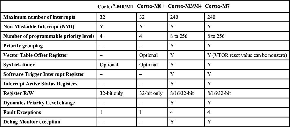
22.5.3. NVIC and Exceptions
The NVIC in the Cortex-M3, Cortex-M4, and Cortex-M7 processors supports up to 240 interrupts. The number of priority levels is also configurable by the chip designers, from 8 levels to 256 levels (in most cases 8 levels to 32 levels). The priority level settings can also be optionally configured into preemption priority (for nested interrupt) and subpriority (use when multiple interrupts of same preempt priority happening at the same time) by software.
The differences of the NVIC features in the Cortex-M processors are shown in Table 22.12.
Table 22.12
NVIC features comparison
Cortex®-M0/M1
Cortex-M0+
Cortex-M3/M4
Cortex-M7
Maximum number of interrupts
32
32
240
240
Non-Maskable Interrupt (NMI)
Y
Y
Y
Y
Number of programmable priority levels
4
4
8 to 256
8 to 256
Priority grouping
–
–
Y
Y
Vector Table Offset Register
–
Optional
Y
Y (VTOR reset value can be nonzero)
SysTick timer
Optional
Optional
Y
Y
Software Trigger Interrupt Register
–
–
Y
Y
Interrupt Active Status Registers
–
–
Y
Y
Register R/W
32-bit only
32-bit only
8/16/32-bit
8/16/32-bit
Dynamics Priority Level change
–
–
Y
Y
Fault Exceptions
1
1
4
4
Debug Monitor exception
–
–
Y
Y
There are a number of differences, but in terms of software porting across different Cortex-M processors it is often quite straightforward, as shown in Table 22.13. One of the major differences is that some of the NVIC registers in ARMv7-M can be accessed using byte or half-word accesses, whereas in ARMv6-M it is limited to 32-bit accesses. For example, if an interrupt priority register needs to be updated, you need to read the whole word (which consists of priority level settings for four interrupts), modify 1byte, and then write it back. In ARMv7-M architecture, this can be carried out using just a single-byte size write to the priority level register. For users of the CMSIS device driver library, this difference in the programmer's model does not cause any software porting issue because NVIC access functions in CMSIS-CORE have the same name and the function implementations for each processor use the correct access method for ARMv6-M or ARMv7-M accordingly.
Table 22.13
Handling of NVIC feature differences
Key Differences
Software changes
Software Trigger Interrupt Register not available in ARMv6-M
In Cortex®-M0/Cortex-M0+ processors, use Interrupt Set Pending Register (ISPR) instead (supported by CMSIS-CORE NVIC_SetPending(IRQn_tIRQn))
Different register access size requirements
Use CMSIS-CORE NVIC control functions instead
Dynamic priority level change
Disable IRQ temporarily when changing priority level
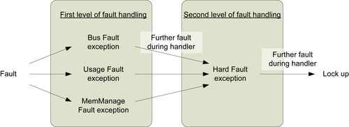
Cortex-M processors with ARMv7-M architecture have additional fault handlers with programmable priority level. It allows the embedded systems to be protected by two levels of fault exception handlers (Figure 22.4).
Figure 22.4 Multiple levels of fault handling in ARMv7-M architecture.
These additional fault handlers are programmable. By default they are disabled (and the fault exception would trigger HardFault exception instead). If enabled, these additional fault handlers can be used to handle specific range of fault events as shown in Table 22.14.
There is also a Debug Monitor exception in ARMv7-M architecture. This is for software-based debug solution and is not needed for application code.
Table 22.14
Additional fault exceptions in the ARMv7-M architecture
Exception types
Usage
Bus Fault
Handling of bus error responses
Usage Fault
Handling of undefined instructions or illegal operations (e.g., attempt to switch to ARM® state which is not supported on Cortex®-M processors)
MemManage (Memory Management)
Typically for use together with the memory protection unit, robust systems can be built for embedded systems that required high reliability
22.5.4. Instruction Set
In addition to the Thumb instructions supported in the Cortex-M0 and Cortex-M0+ processors, the Cortex-M3, Cortex-M4, and Cortex-M7 processors also support a number of additional 16-bit and 32-bit Thumb® instructions. These included the following:
• Signed and unsigned divide instructions (SDIV and UDIV)
• Compare and branch if zero (CBZ), compare and branch if not zero (CBNZ)
• IF-THEN (IT) instruction—allows up to four subsequence instructions to be conditionally executed based on the status in APSR
• Multiply and accumulate instructions for 32-bit and 64-bit results
• Count leading zero (CLZ)
• Bit field processing instructions for bit order reversing, bit field insert, bit field clear, bit field extract
• Table branch instructions (commonly used for switch statement in C)
• Saturation operation instructions
• Exclusive accesses for multiprocessor environments
• Additional instructions that allow high registers (R8 and above) to be used in data processing, memory accesses, and branches.
These additional instructions allow faster processing of complex data like floating point values. They also allow the Cortex-M3, Cortex-M4, and Cortex-M7 processors to be used in audio signal processing applications, real-time control systems.
The Cortex-M4 and Cortex-M7 processors support a superset of the instructions in the Cortex-M3. The additional instructions include the following:
• A range of SIMD instructions
• Saturation arithmetic operations
• Additional DSP support instructions (various types of MAC operations)
• Optional single precision floating point unit for Cortex-M4 and Cortex-M7 processors
• Optional double precision floating point unit for Cortex-M7 processor.
When porting applications from ARMv7-M to ARMv6-M:
• C/C++ programs only need to be recompiled to ensure that instructions that are not available are not used
• The CMSIS-DSP libraries are available for all Cortex-M processors. So you can reuse the function calls to the CMSIS-DSP library. However, the processing time and memory size requirements would change.
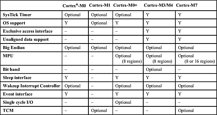
22.5.5. System Level Features
There is a range of system level features differences among the various Cortex-M processors, as shown in Table 22.15.
Table 22.15
System level features comparison
Cortex®-M0
Cortex-M1
Cortex-M0+
Cortex-M3/M4
Cortex-M7
SysTick Timer
Optional
Optional
Optional
Y
Y
OS support
Y
Optional
Y
Y
Y
Exclusive access interface
–
–
–
Y
Y
Unaligned data support
–
–
–
Y
Y
Big Endian
Optional
Optional
Optional
Optional
Optional
MPU
–
–
Optional (8 regions)
Optional (8 regions)
Optional (8 or 16 regions)
Bit band
–
–
–
Optional
–
Sleep interface
Y
–
Y
Y
Y
Wakeup Interrupt Controller
Optional
–
Optional
Optional
Optional
Event interface
Y
–
Y
Y
Y
Single cycle I/O
–
–
Optional
–
–
TCM
–
Optional
–
–
Optional
There are a number of features available on the ARMv7-M architecture that are not available on ARMv6-M architecture.
Unaligned memory accesses—In the ARMv6-M architecture, all the data transfer operations must be aligned. This means a word-size data transfer must have address a value divisible by 4, and half-word data transfer must occur at even addresses. The ARMv7-M architecture allows many memory access instructions to generate unaligned transfers. On the ARMv6-M (e.g., Cortex-M0 and Cortex-M0+ processors), access of an unaligned data has to be carried out by multiple instructions.
Exclusive accesses—The ARMv7-M architecture supports instructions for exclusive accesses, which is used for handling of shared data in multiprocessor systems such as semaphore operations. The processor bus interface supports additional signals for connecting to a system level exclusive access monitor unit on the bus system.
The Cortex-M3 and the Cortex-M4 processors have an optional system feature call bit band. This feature creates 2-bit addressable memory regions called the bit-band regions. The first bit-band region is in the first 1MB of the SRAM region (from 0x20000000), and the second one is the first 1MB of the peripheral region (0x40000000). Using two other memory address range called bit-band alias regions, each data bit in the bit-band region can be individually accessed and modified. With the Cortex-M0 and Cortex-M0+ processors, although the processors themselves do not have the bit-band feature, equivalent functionality can be added to the system using bus level mapping components. So it is possible for a Cortex-M0 or Cortex-M0+ microcontroller to provide bit-band feature as in Cortex-M3 and Cortex-M4-based designs.
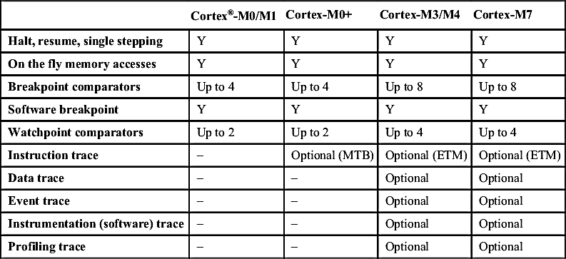
22.5.6. Debug and Trace Features
Compared to ARMv6-M architecture, the ARMv7-M architecture provides additional debug and trace capabilities. In addition, the design of the Cortex-M3 and Cortex-M4 processors allows higher number of hardware breakpoint and data watchpoint comparators, but of course the increase in debug functionalities means there is a trade off of larger silicon size and power.
A comparison of the debug and trace features is show in Table 22.16.
Table 22.16
Debug and trace features comparison
Cortex®-M0/M1
Cortex-M0+
Cortex-M3/M4
Cortex-M7
Halt, resume, single stepping
Y
Y
Y
Y
On the fly memory accesses
Y
Y
Y
Y
Breakpoint comparators
Up to 4
Up to 4
Up to 8
Up to 8
Software breakpoint
Y
Y
Y
Y
Watchpoint comparators
Up to 2
Up to 2
Up to 4
Up to 4
Instruction trace
–
Optional (MTB)
Optional (ETM)
Optional (ETM)
Data trace
–
–
Optional
Optional
Event trace
–
–
Optional
Optional
Instrumentation (software) trace
–
–
Optional
Optional
Profiling trace
–
–
Optional
Optional
The Cortex-M3, Cortex-M4, and Cortex-M7 processors support trace connection, which allows a range of addition information to be sent to the debugger in real time to provide more information about the program execution:
• The optional ETM (Embedded Trace Macrocell) allows information about instruction execution to be captured so that the instruction execution sequence can be reconstructed on debugging hosts.
• The optional DWT (Data Watchpoint and Trace) unit can be used to generate trace for watched data variables or access to memory ranges. The DWT can also be used to generate event trace, which shows information of exception entrance and exit, and profiling trace that provides statistical information about the program execution.
• The optional ITM (Instrumentation Trace Macrocell) can be used by software to generate debug messages (e.g., printf) so that you do not need to use a device-specific UART for debug messages. This enables easier debug message generation: no need to set up the UART and I/O pins, which requires device-specific setup code, and do not require a separate connection as the trace interface supports multiple trace sources.
The trace data can be captured using a trace capturing device such as the Keil® ULINKPro™.
In addition to debug and trace, the breakpoint unit in the Cortex-M3 and Cortex-M4 processors can also be used for patching code in ROM (e.g., mask ROM). This feature is called flash patch. For microcontroller devices based on flash memories this feature is not required as the program code can be updated by reprogramming the flash.
22.6. General Software Modifications when Porting between Cortex®-M Processors
Typically porting an application from one Cortex-M microcontroller to another involves quite a few modifications:
• Replacing of device driver libraries and device-specific header files
• Replace device-specific start-up code
• Interrupt priority level changes (for example, when moving from a Cortex-M3 microcontroller device to a Cortex-M0 device, some of the priority levels are not available)
• Peripheral driver code changes—unless CMSIS-Driver was used and is available for both devices
• Program code changes due to differences in device's system features (e.g., PLL, clock management, memory map)
• Compilation option changes (e.g., processor type options, floating-point options)
• Replace the embedded OS to a suitable version. Embedded OS typically contains small parts of codes that are written in assembly (e.g., context switching) and therefore needs different versions when switching between ARMv6-M and ARMv7-M.
22.7. Porting Software between Cortex®-M0/M0+ and Cortex-M1
In general, software porting between Cortex-M0 and Cortex-M1 processors is extremely easy. Apart from peripheral programming model differences, there are very few required changes.
Since both processors are based on the same instruction set, and the architecture version is the same, the same software code can often be used directly when porting from one processor to another. The only exception is when the software code uses sleep features. Since the Cortex-M1 processor does not support sleep modes, application codes using WFI and WFE would need to be updated.
There is also a small chance that the software needs minor adjustment due to execution timing differences.
At the time of writing, there is no CMSIS software package available for the Cortex-M1 processor. However, you can use the same CMSIS-CORE header files for Cortex-M0 on Cortex-M1 devices because they have almost the same architectural features.
22.8. Porting Software between Cortex®-M0/M0+ and Cortex-M3
Although there are a number of differences between Cortex-M0/M0+ processor (ARMv6-M) and the Cortex-M3 processor (ARMv7-M), porting software between the two processors is usually very easy. Since the ARMv7-M supports all features in the ARMv6-M, applications developed for Cortex-M0/Cortex-M0+ can work on a Cortex-M3 microcontroller directly, apart from changes due to memory map, execution timing, and peripheral differences (Figure 22.5).
Normally, when porting an application from Cortex-M0 to Cortex-M3 processor, you only need to change the device driver library, change the peripheral access code, and update the software for system features like clock speed, sleep modes, etc. For best performance, the code should be recompiled to make the most of the richer instruction set.
Porting software from Cortex-M3 to Cortex-M0 or Cortex-M0+ processor might require a bit more effort. Apart from switching the device driver library and recompiling the code, you also need to consider the following areas:
• NVIC and SCB (System Control Block) registers in the ARMv6-M can only be accessed in word-size transfers. If any program code accesses these registers in byte-size transfers or half-word transfers, they need to be modified. If the NVIC and SCB are accessed by using CMSIS functions, switching the CMSIS compliant device driver to use Cortex-M0 or Cortex-M0+ processor should automatically handle these differences.
• Some exception priority levels in an application for Cortex-M3 processor are not available on the Cortex-M0/Cortex-M0+ processors. So the priority level configuration might need to be changed.
• Exception priority grouping feature is not available in ARMv6-M. In ARMv7-M architecture, exception priority level registers can be partitioned into group priority and subpriority parts, with preemption based on group priority.
Figure 22.5 Compatibility between the Cortex®-M0/M0+ processor and the Cortex-M3 processor.
• Some registers in the NVIC and the SCB in the Cortex-M3 processor are not available in the Cortex-M0 or Cortex-M0+ processor. These included Interrupt Active Status Register, Software Trigger Interrupt Register, and some of the fault status registers. The Vector Table Offset Register (VTOR) is optional on the Cortex-M0+ processor, but is not available on the Cortex-M0 processor.
• The CMSIS-CORE functions listed in Table 22.17 are available for ARMv7-M processors (including Cortex-M3, Cortex-M4, and Cortex-M7) and are not available for Cortex-M0 and Cortex-M0+ processors.
• The bit-band feature in the Cortex-M3 and Cortex-M4 processors is not available in Cortex-M0 and Cortex-M0+ processors. If the bit-band alias accesses are used in the application, and if the system design of the microcontroller does not offer any system level bit band wrapper, the code needs to be converted to use normal memory accesses and handle bit extract or bit modification by software.
• If the application contains assembly code or embedded assembly code, the assembly code would likely to require modifications because many of the instructions on the Cortex-M3 processor are not available on ARMv6-M.
• For C application code, some instructions such as hardware divide are not available in the Cortex-M0 and Cortex-M0+ processors. In this case the compiler will automatically call the C library to handle the divide operation.
• Unaligned data transfer is not available in the ARMv6-M architecture.
• Some instructions available in Cortex-M3 (e.g., exclusive accesses, bit field processing) are not available in the ARMv6-M architecture.
Some Cortex-M0 and Cortex-M0+ processor microcontrollers support a memory remapping feature in order to allow the system to boot up with a boot loader with a different vector table, or allow part of the SRAM to be used as vector table so that exception vectors can be modified at runtime. This is a device-specific feature, and is more likely to be found in the Cortex-M0-based microcontroller products because the Cortex-M0 processor does not have VTOR. When migrating applications that use vector table relocation feature on Cortex-M3 processor, it might be possible to use the device-specific memory remapping feature for the same purpose.
Table 22.17
CMSIS-CORE interrupt functions in ARMv7-M that are not available in ARMv6-M
CMSIS-CORE interrupt functions for Cortex®-M3/M4/M7 not available for Cortex-M0/M0+
Applications that require the unprivileged thread mode or the MPU feature cannot be ported to the Cortex-M0 processor because these features are not supported in the Cortex-M0 processor. However, you could use a Cortex-M0+ microcontroller device for such scenario.
Please note that some of the MPU control code might also need to be changed when moving from ARMv7-M to ARMv6-M because of some small differences in the programmer's model. Please refer to Section 12.9 in Chapter 12 for more information.
22.9. Porting Software between Cortex®-M0/M0+ and the Cortex-M4/M7 Processor
Similar to Cortex-M3, the Cortex-M4 and Cortex-M7 processors are also based on the ARMv7-M architecture. The Cortex-M4 processor is very similar to the Cortex-M3 in many aspects: it has the same Harvard bus architecture, same system level features, same exception types, and has approximately the same performance in term of Dhrystone DMIPS/MHz, etc. The Cortex-M7 processor is a much more complex design with a longer 6-stage processor pipeline, superscalar processing capability, and more memory system features.
In terms of the instruction set, the Cortex-M4 and Cortex-M7 processors have additional instructions compared to the Cortex-M3 such as:
• SIMD instructions,
• saturation arithmetic instructions,
• data packing and extraction instructions, and
• optional floating-point instructions.
The floating-point support in the Cortex-M4 and Cortex-M7 processors is optional; therefore not all Cortex-M4/M7 microcontrollers will support this feature. If the floating-point unit is included, it includes an additional floating-point register bank and additional registers, as well as extra bit fields in the control special register (Figure 22.6). The floating-point unit can be turned on/off by software to reduce power consumption. The xPSR special register in Cortex-M4 and Cortex-M7 processors also has additional bit fields (GE flags) for the SIMD instructions.
Since there is no floating-point unit in Cortex-M0 and Cortex-M0+ processors, if the application code contains floating-point calculation, the calculation needs to be handled by runtime software libraries and therefore can take a lot longer and require additional code space. However, apart from that the code can just be recompiled and executed on the Cortex-M0 and Cortex-M0+ processors without any issue.
Some of the application codes designed for Cortex-M4 and Cortex-M7 processors make use of the SIMD instructions and high DSP performance of these processors. Typically the DSP functions could have been implemented with precompiled DSP library code, or handcrafted assembly code for best optimization. These codes cannot be used on the Cortex-M0 or Cortex-M0+ processor, and the operations have to be rewritten in C/C++ and recompiled. Although it is possible to get it to work, the performance of running these applications on Cortex-M0 or Cortex-M0+ processor would be much slower and therefore some of the more demanding applications (e.g., real-time audio processing, or control applications that require floating-point operations) are unsuitable for the Cortex-M0 and Cortex-M0+ processors.
Figure 22.6 Programmer's model of Cortex®-M4/Cortex-M7 processors with floating-point unit.