
Chapter 14
Getting Started with the Keil Microcontroller Development Kit
Abstract
This chapter covers how to use the Keil® MDK-ARM to develop simple programs for a number of development boards. The topics covered include how to create and customize a project, the program compilation flow, how to use the IDE, and how to use some of the debug features such as using MTB for instruction trace.
Keywords
Keil Microcontroller Development Kit (MDK-ARM) overview; Optimization options; Project creating; Project options; Software compilation flow; Using CMSIS-CORE and CMSIS-PACK; Using MTB for instruction trace; Using the μVision® debugger14.1. Introduction to Keil Microcontroller Development Kit
14.1.1. Overview
The ARM® Keil® Microcontroller Development Kit (MDK-ARM) is one of the most popular development suites for ARM microcontrollers. The Keil MDK is a Windows-based development suite and provides the following components:
• μVision® Integrated Development Environment (IDE)
• ARM Compilation Tools including
• C/C++ compiler
• Assembler
• Linker and utilities
• Debugger
• Simulator
• RTX Real-Time OS Kernel, an embedded OS for microcontrollers
• Reference start-up code for over 3000s of microcontrollers
• Flash programming algorithms for various microcontrollers
• Program examples and development board support files
A Lite version of the Keil MDK-ARM can be downloaded from the Keil Web site (www.keil.com). The Lite version of the tool is limited to 32-KB program code (compiled size), but has no time limitation. This 32-KB memory size is sufficient for most simple applications. If you need to create more complex applications, you can purchase a license on Keil Web site and obtain a software license number. This license number can then be used to turn the evaluation version to a full version. The Lite version of Keil MDK-ARM is also included in a number of Cortex®-M evaluation kits from various microcontroller vendors. A special version of Keil MDK-ARM for STM32L0/F0 devices is also available from http://www2.keil.com/stmicroelectronics-stm32.
14.1.2. The Tools
The C compiler used in the Keil MDK is based on the same compiler engine in the ARM Compilation Tools, which is also used in the ARM Development Studio 5 (DS-5™) product. This compilation tool provides excellent performance and code density.
If needed, you can also use Keil MDK with gcc. For more information on this topic, please refer to Chapter 16.
The debugger in μVision IDE works with a number of debug adaptors:
• Keil USB-JTAG adaptors like ULINK™2 and ULINK Pro, ULINK-ME
• Signum JtagJet/JtagJet-Trace
• SEGGER J-Link, J-Trace
There are also a number of debug adaptors that come with development boards:
• CMSIS-DAP (an open source debug adaptor project in the CMSIS project)
• ST-LINK, ST-LINK V2
• Silicon Labs UDA Debugger
• Stellaris ICDI (Texas Instrument)
• NULink Debugger
It is also possible to use other debug adaptors if a third party debugger plugin is available. For example, CooCox (www.coocox.org) provides open debug probes called CoLink and CoLinkEx. The design information and schematics for these hardware probes is freely available, so that anyone can build their own debug adaptor in a “DIY” manner.
Even if you do not have an in-circuit debugger, you could generate the program image and program the microcontroller using third party programming tools. But of course, having a supported in-circuit debugger allows you to debug the system though the μVision IDE which is much easier and more effective. Many low cost development boards also have built-in debug adaptors which can also be used as stand-alone adaptors for a separate microcontroller device.
14.1.3. Advantages of Using Keil MDK
Keil MDK provides a high-quality compiler, lots of features, and wide range of microcontroller product support. It is also designed to be very easy to use.
Another advantage of using the Keil MDK is that it supports a huge number of ARM microcontrollers on the market. In addition to standard compiler and debug support, it also provides configuration files such as start-up code and RTX OS configuration files, making software development easier and quicker.
Since version 5 of the Keil MDK, the IDE supports the CMSIS-PACK feature. By using the software pack installer, you can download up to date software packages for the microcontroller device you use easily.
14.1.4. Installation
The Keil MDK can be downloaded from http://www.keil.com/arm/demo/eval/arm.htm.
After the Keil MDK is installed, you also need to download and install the software packs for the microcontroller devices. You can either use the pack installer to handle the download and installation (Figure 14.1), or download the pack from www.keil.com/pack and then install them manually inside the pack installer.
The pack installer (Figure 14.2) allows you to install up-to-date software packages for more than 3000 Cortex-M microcontroller devices. Simply click on install button on the left-hand side and the program would download and install the required software package into the tool chain automatically.
Currently Keil MDK is available only for Windows platform.
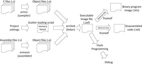
14.2. Typical Program Compilation Flow
A typical program compilation flow of a project in the Keil® MDK environment is illustrated in Figure 14.3. Once a project is created, the compilation flow can be handled by the IDE and therefore you can program your microcontroller and test it with just a few steps.
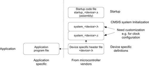
With the Cortex®-M microcontroller, although you can program almost everything in C, the start-up code for ARM® tool chains (which is provided by the microcontroller vendors and usually included in the Keil software pack installation) is usually in assembly language. In addition, you will normally need a few more files from the microcontroller vendors (as covered in Chapter 3, Section 3.5.4), which are typically also included in the software pack. As a minimum, you can create a project with just one application file and a few files from the microcontroller vendor, as shown in Figure 14.4.

Behind the scenes, the device-specific header file pulls in further CMSIS-CORE header files including some generic CMSIS-CORE files from ARM®, as shown in Figure 14.5. Typically you can include these files easily by enabling the CMSIS-CORE option in the project, so it is not necessary to include them in the project explicitly. You can also manually include these header files in the project search path if you need to use specific microcontrollers that are not covered by the available CMSIS-PACK.
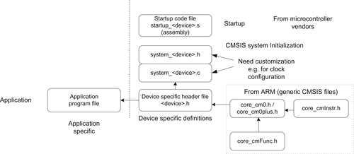
If you are using older versions of CMSIS-CORE (version 2.0 or older), you might also find that you need to include a file called core_cm0.c in the CMSIS-CORE package for some of the core functions like access to special registers and couple of intrinsic functions. These files are no longer required in newer versions of CMSIS-CORE as the functions have been incorporated directly into the header files.
14.3. Introduction of the Hardware
There are many different types of microcontroller development boards on the market and it is impossible to cover them all. Here I will cover a few choices that I used to set up the examples in this book.
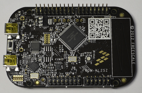
14.3.1. Freescale Freedom Board (FRDM-KL25Z)
The Freescale Freedom FRDM-KL25Z board (Figure 14.6) is based on the Freescale MKL25Z128VLK4 microcontroller. This is based on the Cortex®-M0+ processor and comes with 128-KB flash and 16-KB SRAM.
This development board included an on board debug adaptor which is CMSIS-DAP compatible and support virtual COM part (to support UART communication via USB). It also works with mbed™ development environment. In addition to Freescale Web site, wide range of resources about this board can be found on http://developer.mbed.org/platforms/KL25Z/.
Before using the FRDM-KL25Z board with Keil MDK, the on board firmware for the debug adaptor need to be updated. Please refer to the instructions on mbed Web page: http://mbed.org/handbook/Firmware-FRDM-KL25Z.
For Windows users, you might also need to install device driver to enable the CMSIS-DAP and USB virtual com port: http://developer.mbed.org/handbook/Windows-serial-configuration.
14.3.2. STMicroelectronics STM32L0 Discovery
The STM32L0 Discovery (Figure 14.7) is based on the STM32L053C8T6, a microcontroller based on the Cortex-M0+ processor, and comes with 64-KB flash and 8-KB SRAM.
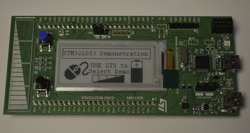
There are several useful features about the STM32L0 Discovery board:
• It can be plugged into breadboards for prototyping.
• It included an on board debug adaptor called ST-LINK v2-1, and the debug adaptor support virtual COM port feature.
• It included an E-paper display with 172 × 72 screen size.
Before using the STM32L0 Discovery with Keil MDK, you must:
1. Install the device driver for ST-LINK v2-1. (This is needed even the system have ST-LINK v2 driver installed previously). The device driver can be downloaded from http://www.st.com/web/catalog/tools/FM147/SC1887/PF260218.
2. The latest ST-LINK firmware needs to be installed to the board. The firmware and the instructions for the installation can be found here: http://developer.mbed.org/teams/ST/wiki/Nucleo-Firmware.
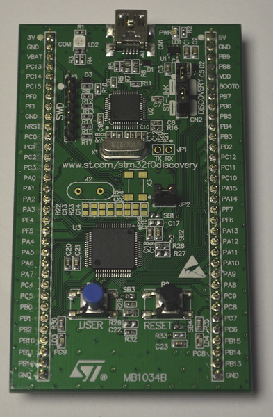
14.3.3. STMicroelectronics STM32F0 Discovery
The STM32F0 Discovery (Figure 14.8) is based on the STM32F051R8T6, a microcontroller based on the Cortex-M0 processor, and comes with 64-KB flash and 8-KB SRAM.
This low cost board has a debug adaptor included called ST-LINK v2. Similar to the STM32L0 Discovery, you can plug this board on a breadboard for prototyping. However, it does not have virtual COM port feature, so an additional adaptor is needed to handle UART communication between this board and the personal computer.
Before using the STMF0Discovery board with Keil MDK, you need to install the ST-LINK v2 device driver. After the Keil MDK is installed, the ST-LINK v2 Driver installation files can be located in C:KeilARMSTLinkUSBDriver or C:Keil_v5ARMSTLinkUSBDriver.
14.3.4. NXP LPC1114FN28
The last one covered here is a Cortex-M0 processor-based microcontroller in a 28-pin DIP package. The NXP LPC1114FN28 can easily be used by hobbyists to create applications on breadboards (Figure 14.9) or homemade PCBs.
In Figure 14.9, the left-hand side is a voltage regulator module for breadboards and the connector on the right is for debug connection. (For more details about debug connection, please refer to appendix H, A breadboard project with an ARM® Cortex-M0 microcontroller.)

As you can see from Figure 14.9, it is easy to construct a minimum system for breadboard. To use this with Keil MDK, a separate USB debug adaptor such as a ULINK™2 is required.
The LPC1114FN28 microcontroller includes a 12-MHz internal RC oscillator inside. So the external crystal is optional. However, if your application requires a clock source with high precision, then an external crystal is often necessary.
The details of the circuit construction are covered in appendix H.
14.4. Getting Started with μVision® IDE
14.4.1. What Are Needed to Start
To start with creating of your first project, we assume that:
• You have version 5 of Keil MDK and the software pack (for the microcontroller you are using) installed. The examples shown here are based on Keil MDK 5.12.
• You have access to a Cortex®-M0/Cortex-M0+ development board. (If not, you can test some of the examples using the built-in instruction set simulator.)
• A debug adaptor (either built-in in the development board or a stand-alone one) that is supported by Keil MDK.
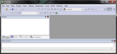
14.4.2. Starting Keil MDK
When the Keil MDK started, a screen similar to Figure 14.10 is shown.
We start by creating a new project. This can be done by using the pull-down menu: select Project → New μVision Project, as shown in Figure 14.11.

For the first project, we are going to create a simple program that toggles an LED. We will call this project “blinky.” The location of the project depends on your preference, in this demonstration we put the project in:
• For Freescale FRDM-KL25Z: C:CM0Book_Examplesch_14kl25zlinky (Section 14.4.3)
• For STM32L0 Discovery: C:CM0Book_Examplesch_14_stm32l0_blinky (Section 14.4.4)
• For STM32F0 Discovery: C:CM0Book_Examplesch_14_stm32f0_blinky (Section 14.4.5)
• For LPC1114FN28: C:CM0Book_Examplesch_14_lpc1114_blinky (Section 14.4.6)
14.4.3. Project Setup Steps for Freescale FRDM-KL25Z
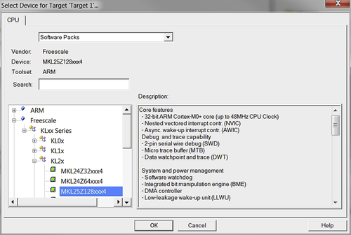
The next step of the project creation wizard defines the microcontroller to be used for the project. For FRDM-KL25Z hardware, MKL25Z128xxx4 is selected, as shown in Figure 14.12.
Now the screen switches to a Run-Time Environment manager which allows us to include the software component used. In order to simplify the project setup, the CMSIS-CORE and the device-specific start-up code options are selected, as shown in Figure 14.13.
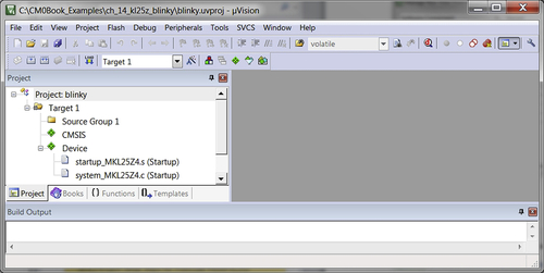
Now a project with the start-up codes is generated, as shown in Figure 14.14.
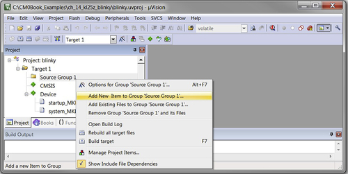
Then we add a new file to the project by right click on “Source Group 1,” and select “Add New Item…,” as shown in Figure 14.15.
A new window dialog as in Figure 14.16 is shown. We select C file and enter “blinky” as the file name.
Now we can expand “Source Group 1” and open the “blinky.c,” and add the project code, as shown in Figure 14.17.

The program that is created carried out a few operation steps:
• Update the SystemCoreClock variable (optional)
• Configure the GPIO ports for LED outputs

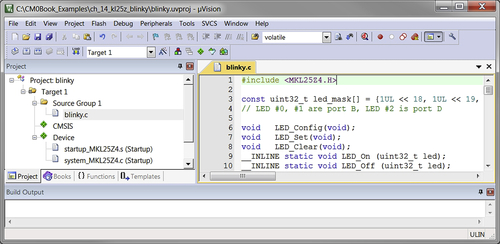
The full program code of the blinky program is shown below.
Clock Configuration Settings
The next step is to define the clock configuration (this step is optional for this project). Inside the project, we can see “system_MKL25Z4.c.” We can open this file and edit the CLOCK_SETUP to 1. This gives us a 48-MHz processor clock and a 24-MHz bus clock as the system starts up.
Project Settings
After the project and program files are created, it is often necessary to adjust a few project settings before the application can be downloaded to the microcontroller's flash memory and be tested. In most cases, the Keil μVision IDE will set up all the required microcontroller-specific settings automatically once the device is selected. However, we still need to set up:
• Debug settings
• Compiler optimization settings
It is useful to understand what settings are available and what settings are needed to get a project to work.
There are many project settings available; first we will introduce the settings that are essential for getting the program code downloaded to the flash and executing it. The project settings menu can be accessed by:
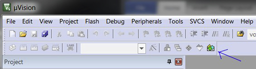
• Target option button on the tool bar  .
.
• Pull-down menu: Project → Option for Target.
• Right click on the project target name (e.g., “Target 1”) in the project window, and select options for target.
• Hot key Alt-F7.
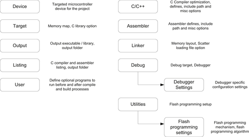
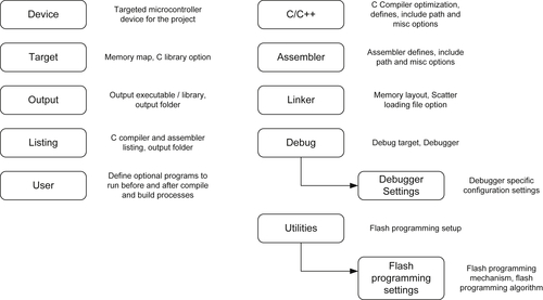
The project option menu contains a number of tabs, as shown in Figure 14.18.
By default, the Keil μVision IDE automatically sets up the memory map for us when we select the microcontroller device. In most cases, we do not need to change the memory settings. However, if the program operation fails or if flash programming is not functioning correctly, we need to go through the settings to make sure that they were not accidentally changed to incorrect values.
Debugger Settings
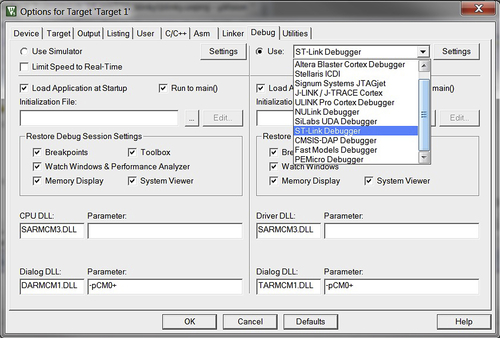
Some settings have to be set up manually. An example would be the debugger configuration because μVision IDE does not know which in-circuit debugger you will be using. First, we look at the debug options as shown in Figure 14.19. In here, we selected “CMSIS-DAP” for FRDM-KL25Z. For other development boards, you can change the settings to use other supported debugger.


We can now plug in the development board to the USB port. A window pop up might shows the board is connected as a USB mass storage. That is normal as the USB debug adaptor supports multifunctions. Now we need to set up the settings for the CMSIS-DAP debug adaptor by clicking on the “Settings” button next to it.
Since the KL25Z microcontroller does not support JTAG, in the CMSIS-DAP setting, we must select SW (Serial Wire) protocol as shown in Figure 14.20. Otherwise, you should see “RDDI-DAP Error” status in the JTAG Device Chain window of this dialog.
From the SW Device status, it shows that the debugger can read the IDCODE of the debug interface and from that we now know that the debugger can communicate with the board. In some cases, you might also need to adjust the maximum clock frequency for the debug communication. This depends on the microcontroller device, the circuit board (PCB) design as well as the debug cable length.
In normal cases, the flash programming option should be set up correctly by the tool when you select the microcontroller device. For example, the flash programming options for the KL25Z device is set up automatically by Keil MDK (Figure 14.21). However, in a few cases you might need to set up this manually.
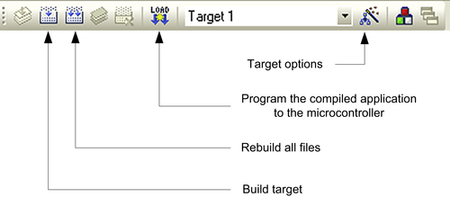
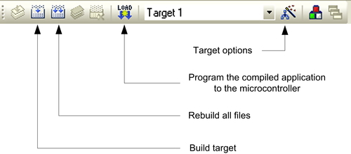
Compilation
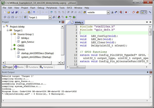
After the project options are set, we can now start the program compilation and test the program. The compile process can be carried out by a number of buttons on the tool bar as shown in Figure 14.22. Simply click on the “Build Target” button to start the compile process, use the pull-down menu (in the Project menu → Build Target), or use hot key F7. After the program is compiled and linked, we will see the compile status message as shown in Figure 14.23.

The program can then be tested by starting a debug session by using pull-down menu (Debug → Start/Stop Debug session), by clicking on the debug session button  on the tool bar, or using the hot key Ctrl-F5. When starting the debug session, the compiled image should be programmed on the microcontroller, as shown in Figure 14.24. If not, you can download the image using the “Load” button on the tool bar.


After the program is downloaded to the microcontroller, the window will change into a debugger session mode, as shown in Figure 14.25.
Now we can start the program execution using the Run button, as shown in Figure 14.26, or start the program execution using hot key F5, or using pull-down menu (Debug → Run).


Now you should see the LED on the board blinking. Congratulation! You have got the blinky project working. You can close the debug session using the debug session button  on the tool bar, or using the hot key Ctrl-F5, or from the pull-down menu (Debug → Start/Stop Debug Session).
14.4.4. Project Setup Steps for STMicroelectronics STM32L0 Discovery
For the STM32L0 Discovery board, we are going to create the example blinky project in C:CM0Book_Examplesch_14_stm32l0_blinky.
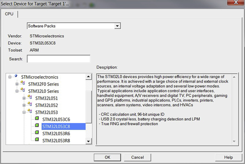
The next step of the project creation wizard defines the microcontroller to be used for the project. For the STM32L0 Discovery board, the STM32L053C8 device is selected, as shown in Figure 14.27.
Now the screen switches to a Run-Time Environment manager which allows us to include the software component used. In order to simplify the project setup, the CMSIS-CORE and the device-specific start-up code options are selected, as shown Figure 14.28.
Now a project with the start-up codes is generated, as shown in Figure 14.29.


Then we add a new file to the project by right clicking on “Source Group 1,” and select “Add New Item…,” as shown in Figure 14.30.
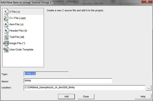
A new window dialog as in Figure 14.31 is shown. We select C file and enter blinky as the file name.
Now we can expand “Source Group 1” and open the “blinky.c,” and add the project code, as shown in Figure 14.32. In order to help GPIO setup, we also added a separate C file to handle GPIO configuration functions.


The program that is created carried out a few operation steps:
• Configure the GPIO ports for LED outputs
• Enter a simple loop to turn on and off the LEDs, with a delay specified by a C macro called LOOP_COUNT
The full program code of the blinky program is shown below.
The GPIO functions file is:
And a header file is used to define constants for GPIO configurations:
Project Settings
After the project and program files are created, it is often necessary to adjust a few project settings before the application can be downloaded to the microcontroller's flash memory and be tested. In most cases, the Keil μVision IDE will set up all the required microcontroller-specific settings automatically once the device is selected. However, we still need to set up:
• Debug settings
• Compiler optimization settings
It is useful to understand what settings are available and what settings are needed to get a project to work.
There are many project settings available; first we will introduce the settings that are essential for getting the program code downloaded to the flash and executing it. The project settings menu can be accessed by:
• Target option button on the tool bar  .
.
• Pull-down menu: Project → Option for Target.
• Right click on the project target name (e.g., “Target 1”) in the project window, and select options for target.
• Hot key Alt-F7.
The project option menu contains a number of tabs, as shown in Figure 14.33.
By default, the Keil μVision IDE automatically sets up the memory map for us when we select the microcontroller device. In most cases, we do not need to change the memory settings. However, if the program operation fails or if flash programming is not functioning correctly, we need to go through the settings to make sure that they were not accidentally changed to incorrect values.
Debugger Settings
Some settings have to be set up manually. An example would be the debugger configuration because μVision IDE does not know which in-circuit debugger you will be using. First, we look at the debug options as shown in Figure 14.34. Here, we selected “ST-LINK” for the STM32L0 Discovery board. For other development boards you can change the settings to use other supported debugger.
We can now plug in the development board to the USB port. A window pop up might show the board is connected as a USB mass storage. That is normal as the USB debug adaptor supports multifunctions. Now we need to set up the settings for the ST-LINK debug adaptor by clicking on the “Settings” button next to it.
Since the STM32L053C8 microcontroller does not support JTAG, in the ST-LINK setting, we must select SW (Serial Wire) protocol as shown in Figure 14.35. Otherwise an error message would be shown to indicate that STM32F0 and L0 series do not support JTAG.
From the SW Device status, it shows that the debugger can read the IDCODE of the debug interface and from that we now know that the debugger can communicate with the board. In some cases, you might also need to adjust the maximum clock frequency for the debug communication. This depends on the microcontroller device, the circuit board (PCB) design as well as the debug cable length.


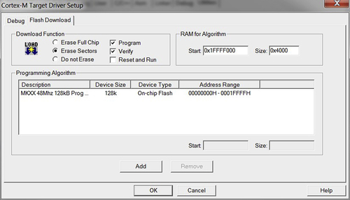
In normal cases, the flash programming option should be set up correctly by the tool when you select the microcontroller device. For example, the flash programming options for the STM32L0 device is set up automatically by Keil MDK (Figure 14.36). However, in a few cases you might need to set up this manually.
Compilation
After the project options are set, we can now start the program compilation and test the program. The compile process can be carried out by a number of buttons on the tool bar as shown in Figure 14.37. Simply click on the “Build Target” button to start the compile process, use the pull-down menu (in the Project menu → Build Target), or use hot key F7. After the program is compiled and linked, we will see the compile status message as shown in Figure 14.38.
The program can then be tested by starting a debug session by using pull-down menu (Debug → Start/Stop Debug session), by clicking on the debug session button  on the tool bar, or using the hot key Ctrl-F5. When starting the debug session, the compiled image should be programmed on the microcontroller, as shown in Figure 14.39. If not, you can download the image using the “Load” button on the tool bar.

After the program is downloaded to the microcontroller, the window will change into a debugger session mode, as shown in Figure 14.40.
Now we can start the program execution using the Run button, as shown in Figure 14.41, or start the program execution using hot key F5, or using pull-down menu (Debug → Run).
Now you should see the LEDs on the board blinking. Congratulation! You have got the blinky project working. You can close the debug session using the debug session button  on the tool bar, or using the hot key Ctrl-F5, or from the pull-down menu (Debug → Start/Stop Debug Session).
14.4.5. Project Setup Steps for STMicroelectronics STM32F0 Discovery
For the STM32F0 Discovery board, we are going to create the example blinky project in C:CM0Book_Examplesch_14_stm32f0_blinky.
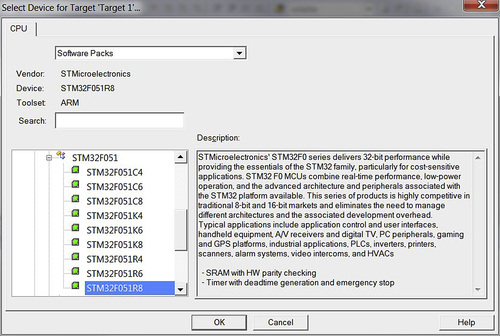
The next step of the project creation wizard defines the microcontroller to be used for the project. For the STM32F0 Discovery hardware, STM32F051R8 is selected, as shown in Figure 14.42.
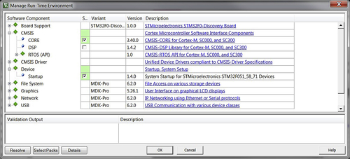
Now the screen switches to a Run-Time Environment manager which allows us to include the software component used. In order to simplify the project setup, the CMSIS-CORE and the device-specific start-up code options are selected, as shown Figure 14.43.
Now a project with the start-up codes is generated, as shown in Figure 14.44.
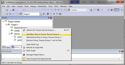
Then we add a new file to the project by right clicking on “Source Group 1,” and select “Add New Item…,” as shown in Figure 14.45.
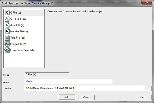
A new window dialog as in Figure 14.46 is shown. We select C file and enter blinky as the file name.
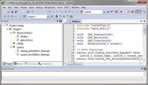
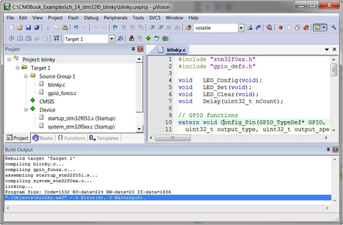
Now we can expand “Source Group 1” and open the “blinky.c,” and add the project code, as shown in Figure 14.47. In order to help GPIO setup, we also added a separate C file to handle GPIO configuration functions.

The program that is created carried out a few operation steps:
• Configure the GPIO ports for LED outputs
The full program code of the blinky program is shown below.
The GPIO functions file is:
And a header file is used to define constants for GPIO configurations:
Project Settings
After the project and program files are created, it is often necessary to adjust a few project settings before the application can be downloaded to the microcontroller's flash memory and be tested. In most cases, the Keil μVision IDE will set up all the required microcontroller-specific settings automatically once the device is selected. However, we still need to set up:
• Debug settings
• Compiler optimization settings
It is useful to understand what settings are available and what settings are needed to get a project to work.
There are many project settings available; first we will introduce the settings that are essential for getting the program code downloaded to the flash and executing it. The project settings menu can be accessed by:
• Target option button on the tool bar  .
.
• Pull-down menu: Project → Option for Target.
• Right click on the project target name (e.g., “Target 1”) in the project window, and select options for target.
• Hot key Alt-F7.
The project option menu contains a number of tabs, as shown in Figure 14.48.

By default, the Keil μVision IDE automatically sets up the memory map for us when we select the microcontroller device. In most cases, we do not need to change the memory settings. However, if the program operation fails or if flash programming is not functioning correctly, we need to go through the settings to make sure that they were not accidentally changed to incorrect values.
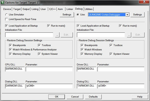
Debugger Settings
Some settings have to be set up manually. An example would be the debugger configuration because μVision IDE does not know which in-circuit debugger you will be using. First, we look at the debug options as shown in Figure 14.49. Here, we selected “ST-LINK” for STM32F0 Discovery. For other development boards you can change the settings to use other supported debugger.

We can now plug in the development board to the USB port. Now we need to set up the settings for the ST-LINK debug adaptor by click on the “Settings” button next to it.
Since the STM32F051R8 microcontroller does not support JTAG, in the ST-LINK setting, we must select SW (Serial Wire) protocol as shown in Figure 14.50. Otherwise an error message would be shown to indicate that STM32F0 and L0 series do not support JTAG.

From the SW Device status, it shows that the debugger can read the IDCODE of the debug interface and from that we now know that the debugger can communicate with the board. In some cases, you might also need to adjust the maximum clock frequency for the debug communication. This depends on the microcontroller device, the circuit board (PCB) design as well as the debug cable length.
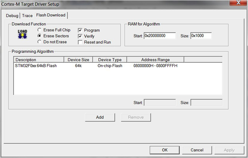
In normal cases the flash programming option should be set up correctly by the tool when you select the microcontroller device. For example, the flash programming options for the STM32F0 device is set up automatically by Keil MDK (Figure 14.51). However, in a few cases you might need to set up this manually.
Compilation
After the project options are set, we can now start the program compilation and test the program. The compile process can be carried out by a number of buttons on the tool bar as shown in Figure 14.52. Simply click on the “Build Target” button to start the compile process, use the pull-down menu (in the Project menu → Build Target), or use hot key F7. After the program is compiled and linked, we will see the compile status message as shown in Figure 14.53.

The program can then be tested by starting a debug session by using pull-down menu (Debug → Start/Stop Debug session), by clicking on the debug session button  on the tool bar, or using the hot key Ctrl-F5. When starting the debug session, the compiled image should be programmed on the microcontroller, as shown in Figure 14.54. If not, you can download the image using the “Load” button on the tool bar.

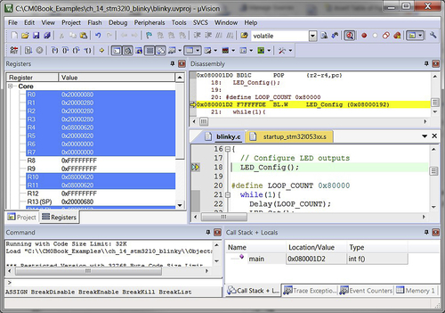
After the program is downloaded to the microcontroller, the window will change into a debugger session mode, as shown in Figure 14.55.
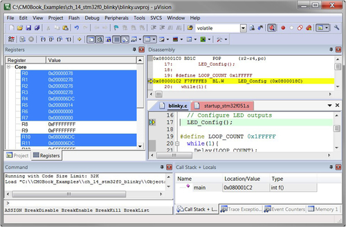
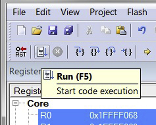
Now we can start the program execution using the Run button, as shown in Figure 14.56, or start the program execution using hot key F5, or using pull-down menu (Debug → Run).

14.4.6. Project Setup Steps for NXP LPC1114FN28
The example setup described in this section is based on a breadboard circuit construction as described in appendix H. Please refer to this appendix for details on the hardware setup. After this is done, we can then create the first blinky project following the instructions illustrated here. Here, we assume that you are using Keil ULINK™2/ULINK Pro debug adaptor. If a different adaptor is used, the debug configuration options would be different from what we have shown here.
For the LPC1114FN28 microcontroller device, we are going to create the example blinky project in C:CM0Book_Examplesch_14_lpc1114_blinky.
The next step of the project creation wizard defines the microcontroller to be used for the project. For this project, the LPC1114FN28/102 is selected, as shown in Figure 14.57.
Now the screen switches to a Run-Time Environment manager which allows us to include the software component used. In order to simplify the project setup, the CMSIS-CORE and the device-specific start-up code options are selected, as shown Figure 14.58.


Now a project with the start-up codes is generated, as shown in Figure 14.59.
Then we add a new file to the project by right clicking on “Source Group 1,” and select “Add New Item…,” as shown in Figure 14.60.
A new window dialog as in Figure 14.61 is shown. We select C file and enter blinky as the file name.


Now we can expand “Source Group 1” and open the “blinky.c,” and add the project code, as shown in Figure 14.62. For this project, we assume that the LED is connected to pin 5 of port 1.
The program that is created carried out a few operation steps:
• Configure the GPIO ports for LED outputs
• Enter a simple loop to turn on and off the LED, with a delay specified by a C macro called LOOP_COUNT
The full program code of the blinky program is shown below.
Project Settings
After the project and program files are created, it is often necessary to adjust a few project settings before the application can be downloaded to the microcontroller's flash memory and be tested. In most cases, the Keil μVision IDE will set up all the required microcontroller-specific settings automatically once the device is selected. However, we still need to set up:
• Debug settings
• Compiler optimization settings
It is useful to understand what settings are available and what settings are needed to get a project to work.
There are many project settings available; first we will introduce the settings that are essential for getting the program code downloaded to the flash and executing it. The project settings menu can be accessed by:
• Target option button on the tool bar  .
.
• Pull-down menu: Project → Option for Target.
• Right click on the project target name (e.g., “Target 1”) in the project window, and select options for target.
• Hot key Alt-F7.
The project option menu contains a number of tabs, as shown in Figure 14.63.
By default, the Keil μVision IDE automatically sets up the memory map for us when we select the microcontroller device. In most cases, we do not need to change the memory settings. However, if the program operation fails or if flash programming is not functioning correctly, we need to go through the settings to make sure that they were not accidentally changed to incorrect values.

Debugger Settings
Some settings have to be set up manually. An example would be the debugger configuration because μVision IDE does not know which in-circuit debugger you will be using. First we look at the debug options as shown in Figure 14.64. Here, we selected “ULINK2/ME.” You might need to select other debug adaptor based on the hardware you have.
We can now plug in the breadboard and connect the ULINK2 to the USB port. Next we need to set up the settings for the ULINK2 debug adaptor by clicking on the “Settings” button next to it.
Since the LPC1114FN28 microcontroller does not support JTAG, in the ULINK2 settings, we must select SW (Serial Wire) protocol as shown in Figure 14.65. Otherwise nothing will show up in the JTAG device chain window.
Several options need a bit of attention here:
• The maximum SW clock is reduced to 200 KHz. Typically on breadboard environment, there can be higher electrical noise and therefore might need a slower debug communication speed for reliable debug operations.
• The Reset type is set to SYSRESETREQ (System Reset Request). This ensures that the debugger correctly resets the microcontroller when entering debug session.

From the SW Device status, it shows that the debugger can read the IDCODE of the debug interface and from that we now know that the debugger can communicate with the board. In some cases, you might also need to further reduce the maximum clock frequency for the debug communication. This depends on the microcontroller device, the circuit board (PCB) design as well as the debug cable length.
In normal cases, the flash programming option should be set up correctly by the tool when you select the microcontroller device. For example, the flash programming options for the LPC1114FN28 device is set up automatically by Keil MDK (Figure 14.66). However, in a few cases you might need to set up this manually.

Compilation
After the project options are set, we can now start the program compilation and test the program. The compile process can be carried out by a number of buttons on the tool bar as shown in Figure 14.67. Simply click on the “Build Target” button to start the compile process, use the pull-down menu (in the Project menu → Build Target), or use hot key F7. After the program is compiled and linked, we will see the compile status message as shown in Figure 14.68.
The program can then be tested by starting a debug session by using pull-down menu (Debug → Start/Stop Debug session), by clicking on the debug session button  on the tool bar, or using the hot key Ctrl-F5. When starting the debug session, the compiled image should be programmed on the microcontroller, as shown in Figure 14.69. If not, you can download the image using the “Load” button on the tool bar.

After the program is downloaded to the microcontroller, the window will change into a debugger session mode, as shown in Figure 14.70.


Now we can start the program execution using the Run button, as shown in Figure 14.71, or start the program execution using hot key F5, or using pull-down menu (Debug → Run).
Now you should see the LEDs on the board blinking. Congratulation! You have got the blinky project working. You can close the debug session using the debug session button  on the tool bar, or using the hot key Ctrl-F5, or from the pull-down menu (Debug → Start/Stop Debug Session).
..................Content has been hidden....................
You can't read the all page of ebook, please click here login for view all page.