
Advanced Programming Features and System Behavior
Publisher Summary
This chapter explores the possibilities of running a system with two separate stacks, double-word stack alignment, and the Non-base Thread Enable bit in the Nested Vectored Interrupt Controller (NVIC) Configuration Control register. If the optional Memory Protection Unit is implemented, it could be used to block user applications from accessing kernel stack memory so that they cannot crash the kernel by memory corruption. In applications that conform to the Procedure Call Standard for the ARM Architecture, it is necessary to ensure that the stack pointer value at function entry should be aligned to the double word address. To achieve this requirement, the stacking address of registers at exception handling is adjusted accordingly. A few aspects for getting the best out of the Cortex-M3 and a few tricks to speed up parts of the program while using assembly are discussed. Lockup situations in case of faults are explained. It is important to take extra care to prevent lockup problems when developing a non-maskable interrupt (NMI) or hard fault handler. FAULTMASK, used to escalate a configurable fault handler to hard fault level without the need to invoke hard fault by a real fault, is also explained.
12.1 Running a System with Two Separate Stacks
One of the important features of ARMv7-M architecture is the capability to allow the user application stack to be separated from the privileged/kernel stack. If the optional Memory Protection Unit (MPU) is implemented, it could be used to block user applications from accessing kernel stack memory so that they cannot crash the kernel by memory corruption.
Typically, a robust system based on the Cortex™-M3 has the following properties:
• Exception handlers using Main Stack Pointer (MSP)
• Kernel code invoked by a System Tick (SYSTICK) exception at regular intervals, running in the privileged access level for task scheduling and system management
• User applications running as threads with the user access level (nonprivileged); these applications use Process Stack Pointer (PSP)
• Stack memory for kernel and exception handlers is pointed to by the MSP, and the stack memory is restricted to privileged accesses only, if the MPU is available
• Stack memory for user applications is pointed to by the PSP
Assume that the system memory has a Static Random Access Memory (SRAM) memory and a Memory Protection Unit (MPU), we could set up the MPU so that the SRAM is divided into two regions for user and privileged access (see Figure 12.1). Each region is used by application data, as well as by stack memory space. Since stack operation in the Cortex-M3 is full descending, the initial value of stack pointers needs to be pointed to the top of the regions.

After power-up, only the MSP is initialized (by fetching address 0x0 in the power-up sequence). Additional steps are required to set up a completely robust two-stack system. For applications in assembly code, it can simply be
; Start at privileged level (this code locates in user; accessible memory)BL MpuSetup ; Setup MPU regions and enable memory ; protectionLDR R0,=PSP_TOP ; Setup Process SP to top of process stackMSR PSP, R0BL SystickSetup ; Setup Systick and systick exception to ; invoke OS kernel at regular intervalsMOV R0, #0x3 ; Setup CONTROL register so that user ; program use PSP,MSR CONTROL, R0 ; and switch current access level to userISB ; Instruction Synchronization BarrierB UserApplicationStart ; Now we are in user access ; level. Start user codeThis arrangement is fine for assembler, but for C programs, switching stack pointers in the middle of a C function can cause loss of local variables (because in C functions or subroutines, local variables may be put onto stack memory). The Cortex-M3 Technical Reference Manual (TRM) [Ref. 1] suggests that we use an interrupt service routine (ISR) like Supervisor Call (SVC) to invoke the kernel, and then change the stack pointer by modifying the EXC_RETURN value (see Figure 12.2).
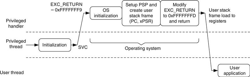
In most cases, EXC_RETURN modification and stack switching are included in the operating system (OS). After the user application starts, the SYSTICK exception can be used regularly to invoke the OS for system management and possibly arrange context switching, if needed (see Figure 12.3).

Note that context switching is carried out in PendSV (a low-priority exception) to prevent context switching at the middle of an interrupt handler.
However, many applications do not require an OS, but it is still helpful to use separate stacks for different sections of application code as a way to improve reliability. One possible way to handle this is to start Cortex-M3 with the MSP pointed to a process stack region. This way the initialization is done with the process stack region but using MSP. Before starting the user application, the following code is executed:
; Start at privileged level, MSP point to User stackMpuSetup(); // Setup MPU regions and enable memory protectionSystickSetup(); // Setup Systick and systick exception for routine // system management codeSwitchStackPointer(); // Call an assembly subroutine to switch SP /*; ------Inside SwitchStackPointer ----- PUSH {R0, R1, LR} MRS R0, MSP ; Save current stack pointer LDR R1, =MSP_TOP ; Change MSP to new location MSR MSP, R1 MSR PSP, R0 ; Store current stack pointer in PSP MOV R0, #0x3 MSR CONTROL, R0 ; Switch to user mode, and use PSP as ; current stack POP {R0, R1, PC} ; Return ; ------ Back to C program -----*/; Now we are in User mode, using PSP and the local variables; still hereUserApplicationStart(); // Start application code in user mode12.2 Double-Word Stack Alignment
In applications that conform to AAPCS1, it is necessary to ensure that the stack pointer value at function entry should be aligned to the double word address. To achieve this requirement, the stacking address of registers at exception handling is adjusted accordingly. This is a configurable option on the Cortex-M3 processor. To enable this feature, the STKALIGN bit in the Nested Vectored Interrupt Controller (NVIC) Configuration Control register needs to be set (see Table D.18 in Appendix D). For example, if CMSIS compliant device driver is used in C language project
SCB->CCR = SCB->CCR | 0x200;If the project is in C but CMSIS is not used,
#define NVIC_CCR *((volatile unsigned long *) (0xE000ED14))NVIC_CCR = NVIC_CCR | 0x200; /* Set STKALIGN in NVIC */This can also be done in assembly language
LDR R0,=0xE000ED14 ; Set R0 to be address of NVIC CCRLDR R1, [R0]ORR.W R1, R1, #0x200 ; Set STKALIGN bitSTR R1, [R0] ; Write to NVIC CCRWhen the STKALIGN bit is set during exception stacking, bit 9 of the stacked xPSR (combined Program Status Register) is used to indicate whether a stack pointer adjustment has been made to align the stacking. When unstacking, the stack pointer (SP) adjustment checks bit 9 of the stacked xPSR and adjusts the SP accordingly.
To prevent stack data corruption, the STKALIGN bit must not be changed within an exception handler. This can cause a mismatch of stack pointer location before and after the exception.
This feature is available from Cortex-M3 revision 1 onward. Early Cortex-M3 products based on revision 0 do not have this feature. In Cortex-M3 revision 2, this feature is enabled by default whereas in revision 1, this needs to be turned on by software.
This feature should be used if the AAPCS conformation is required.
12.3 Nonbase Thread Enable
In the Cortex-M3, it is possible to switch a running interrupt handler from privileged level to user access level. This is needed when the interrupt handler code is part of a user application and should not be allowed to have privileged access. This feature is enabled by the Nonbase Thread Enable (NONBASETHRDENA) bit in the NVIC Configuration Control register.
To use this feature, an exception handler redirection is involved. The vector in the vector table points to a handler running in privileged mode but located in user mode accessible memory
redirect_handler PUSH {LR} SVC 0 ; A SVC function to change from privileged to ; user mode BL User_IRQ_Handler SVC 1 ; A SVC function to change back from user to ; privileged mode POP {PC} ; ReturnThe SVC handler is divided into three parts as follows:
• Determine the parameter when calling SVC.
• SVC service #0 enables the NONBASETHRDENA, adjusts the user stack and EXC_RETURN value, and returns to the redirect handler in user mode, using the process stack.
• SVC service #1 disables the NONBASETHRDENA, restores the user stack pointer position, and returns to the redirect handler in privileged mode, using the main stack.
The SVC services are used because the only way you can change the Interrupt Status register (IPSR) is via an exception return. Other exceptions, such as software-triggered interrupts, could be used, but they are not recommended because they are imprecise and could be masked, which means that there is a possibility that the required stack copying and switch operation is not carried out immediately. The sequence of the code is illustrated in Figure 12.4, which shows the stack pointer changes and the current exception priority.

In this figure, the manual adjustment of the PSP inside the SVC services is highlighted by circles indicated by dotted lines.
12.4 Performance Considerations
To get the best out of the Cortex-M3, a few aspects need to be considered. First, we need to avoid memory wait states. During the design stage of the microcontroller or SoC, the designer should optimize the memory system design to allow instruction and data accesses to be carried out at the same time, and use 32-bit memories, if possible. For developers, the memory map should be arranged so that program code is executed from the code region and the majority of data accesses is done via the system bus. This way data accesses can be carried out at the same time as instruction fetches.
Second, the interrupt vector table should also be put into the code region, if possible. Thus, vector fetch and stacking can be carried out at the same time. If the vector table is located in the SRAM, extra clock cycles might result in interrupt latency because both vector fetch and stacking could share the same system bus (unless the stack is located in the code region, which uses a D-Code bus).
If possible, avoid using unaligned transfers. An unaligned transfer might take two or more Advanced High-Performance Bus (AHB) transfers to complete and will slow program performance, so plan your data structure carefully. In assembly language with ARM tools, you can use the ALIGN directive to ensure that a data location is aligned.
Most of you might be using C language for development, but for those who are using assembly, you can use a few tricks to speed up parts of the program.
1. Use memory access instruction with offset. When multiple memory locations in a small region are to be accessed, instead of writing
LDR R0, =0xE000E400 ; Set interrupt priority #3,#2,#1,#0
LDR R1, =0xE0C02000 ; priority levels
STR R1,[R0]
LDR R0, =0xE000E404 ; Set interrupt priority #7,#6,#5,#4
LDR R1, =0xE0E0E0E0 ; priority levels
STR R1,[R0]
you can reduce the program code to the following:
LDR R0, =0xE000E400 ; Set interrupt priority #3,#2,#1,#0
LDR R1, =0xE0C02000 ; priority levels
STR R1,[R0]
LDR R1,=0xE0E0E0E0 ; priority levels
STR R1,[R0,#4] ; Set interrupt priority #7,#6,#5,#4
The second store uses an offset of the first address and hence reduces the number of instructions.
2. Combine multiple memory accesses into Load/Store Multiple instructions (LDM/STM). The preceding example can be further reduced by using STM instruction as follows:
LDR R0,=0xE000E400 ; Set interrupt priority base
LDR R1,=0xE0C02000 ; priority levels #3,#2,#1,#0
LDR R2,=0xE0E0E0E0 ; priority levels #7,#6,#5,#4
STMIA R0, {R1, R2}
3. Use IF-THEN (IT) instruction blocks to replace small conditional branches. Since the Cortex-M3 is a pipelined processor, a branch penalty happens when a branch operation is taken. If the conditional branch operation is used to skip a few instructions, this can be replaced by the IT instruction block, which might save a few clock cycles.
4. If an operation can be carried out by either two Thumb® instructions or a single Thumb-2 instruction, the Thumb-2 instruction method should be used because it gives a shorter execution time, despite the fact that the memory size is the same.
12.5 Lockup Situations
When an error condition occurs, the corresponding fault handler will be triggered. If another fault takes place inside the usage fault/bus fault/memory management fault handler, the hard fault handler will be triggered. However, what if we get another fault inside the hard fault handler? In this case, a lockup situation will take place (see Figure 12.5).
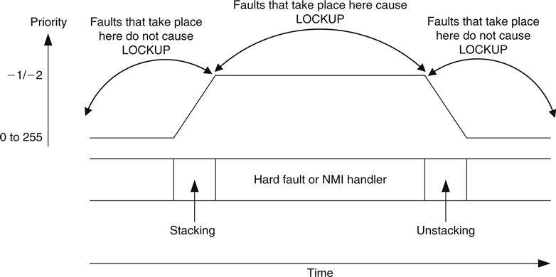
12.5.1 What Happens During Lockup?
During lockup, the program counter will be forced to 0xFFFFFFFX and will keep fetching from that address. In addition, an output signal called LOCKUP from the Cortex-M3 will be inserted to indicate the situation. Chip designers might use this signal to trigger a reset at the system reset generator.
Lockup can take place when
• Faults occur inside the hard fault handler (double fault)
• Faults occur inside the nonmaskable interrupt (NMI) handler
• Bus faults occur during the reset sequence (initial SP or program counter (PC) fetch)
For double-fault situations, it is still possible for the core to respond to an NMI and execute the NMI handler. But after the handler completes, it will return to the lockup state, with the program counter restored to 0xFFFFFFFX. In this case, the system locks up and the current priority level is held at -1. If an NMI occurs, the processor will still preempt and execute the NMI handler because the NMI has a higher priority (-2) than the current priority level (-1). When the NMI is complete and returns to the lockup state, the current exception priority is returned to -1.
Normally, the best way to exit a lockup is to perform a reset. Alternatively, for a system with a debugger attached, it is possible to halt the core, change the PC to a different value, and start the program execution from there. In most cases this might not be a good idea, since a number of registers, including the interrupt system, might need reinitialization before the system can be returned to normal operation.
You might wonder why we do not simply reset the core when a lockup takes place. You might want to do that in a live system, but during software development, we should first try to find out the cause of the problem. If we reset the core immediately, we might not be able to analyze what went wrong because registers will be reset and hardware status will be changed. In most Cortex-M3 microcontrollers, a watchdog timer can be used to reset the core if it enters the lockup state.
Note that a bus fault that occurs during stack when entering a hard fault handler or NMI handler does not cause lockup, but the bus fault handler will be pended.
12.5.2 Avoiding Lockup
It is important to take extra care to prevent lockup problems when you're developing an NMI or hard fault handler. For example, we can avoid unnecessary stack accesses in a hard fault handler unless we know that the memory is functioning correctly and the stack pointer is still valid. In developing complex systems, one of the possible causes of a bus fault or memory fault is stack pointer corruption. If we start the hard fault handler with something like this
hard_fault_handlerPUSH {R4-R7,LR} ; Bad idea unless you are sure that the ; stack is safe to use! . . .and if the fault was caused by a stack error, we could enter lockup in our hard fault handler straight away. In general, when programming hard fault, bus fault, and memory management fault handlers, it might be worth checking whether the stack pointer is in a valid range before we carry out more stack operations. For coding NMI handlers, we can try to reduce risk caused by stack operation by using R0–R3 and R12 only, since they are already stacked.
One approach for developing hard fault and NMI handlers is to carry out only the essential tasks inside the handlers, and the rest of the tasks, such as error reporting, can be pended using a separate exception, such as PendSV or a software interrupt. This helps to ensure that the hard fault handler or NMI is small and robust.
Furthermore, we should ensure that the NMI and hard fault handler code will not try to use SVC instructions. Since SVC always has lower priority than hard fault and NMI, using SVC in these handlers will cause lockup. This might look simple, but when your application is complex and you call functions from different files in your NMI and hard fault handler, you might accidentally call a function that contains an SVC instruction. Therefore, before you develop your software, you need to carefully plan the SVC implementation.
12.6 FAULTMASK
FAULTMASK is used to escalate a configurable fault handler (bus fault, usage fault or memory management fault) to hard fault level without the need to invoke hard fault by a real fault. This allows the configurable fault handler to pretend to be the hard fault handler. By doing this, the fault handler can have the ability to
1. Mask bus fault by setting HFHFNMIGN in Configuration Control register. It can be used to probe the bus system without causing lockup. For example, for checking if a bus bridge is working correctly.
2. Bypass the MPU. This allows the fault handler to access an MPU protected memory location without reprogramming the MPU just to carry out a few transfers to fix faults.
The FAULTMASK usage is different from PRIMASK. PRIMASK is generally used in timing critical code, but it doesn't have the ability to mask bus fault or bypass MPU. With PRIMASK set, all configurable faults will be escalated to hard fault handler. FAULTMASK is used to allow a configurable fault handler to solve memory-related problems by using features normally only available for a hard fault handler. However, when FAULTMASK is set, faults such as incorrect undefined instruction, or using SVC in the wrong priority level, can still cause lockup.