
The Cortex-M3 Instruction Set, Reference Material
This appendix is the Cortex™-M3 instruction set description from the ARM Cortex-M3 user guide reference material; it is reproduced with permission from ARM. The following sections give general information:
Each of the following sections describes a functional group of Cortex-M3 instructions. Together they describe all the instructions supported by the Cortex-M3 processor:
• Memory access instructions on page 361
• General data-processing instructions on page 373
• Multiply and divide instructions on page 383
• Saturating instructions on page 386
• Bitfield instructions on page 388
A.1 Instruction Set Summary
The processor implements a version of the Thumb® instruction set. Table A.1 lists the supported instructions.
Table A.1
| Mnemonic | Operands | Brief Description | Flags | Page |
| ADC, ADCS | {Rd,} Rn, Op2 | Add with Carry | N,Z,C,V | Page 374 |
| ADD, ADDS | {Rd,} Rn, Op2 | Add | N,Z,C,V | Page 374 |
| ADD, ADDW | {Rd,} Rn, #imm12 | Add | N,Z,C,V | Page 374 |
| ADR | Rd, label | Load PC-relative address | — | Page 362 |
| AND, ANDS | {Rd,} Rn, Op2 | Logical AND | N,Z,C | Page 376 |
| ASR, ASRS | Rd, Rm, <Rs|#n> | Arithmetic Shift Right | N,Z,C | Page 377 |
| B | Label | Branch | — | Page 391 |
| BFC | Rd, #lsb, #width | Bit Field Clear | — | Page 388 |
| BFI | Rd, Rn, #lsb, #width | Bit Field Insert | — | Page 388 |
| BIC, BICS | {Rd,} Rn, Op2 | Bit Clear | N,Z,C | Page 376 |
| BKPT | #imm | Breakpoint | — | Page 397 |
| BL | Label | Branch with Link | — | Page 391 |
| BLX | Rm | Branch indirect with Link | — | Page 391 |
| BX | Rm | Branch indirect | — | Page 391 |
| CBNZ | Rn, label | Compare and Branch if Nonzero | — | Page 393 |
| CBZ | Rn, label | Compare and Branch if Zero | — | Page 393 |
| CLREX | — | Clear Exclusive | — | Page 372 |
| CLZ | Rd, Rm | Count leading zeros | — | Page 378 |
| CMN | Rn, Op2 | Compare Negative | N,Z,C,V | Page 378 |
| CMP | Rn, Op2 | Compare | N,Z,C,V | Page 378 |
| CPSID | iflags | Change Processor State, Disable Interrupts | — | Page 398 |
| CPSIE | iflags | Change Processor State, Enable Interrupts | — | Page 398 |
| DMB | — | Data Memory Barrier | — | Page 398 |
| DSB | — | Data Synchronization Barrier | — | Page 399 |
| EOR, EORS | {Rd,} Rn, Op2 | Exclusive OR | N,Z,C | Page 376 |
| ISB | — | Instruction Synchronization Barrier | — | Page 399 |
| IT | — | If-Then condition block | — | Page 393 |
| LDM | Rn{!}, reglist | Load Multiple registers, increment after | — | Page 368 |
| LDMDB, LDMEA | Rn{!}, reglist | Load Multiple registers, decrement before | — | Page 368 |
| LDMFD, LDMIA | Rn{!}, reglist | Load Multiple registers, increment after | — | Page 368 |
| LDR | Rt, [Rn, #offset] | Load Register with word | — | Page 362 |
| LDRB, LDRBT | Rt, [Rn, #offset] | Load Register with byte | — | Page 362 |
| LDRD | Rt, Rt2, [Rn, #offset] | Load Register with 2 bytes | — | Page 362 |
| LDREX | Rt, [Rn, #offset] | Load Register Exclusive | — | Page 371 |
| LDREXB | Rt, [Rn] | Load Register Exclusive with byte | — | Page 371 |
| LDREXH | Rt, [Rn] | Load Register Exclusive with halfword | — | Page 371 |
| LDRH, LDRHT | Rt, [Rn, #offset] | Load Register with halfword | — | Page 362 |
| LDRSB, LDRSBT | Rt, [Rn, #offset] | Load Register with signed byte | — | Page 362 |
| LDRSH, LDRSHT | Rt, [Rn, #offset] | Load Register with signed halfword | — | Page 362 |
| LDRT | Rt, [Rn, #offset] | Load Register with word | — | Page 362 |
| LSL, LSLS | Rd, Rm, <Rs|#n> | Logical Shift Left | N,Z,C | Page 377 |
| LSR, LSRS | Rd, Rm, <Rs|#n> | Logical Shift Right | N,Z,C | Page 377 |
| MLA | Rd, Rn, Rm, Ra | Multiply with Accumulate, 32-bit result | — | Page 383 |
| MLS | Rd, Rn, Rm, Ra | Multiply and Subtract, 32-bit result | — | Page 383 |
| MOV, MOVS | Rd, Op2 | Move | N,Z,C | Page 379 |
| MOVT | Rd, #imm16 | Move Top | — | Page 381 |
| MOVW, MOV | Rd, #imm16 | Move 16-bit constant | N,Z,C | Page 379 |
| MRS | Rd, spec_reg | Move from special register to general register | — | Page 400 |
| MSR | spec_reg, Rm | Move from general register to special register | N,Z,C,V | Page 400 |
| MUL, MULS | Rd, Rn, Rm | Multiply, 32-bit result | N,Z | Page 383 |
| MVN, MVNS | Rd, Op2 | Move NOT | N,Z,C | Page 379 |
| NOP | — | No Operation | — | Page 401 |
| ORN, ORNS | {Rd,} Rn, Op2 | Logical OR NOT | N,Z,C | Page 376 |
| ORR, ORRS | {Rd,} Rn, Op2 | Logical OR | N,Z,C | Page 376 |
| POP | reglist | Pop registers from stack | — | Page 370 |
| PUSH | reglist | Push registers onto stack | — | Page 370 |
| RBIT | Rd, Rn | Reverse bits | — | Page 381 |
| REV | Rd, Rn | Reverse byte order in a word | — | Page 381 |
| REV16 | Rd, Rn | Reverse byte order in each halfword | — | Page 381 |
| REVSH | Rd, Rn | Reverse byte order in bottom halfword and sign extend | — | Page 381 |
| ROR, RORS | Rd, Rm, <Rs|#n> | Rotate Right | N,Z,C | Page 377 |
| RRX, RRXS | Rd, Rm | Rotate Right with Extend | N,Z,C | Page 377 |
| RSB, RSBS | {Rd,} Rn, Op2 | Reverse Subtract | N,Z,C,V | Page 374 |
| SBC, SBCS | {Rd,} Rn, Op2 | Subtract with Carry | N,Z,C,V | Page 374 |
| SBFX | Rd, Rn, #lsb, #width | Signed Bit Field Extract | — | Page 389 |
| SDIV | {Rd,} Rn, Rm | Signed Divide | — | Page 386 |
| SEV | — | Send Event | — | Page 402 |
| SMLAL | RdLo, RdHi, Rn, Rm | Signed Multiply with Accumulate (32 × 32 + 64), 64-bit result | — | Page 385 |
| SMULL | RdLo, RdHi, Rn, Rm | Signed Multiply (32 × 32), 64-bit result | — | Page 385 |
| SSAT | Rd, #n, Rm {,shift #s} | Signed Saturate | Q | Page 386 |
| STM | Rn{!}, reglist | Store Multiple registers, increment after | — | Page 368 |
| STMDB, STMEA | Rn{!}, reglist | Store Multiple registers, decrement before | — | Page 368 |
| STMFD, STMIA | Rn{!}, reglist | Store Multiple registers, increment after | — | Page 368 |
| STR | Rt, [Rn, #offset] | Store Register word | — | Page 362 |
| STRB, STRBT | Rt, [Rn, #offset] | Store Register byte | — | Page 362 |
| STRD | Rt, Rt2, [Rn, #offset] | Store Register two words | — | Page 362 |
| STREX | Rd, Rt, [Rn, #offset] | Store Register Exclusive | — | Page 371 |
| STREXB | Rd, Rt, [Rn] | Store Register Exclusive byte | — | Page 371 |
| STREXH | Rd, Rt, [Rn] | Store Register Exclusive halfword | — | Page 371 |
| STRH, STRHT | Rt, [Rn, #offset] | Store Register halfword | — | Page 362 |
| STRT | Rt, [Rn, #offset] | Store Register word | — | Page 362 |
| SUB, SUBS | {Rd,} Rn, Op2 | Subtract | N,Z,C,V | Page 374 |
| SUB, SUBW | {Rd,} Rn, #imm12 | Subtract | N,Z,C,V | Page 374 |
| SVC | #imm | Supervisor Call | — | Page 402 |
| SXTB | Rd, Rm {,ROR #n} | Sign extend a byte | — | Page 390 |
| SXTH | Rd, Rm {,ROR #n} | Sign extend a halfword | — | Page 390 |
| TBB | [Rn, Rm] | Table Branch Byte | — | Page 395 |
| TBH | [Rn, Rm, LSL #1] | Table Branch Halfword | — | Page 395 |
| TEQ | Rn, Op2 | Test Equivalence | N,Z,C | Page 382 |
| TST | Rn, Op2 | Test | N,Z,C | Page 382 |
| UBFX | Rd, Rn, #lsb, #width | Unsigned Bit Field Extract | — | Page 389 |
| UDIV | {Rd,} Rn, Rm | Unsigned Divide | — | Page 386 |
| UMLAL | RdLo, RdHi, Rn, Rm | Unsigned Multiply with Accumulate (32 × 32 + 64), 64-bit result | — | Page 385 |
| UMULL | RdLo, RdHi, Rn, Rm | Unsigned Multiply (32 × 32), 64-bit result | — | Page 385 |
| USAT | Rd, #n, Rm {,shift #s} | Unsigned Saturate | Q | Page 386 |
| UXTB | Rd, Rm {,ROR #n} | Zero extend a byte | — | Page 390 |
| UXTH | Rd, Rm {,ROR #n} | Zero extend a halfword | — | Page 390 |
| WFE | — | Wait For Event | — | Page 403 |
| WFI | — | Wait For Interrupt | — | Page 403 |

Note: Angle brackets, <>, enclose alternative forms of the operand; braces, {}, enclose optional operands; the Operands column is not exhaustive; Op2 is a flexible second operand that can be either a register or a constant; most instructions can use an optional condition code suffix.
For more information on the instructions and operands, see the instruction descriptions.
A.2 About the Instruction Descriptions
The following sections give more information about using the instructions:
• Restrictions when using PC or SP on page 353
• Flexible second operand on page 353
• Shift Operations on page 354
• Address alignment on page 357
• PC-relative expressions on page 358
A.2.1 Operands
An instruction operand can be an ARM register, a constant, or another instruction-specific parameter. Instructions act on the operands and often store the result in a destination register. When there is a destination register in the instruction, it is usually specified before the operands.
Operands in some instructions are flexible in that they can either be a register or a constant; see “Flexible Second Operand” section.
A.2.2 Restrictions When Using PC or SP
Many instructions have restrictions on whether you can use the program counter (PC) or stack pointer (SP) for the operands or destination register. See instruction descriptions for more information.
Note
Bit[0] of any address you write to the PC with a BX, BLX, LDM, LDR, or POP instruction must be 1 for correct execution, because this bit indicates the required instruction set, and the Cortex-M3 processor only supports Thumb instructions.
A.2.3 Flexible Second Operand
Many general data-processing instructions have a flexible second operand. This is shown as Operand2 in the descriptions of the syntax of each instruction.
Constant
You specify an Operand2 constant in the form:
#constantNote
In the constants shown above, X and Y are hexadecimal digits.
In addition, in a small number of instructions, constant can take a wider range of values. These are described in the individual instruction descriptions.
When an Operand2 constant is used with the instructions MOVS, MVNS, ANDS, ORRS, ORNS, EORS, BICS, TEQ, or TST, the carry flag is updated to bit[31] of the constant, if the constant is greater than 255 and can be produced by shifting an 8-bit value. These instructions do not affect the carry flag if Operand2 is any other constant.
Instruction Substitution
Your assembler might be able to produce an equivalent instruction in cases where you specify a constant that is not permitted. For example, an assembler might assemble the instruction CMP Rd, #0xFFFFFFFE as the equivalent instruction CMN Rd, #0x2.
Register with Optional Shift
You specify an Operand2 register in the form:
Rm {, shift}Rm is the register holding the data for the second operand.
shift is an optional shift to be applied to Rm. It can be one of the following:
ASR #n Arithmetic Shift Right n bits, 1 ≤ n ≤ 32
LSL #n Logical Shift Left n bits, 1≤ n ≤ 31
LSR #n Logical Shift Right n bits, 1 ≤ n ≤ 32
ROR #n Rotate Right n bits, 1 ≤ n ≤ 31
RRX Rotate Right 1 bit, with Extend
- If omitted, no shift occurs, equivalent to LSL #0
If you omit the shift, or specify LSL #0, the instruction uses the value in Rm.
If you specify a shift, the shift is applied to the value in Rm, and the resulting 32-bit value is used by the instruction. However, the contents in the register Rm remain unchanged. Specifying a register with shift also updates the carry flag when used with certain instructions. For information on the shift operations and how they affect the carry flag, see “Shift Operations” section.
A.2.4 Shift Operations
Register shift operations move the bits in a register left or right by a specified number of bits, the shift length. Register shift can be performed
• Directly by the instructions ASR, LSR, LSL, ROR, and RRX, and the result is written to a destination register.
• During the calculation of Operand2 by the instructions that specify the second operand as a register with shift; see “Flexible Second Operand” section on page 353. The result is used by the instruction.
The permitted shift lengths depend on the shift type and the instruction; see the individual instruction description or “Flexible Second Operand” section on page 353. If the shift length is 0, no shift occurs. Register shift operations update the carry flag except when the specified shift length is 0. The following subsections describe the various shift operations and how they affect the carry flag. In these descriptions, Rm is the register containing the value to be shifted, and n is the shift length.
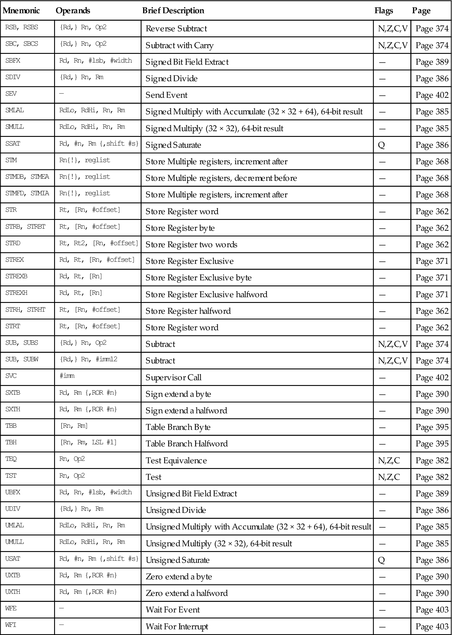
ASR
Arithmetic Shift Right by n bits moves the left-hand 32–n bits of the register Rm to the right by n places, into the right-hand 32–n bits of the result. And it copies the original bit[31] of the register into the left-hand n bits of the result; see Figure A.1.
You can use the ASR #n operation to divide the value in the register Rm by 2n, with the result being rounded toward negative-infinity.
When the instruction is ASRS or when ASR #n is used in Operand2 with the instructions MOVS, MVNS, ANDS, ORRS, ORNS, EORS, BICS, TEQ, or TST, the carry flag is updated to the last bit shifted out, bit[n–1], of the register Rm.
Note
LSR
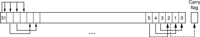
Logical Shift Right by n bits moves the left-hand 32–n bits of the register Rm, to the right by n places, into the right-hand 32–n bits of the result. And it sets the left-hand n bits of the result to 0. See Figure A.2.
You can use the LSR #n operation to divide the value in the register Rm by 2n, if the value is regarded as an unsigned integer.
When the instruction is LSRS or when LSR #n is used in Operand2 with the instructions MOVS, MVNS, ANDS, ORRS, ORNS, EORS, BICS, TEQ or TST, the carry flag is updated to the last bit shifted out, bit[n–1], of the register Rm.
Note
LSL
Logical Shift Left by n bits moves the right-hand 32–n bits of the register Rm, to the left by n places, into the left-hand 32–n bits of the result. And it sets the right-hand n bits of the result to 0. See Figure A.3.
You can use the LSL #n operation to multiply the value in the register Rm by 2n, if the value is regarded as an unsigned integer or a two's complement signed integer. Overflow can occur without warning.
When the instruction is LSLS or when LSL #n, with nonzero n, is used in Operand2 with the instructions MOVS, MVNS, ANDS, ORRS, ORNS, EORS, BICS, TEQ, or TST, the carry flag is updated to the last bit shifted out, bit[32-n], of the register Rm. These instructions do not affect the carry flag when used with LSL #0.
Note
ROR
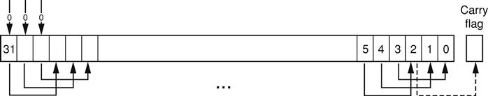
Rotate Right by n bits moves the left-hand 32–n bits of the register Rm, to the right by n places, into the right-hand 32–n bits of the result. And it moves the right-hand n bits of the register into the left-hand n bits of the result. See Figure A.4.

When the instruction is RORS or when ROR #n is used in Operand2 with the instructions MOVS, MVNS, ANDS, ORRS, ORNS, EORS, BICS, TEQ, or TST, the carry flag is updated to the last bit rotation, bit[n-1], of the register Rm.
Note
RRX
Rotate Right with Extend moves the bits of the register Rm to the right by 1 bit. And it copies the carry flag into bit[31] of the result; see Figure A.5.
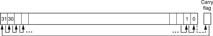
When the instruction is RRXS or when RRX is used in Operand2 with the instructions MOVS, MVNS, ANDS, ORRS, ORNS, EORS, BICS, TEQ, or TST, the carry flag is updated to bit[0] of the register Rm.
A.2.5 Address Alignment
An aligned access is an operation where a word-aligned address is used for a word, dual word, or multiple word access, or where a halfword-aligned address is used for a halfword access. Byte accesses are always aligned.
The Cortex-M3 processor supports unaligned access only for the following instructions:
All other load and store instructions generate a usage fault exception if they perform an unaligned access, and therefore, their accesses must be address aligned.
Unaligned accesses are usually slower than aligned accesses. In addition, some memory regions might not support unaligned accesses. Therefore, ARM recommends that programmers ensure that accesses are aligned. To trap accidental generation of unaligned accesses, use the UNALIGN_TRP bit in the Configuration and Control register to trigger usage fault exception for all unaligned accesses.
A.2.6 PC-Relative Expressions
A PC-relative expression or label is a symbol that represents the address of an instruction or literal data. It is represented in the instruction as the PC value plus or minus a numeric offset. The assembler calculates the required offset from the label and the address of the current instruction. If the offset is too big, the assembler produces an error.
Note
• For B, BL, CBNZ, and CBZ instructions, the value of the PC is the address of the current instruction plus 4 bytes.
• For most other instructions that use labels, the value of the PC is the address of the current instruction plus 4 bytes, with bit[1] of the result cleared to 0 to make it word-aligned.
• Your assembler might permit other syntaxes for PC-relative expressions, such as a label plus or minus a number, or an expression of the form [PC, #number].
A.2.7 Conditional Execution
Most data-processing instructions can optionally update the condition flags in the Application Program Status Register (APSR) according to the result of the operation. Some instructions update all flags, and some only update a subset. If a flag is not updated, the original value is preserved. See the instruction descriptions for the flags they affect.
You can execute an instruction conditionally, based on the condition flags set in another instruction, either immediately after the instruction that updated the flags or after any number of intervening instructions that have not updated the flags.
Conditional execution is available by using conditional branches or by adding condition code suffixes to instructions. See Table A.2 for a list of the suffixes to add to instructions to make them conditional instructions. The condition code suffix enables the processor to test a condition based on the flags. If the condition test of a conditional instruction fails, the instruction
Table A.2
| Suffix | Flags | Meaning |
| EQ | Z = 1 | Equal |
| NE | Z = 0 | Not equal |
| CS or HS | C = 1 | Higher or same, unsigned ≥ |
| CC or LO | C = 0 | Lower, unsigned < |
| MI | N = 1 | Negative |
| PL | N = 0 | Positive or zero |
| VS | V = 1 | Overflow |
| VC | V = 0 | No overflow |
| HI | C = 1 and Z = 0 | Higher, unsigned > |
| LS | C = 0 or Z = 1 | Lower or same, unsigned ≤ |
| GE | N = V | Greater than or equal, signed ≥ |
| LT | N != V | Less than, signed < |
| GT | Z = 0 and N = V | Greater than, signed > |
| LE | Z = 1 and N != V | Less than or equal, signed ≤ |
| AL | Can have any value | Always; default when no suffix is specified |
Conditional instructions, except for conditional branches, must be inside an If-Then instruction block. See “IT” section on page 393 for more information and restrictions when using the IT instruction. Depending on the vendor, the assembler might automatically insert an IT instruction if you have conditional instructions outside the IT block.
Use the CBZ and CBNZ instructions to compare the value of a register against zero and branch on the result.
This section describes
The Condition Flags
The APSR contains the following condition flags:
N Set to 1 when the result of the operation was negative, cleared to 0 otherwise.
Z Set to 1 when the result of the operation was zero, cleared to 0 otherwise.
C Set to 1 when the operation resulted in a carry, cleared to 0 otherwise.
V Set to 1 when the operation caused overflow, cleared to 0 otherwise.
A carry occurs
• If the result of an addition is greater than or equal to 232
• If the result of a subtraction is positive or zero
• As the result of an inline barrel shifter operation in a move or logical instruction.
Overflow occurs when the sign of the result, in bit[31], does not match the sign of the result had the operation been performed at infinite precision, for example:
• if adding two negative values results in a positive value
• if adding two positive values results in a negative value
• if subtracting a positive value from a negative value generates a positive value
• if subtracting a negative value from a positive value generates a negative value
The Compare operations are identical to subtracting, for CMP, or adding, for CMN, except that the result is discarded. See the instruction descriptions for more information.
Note
Most instructions update the status flags only if the S suffix is specified; see the instruction descriptions for more information.
Condition Code Suffixes
The instructions that can be conditional have an optional condition code, shown in syntax descriptions as {cond}. Conditional execution requires a preceding IT instruction. An instruction with a condition code is only executed if the condition code flags in the APSR meet the specified condition. Table A.2 shows the condition codes to use.
You can use conditional execution with the IT instruction to reduce the number of branch instructions in code. Table A.2 also shows the relationship between condition code suffixes and the N, Z, C, and V flags.
Example A.1 shows the use of a conditional instruction to find the absolute value of a number. R0 = ABS(R1).
Example A.1
| MOVS | R0, R1 | ; R0 = R1, setting flags |
| IT | MI | ; IT - Skip next instruction if value 0 or positive |
| RSBMI | R0, R1, #0 | ; If negative, R0 = –R1 |
Example A.2 shows the use of conditional instructions to update the value of R4 if the signed values R0 is greater than R1 and R2 is greater than R3.
A.2.8 Instruction Width Selection
There are many instructions that can generate either a 16-bit encoding or a 32-bit encoding depending on the operands and destination register specified. For some of these instructions, you can force a specific instruction size by using an instruction width suffix. The .W suffix forces a 32-bit instruction encoding. The .N suffix forces a 16-bit instruction encoding.
If you specify an instruction width suffix and the assembler cannot generate an instruction encoding of the requested width, it generates an error.
Note
In some cases, it might be necessary to specify the .W suffix, for example, if the operand is the label of an instruction or literal data, as in the case of branch instructions. This is because the assembler might not automatically generate the right size encoding.
To use an instruction width suffix, place it immediately after the instruction mnemonic and condition code, if any. Example A.3 shows instructions with the instruction width suffix.
A.3 Memory Access Instructions
Table A.3 shows the memory access instructions.
Table A.3
| Mnemonic | Brief Description | See |
| ADR | Generate PC-relative address | ADR on page 362 |
| CLREX | Clear Exclusive | CLREX on page 372 |
| LDM{mode} | Load Multiple registers | LDM and STM on page 368 |
| LDR{type} | Load Register using immediate offset | LDR and STR, Immediate Offset on page 362 |
| LDR{type} | Load Register using register offset | LDR and STR, Register Offset on page 365 |
| LDR{type}T | Load Register with unprivileged access | LDR and STR, Unprivileged on page 366 |
| LDR | Load Register using PC-relative address | LDR, PC-Relative on page 367 |
| LDREX{type} | Load Register Exclusive | LDREX and STREX on page 371 |
| POP | Pop registers from stack | PUSH and POP on page 370 |
| PUSH | Push registers onto stack | PUSH and POP on page 370 |
| STM{mode} | Store Multiple registers | LDM and STM on page 368 |
| STR{type} | Store Register using immediate offset | LDR and STR, Immediate Offset on page 362 |
| STR{type} | Store Register using register offset | LDR and STR, Register Offset on page 365 |
| STR{type}T | Store Register with unprivileged access | LDR and STR, Unprivileged on page 366 |
| STREX{type} | Store Register Exclusive | LDREX and STREX on page 371 |
A.3.1 ADR
Generate PC-relative address.
Syntax
ADR{cond} Rd, labelwhere
Operation
ADR generates an address by adding an immediate value to the PC and writes the result to the destination register.
ADR facilitates the generation of position-independent code because the address is PC-relative. If you use ADR to generate a target address for a BX or BLX instruction, you must ensure that bit[0] of the address you generate is set to 1 for correct execution.
Values of label must be within the range of −4095 to +4095 from the address in the PC.
Note
You might have to use the .W suffix to get the maximum offset range or to generate addresses that are not word-aligned; see “Instruction Width Selection” section on page 360.
Restrictions
Rd must not be SP and must not be PC.
Condition Flags
This instruction does not change the flags.
Examples
ADR R1, TextMessage ; Write address value of a location labelled as ; TextMessage to R1A.3.2 LDR and STR, Immediate Offset
Load and Store with immediate offset, preindexed immediate offset or postindexed immediate offset.
Syntax
op{type}{cond} Rt, [Rn {, #offset}] ; immediate offsetop{type}{cond} Rt, [Rn, #offset]! ; pre-indexedop{type}{cond} Rt, [Rn], #offset ; post-indexedopD{cond} Rt, Rt2, [Rn {, #offset}] ; immediate offset, two wordsopD{cond} Rt, Rt2, [Rn, #offset]! ; pre-indexed, two wordsopD{cond} Rt, Rt2, [Rn], #offset ; post-indexed, two wordswhere
Op is one of the following:
LDR Load Register
STR Store Register
Type is one of the following:
B Unsigned byte, zero extends to 32 bits on loads
SB Signed byte, sign extends to 32 bits (LDR only)
H Unsigned halfword, zero extends to 32 bits on loads
SH Signed halfword, sign extends to 32 bits (LDR only)
- Omit, for word
cond is an optional condition code; see “Conditional Execution” section on page 358.
Rt is the register to load or store.
Rn is the register on which the memory address is based.
Offset is an offset from Rn. If offset is omitted, the address is the contents of Rn.
Rt2 is the additional register to load or store for two-word operations.
Operation
LDR instructions load one or two registers with a value from memory. STR instructions store one or two register values to memory.
Load and store instructions with immediate offset can use the following addressing modes.
Offset Addressing
The offset value is added to or subtracted from the address obtained from the register Rn. The result is used as the address for the memory access. The register Rn is unaltered. The assembly language syntax for this mode is
[Rn, #offset]Preindexed Addressing
The offset value is added to or subtracted from the address obtained from the register Rn. The result is used as the address for the memory access and written back into the register Rn. The assembly language syntax for this mode is
[Rn, #offset]!Postindexed Addressing
The address obtained from the register Rn is used as the address for the memory access. The offset value is added to or subtracted from the address and written back into the register Rn. The assembly language syntax for this mode is
[Rn], #offsetThe value to load or store can be a byte, halfword, word, or two words. Bytes and halfwords can either be signed or be unsigned; see “Address Alignment” section on page 357.
Table A.4 shows the ranges of offset for immediate, preindexed, and postindexed forms.

Restrictions
• Rt can be SP or PC for word loads only.
• Rt must be different from Rt2 for two-word loads.
• Rn must be different from Rt and Rt2 in the preindexed or postindexed forms.
Condition Flags
These instructions do not change the flags.
Examples
LDR R8, [R10] ; Loads R8 from the address in R10.LDRNE R2, [R5, #960]! ; Loads (conditionally) R2 from a word ; 960 bytes above the address in R5, and ; increments R5 by 960.STR R2, [R9,#const-struc] ; const-struc is an expression evaluating ; to a constant in the range 0–4095.STRH R3, [R4], #4 ; Store R3 as halfword data into address in ; R4, then increment R4 by 4LDRD R8, R9, [R3, #0x20] ; Load R8 from a word 32 bytes above the ; address in R3, and load R9 from a word 36 ; bytes above the address in R3STRD R0, R1, [R8], #–16 ; Store R0 to address in R8, and store R1 to ; a word 4 bytes above the address in R8, ; and then decrement R8 by 16.A.3.3 LDR and STR, Register Offset
Load and Store with register offset.
Syntax
op{type}{cond} Rt, [Rn, Rm {, LSL #n}]where
op is one of the following:
LDR Load Register
STR Store Register
Type is one of the following:
B Unsigned byte, zero extends to 32 bits on loads
SB Signed byte, sign extends to 32 bits (LDR only)
H Unsigned halfword, zero extends to 32 bits on loads
SH Signed halfword, sign extends to 32 bits (LDR only)
- Omit, for word
Cond is an optional condition code; see “Conditional Execution” section on page 358.
Rt is the register to load or store.
Rn is the register on which the memory address is based.
Rm is a register containing a value to be used as the offset.
Operation
LDR instructions load a register with a value from memory.
STR instructions store a register value into memory.
The memory address to load from or store to is at an offset from the register Rn. The offset is specified by the register Rm and can be shifted left by up to 3 bits using LSL.
The value to load or store can be a byte, halfword, or word. For load instructions, bytes and halfwords can either be signed or be unsigned; see “Address Alignment” section on page 357.
Restrictions
Condition Flags
These instructions do not change the flags.
Examples
STR R0, [R5, R1] ; Store value of R0 into an address equal to ; sum of R5 and R1LDRSB R0, [R5, R1, LSL #1] ; Read byte value from an address equal to ; sum of R5 and two times R1, sign extended it ; to a word value and put it in R0STR R0, [R1, R2, LSL #2] ; Stores R0 to an address equal to sum of R1 ; and four times R2A.3.4 LDR and STR, Unprivileged
Load and Store with unprivileged access.
Syntax
op{type}T{cond} Rt, [Rn {, #offset}] ; immediate offsetwhere
op is one of the following:
LDR Load Register
STR Store Register
type is one of the following:
B Unsigned byte, zero extends to 32 bits on loads
SB Signed byte, sign extends to 32 bits (LDR only)
H Unsigned halfword, zero extends to 32 bits on loads
SH Signed halfword, sign extends to 32 bits (LDR only)
- Omit, for word
cond is an optional condition code; see “Conditional Execution” section on page 358.
Rt is the register to load or store.
Rn is the register on which the memory address is based.
Offset is an offset from Rn and can be 0–255. If offset is omitted, the address is the value in Rn.
Operation
These load and store instructions perform the same function as the memory access instructions with immediate offset; see “LDR and STR, Immediate Offset” section on page 362. The difference is that these instructions have only unprivileged access even when used in privileged software.
When used in unprivileged software, these instructions behave exactly the same way as normal memory access instructions with immediate offset.
Restrictions
Condition Flags
These instructions do not change the flags.
Examples
STRBTEQ R4, [R7] ; Conditionally store least significant byte in ; R4 to an address in R7, with unprivileged accessLDRHT R2, [R2, #8] ; Load halfword value from an address equal to ; sum of R2 and 8 into R2, with unprivileged accessA.3.5 LDR, PC-Relative
Load register from memory.
Syntax
LDR{type}{cond} Rt, labelLDRD{cond} Rt, Rt2, label ; Load two wordswhere
type is one of the following:
B Unsigned byte, zero extends to 32 bits
SB Signed byte, sign extends to 32 bits
H Unsigned halfword, zero extends to 32 bits
SH Signed halfword, sign extends to 32 bits
- Omit, for word
cond is an optional condition code; see “Conditional Execution” section on page 358.
Rt is the register to load or store.
Rt2 is the second register to load or store.
label is a PC-relative expression; see “PC-Relative Expressions” section on page 358.
Operation
LDR loads a register with a value from a PC-relative memory address. The memory address is specified by a label or by an offset from the PC.
The value to load or store can be a byte, halfword, or word. For load instructions, bytes and halfwords can either be signed or be unsigned; see “Address Alignment” section on page 357.
label must be within a limited range of the current instruction. Table A.5 shows the possible offsets between label and PC.
Note
You might have to use the .W suffix to get the maximum offset range; see “Instruction Width Selection” section on page 360.
Restrictions
Condition Flags
These instructions do not change the flags.
Examples
LDR R0, LookUpTable ; Load R0 with a word of data from an address ; labelled as LookUpTableLDRSB R7, localdata ; Load a byte value from an address labelled ; as localdata, sign extend it to a word ; value, and put it in R7A.3.6 LDM and STM
Load and Store Multiple registers.
Syntax
op{addr_mode}{cond} Rn{!}, reglistwhere
op is one of the following:
LDM Load Multiple registers
STM Store Multiple registers
addr_mode is any one of the following:
IA Increment address After each access; this is the default
DB Decrement address Before each access
Cond is an optional condition code; see “Conditional Execution” section on page 358.
Rn is the register on which the memory addresses are based.
! is an optional writeback suffix. If ! is present, the final address, that is loaded from or stored to, is written back into Rn.
reglist is a list of one or more registers to be loaded or stored, enclosed in braces. It can contain register ranges. It must be comma separated if it contains more than one register or register range; see “Examples” section on page 370.
• LDM and LDMFD are synonyms for LDMIA. LDMFD refers to its use for popping data from Full Descending stacks.
• LDMEA is a synonym for LDMDB and refers to its use for popping data from Empty Ascending stacks.
• STM and STMEA are synonyms for STMIA. STMEA refers to its use for pushing data onto Empty Ascending stacks.
• STMFD is synonym for STMDB and refers to its use for pushing data onto Full Descending stacks
Operation
LDM instructions load the registers in reglist with word values from memory addresses based on Rn. STM instructions store the word values in the registers in reglist to memory addresses based on Rn.
For LDM, LDMIA, LDMFD, STM, STMIA, and STMEA, the memory addresses used for the accesses are at 4-byte intervals ranging from Rn to Rn + 4 * (n−1), where n is the number of registers in reglist. The accesses happen in order of increasing register numbers, with the lowest numbered register using the lowest memory address and the highest number register using the highest memory address. If the writeback suffix is specified, the value of Rn + 4 * (n–1) is written back to Rn.
For LDMDB, LDMEA, STMDB, and STMFD, the memory addresses used for the accesses are at 4-byte intervals ranging from Rn to Rn – 4 * (n–1), where n is the number of registers in reglist. The accesses happen in order of decreasing register numbers, with the highest numbered register using the highest memory address and the lowest number register using the lowest memory address. If the writeback suffix is specified, the value of Rn – 4 * (n–1) is written back to Rn.
The PUSH and POP instructions can be expressed in this form; see “PUSH and POP” section on page 370 for details.
Restrictions
Condition Flags
These instructions do not change the flags.
Examples
LDM R8,{R0,R2,R9} ; LDMIA is a synonym for LDMSTMDB R1!,{R3–R6,R11,R12}Incorrect Examples
STM R5!,{R5,R4,R9} ; Value stored for R5 is unpredictableLDM R2, {} ; There must be at least one register in the listA.3.7 PUSH and POP
Push registers onto and pop registers off a full-descending stack.
Syntax
PUSH{cond} reglistPOP{cond} reglistwhere
cond is an optional condition code; see “Conditional Execution” section on page 358.
Reglist is a nonempty list of registers, enclosed in braces. It can contain register ranges. It must be comma separated if it contains more than one register or register range.
PUSH and POP are synonyms for STMDB and LDM (or LDMIA) with the memory addresses for the access based on SP and with the final address for the access written back to the SP. PUSH and POP are the preferred mnemonics in these cases.
Operation
PUSH stores registers on the stack, with the lowest numbered register using the lowest memory address and the highest numbered register using the highest memory address.
POP loads registers from the stack, with the lowest numbered register using the lowest memory address and the highest numbered register using the highest memory address.
PUSH uses the value in the SP register minus four as the highest memory address, POP uses the value in the SP register as the lowest memory address, implementing a full-descending stack. On completion, PUSH updates the SP register to point to the location of the lowest store value, POP updates the SP register to point to the location above the highest location loaded.
If a POP instruction includes PC in its reglist, a branch to this location is performed when the POP instruction has completed. Bit[0] of the value read for the PC is used to update the APSR T-bit. This bit must be 1 to ensure correct operation.
See LDM and STM on page 368 for more information.
Restrictions
Condition Flags
These instructions do not change the flags.
Examples
PUSH {R0,R4-R7} ; Push R0, R4, R5, R6, R7 onto the stackPUSH {R2,LR} ; Push R2 and the link-register onto the stackPOP {R0,R6,PC} ; Pop R0, R6 and PC from the stack, then branch to the new PC.A.3.8 LDREX and STREX
Load and Store Register Exclusive.
Syntax
LDREX{cond} Rt, [Rn {, #offset}]STREX{cond} Rd, Rt, [Rn {, #offset}]LDREXB{cond} Rt, [Rn]STREXB{cond} Rd, Rt, [Rn]LDREXH{cond} Rt, [Rn]STREXH{cond} Rd, Rt, [Rn]where
cond is an optional condition code; see “Conditional Execution” section on page 358.
Rd is the destination register for the returned status.
Rt is the register to load or store.
Rn is the register on which the memory address is based.
offset is an optional offset applied to the value in Rn. If offset is omitted, the address is the value in Rn.
Operation
LDREX, LDREXB, and LDREXH load a word, byte, and halfword, respectively, from a memory address.
STREX, STREXB, and STREXH attempt to store a word, byte, and halfword, respectively, to a memory address. The address used in any store-exclusive instruction must be the same as the address in the most recently executed load-exclusive instruction. The values stored by the store-exclusive instruction must also have the same data size as the value loaded by the preceding load-exclusive instruction. This means software must always use a load-exclusive instruction and a matching store-exclusive instruction to perform a synchronization operation.
If a store-exclusive instruction performs the store, it writes 0 to its destination register. If it does not perform the store, it writes 1 to its destination register. If the store-exclusive instruction writes 0 to the destination register, it is guaranteed that no other process in the system has accessed the memory location between the load-exclusive and store-exclusive instructions.
For reasons of performance, keep the number of instructions between corresponding load-exclusive and store-exclusive instruction to a minimum.
Note
The result of executing a store-exclusive instruction to an address that is different from that used in the preceding load-exclusive instruction is unpredictable.
Restrictions
Condition Flags
These instructions do not change the flags.
Examples
MOV R1, #0x1 ; Initialize the 'lock taken' value tryLDREX R0, [LockAddr] ; Load the lock valueCMP R0, #0 ; Is the lock free?ITT EQ ; IT instruction for STREXEQ and CMPEQSTREXEQ R0, R1, [LockAddr] ; Try and claim the lockCMPEQ R0, #0 ; Did this succeed?BNE try ; No – try again.... ; Yes – we have the lockA.3.9 CLREX
Clear Exclusive.
Syntax
CLREX{cond}where
cond is an optional condition code; see “Conditional Execution” section on page 358.
Operation
Use CLREX to make the next STREX, STREXB, or STREXH instructions write 1 to its destination register and fail to perform the store. It is useful in exception handler code to force the failure of the store exclusive if the exception occurs between a load-exclusive instruction and the matching store-exclusive instruction in a synchronization operation.
Condition Flags
These instructions do not change the flags.
Examples
CLREXA.4 General Data-Processing Instructions
Table A.6 shows the data-processing instructions.
Table A.6
| Mnemonic | Brief Description | See |
| ADC | Add with Carry | ADD, ADC, SUB, SBC, and RSB on page 374 |
| ADD | Add | ADD, ADC, SUB, SBC, and RSB on page 374 |
| ADDW | Add | ADD, ADC, SUB, SBC, and RSB on page 374 |
| AND | Logical AND | AND, ORR, EOR, BIC, and ORN on page 376 |
| ASR | Arithmetic Shift Right | ASR, LSL, LSR, ROR, and RRX on page 377 |
| BIC | Bit Clear | AND, ORR, EOR, BIC, and ORN on page 376 |
| CLZ | Count leading zeros | CLZ on page 378 |
| CMN | Compare Negative | CMP and CMN on page 378 |
| CMP | Compare | CMP and CMN on page 378 |
| EOR | Exclusive OR | AND, ORR, EOR, BIC, and ORN on page 376 |
| LSL | Logical Shift Left | ASR, LSL, LSR, ROR, and RRX on page 377 |
| LSR | Logical Shift Right | ASR, LSL, LSR, ROR, and RRX on page 377 |
| MOV | Move | MOV and MVN on page 379 |
| MOVT | Move Top | MOVT on page 381 |
| MOVW | Move 16-bit constant | MOV and MVN on page 379 |
| MVN | Move NOT | MOV and MVN on page 379 |
| ORN | Logical OR NOT | AND, ORR, EOR, BIC, and ORN on page 376 |
| ORR | Logical OR | AND, ORR, EOR, BIC, and ORN on page 376 |
| RBIT | Reverse Bits | REV, REV16, REVSH, and RBIT on page 381 |
| REV | Reverse byte order in a word | REV, REV16, REVSH, and RBIT on page 381 |
| REV16 | Reverse byte order in each halfword | REV, REV16, REVSH, and RBIT on page 381 |
| REVSH | Reverse byte order in bottom halfword and sign extend | REV, REV16, REVSH, and RBIT on page 381 |
| ROR | Rotate Right | ASR, LSL, LSR, ROR, and RRX on page 377 |
| RRX | Rotate Right with Extend | ASR, LSL, LSR, ROR, and RRX on page 377 |
| RSB | Reverse Subtract | ADD, ADC, SUB, SBC, and RSB on page 374 |
| SBC | Subtract with Carry | ADD, ADC, SUB, SBC, and RSB on page 374 |
| SUB | Subtract | ADD, ADC, SUB, SBC, and RSB on page 374 |
| SUBW | Subtract | ADD, ADC, SUB, SBC, and RSB on page 374 |
| TEQ | Test Equivalence | TST and TEQ on page 382 |
| TST | Test | TST and TEQ on page 382 |
A.4.1 ADD, ADC, SUB, SBC, and RSB
Add, Add with Carry, Subtract, Subtract with Carry, and Reverse Subtract.
Syntax
op{S}{cond} {Rd,} Rn, Operand2op{cond} {Rd,} Rn, #imm12 ; ADD and SUB onlywhere
op is one of the following:
ADD Add
ADC Add with Carry
SUB Subtract
SBC Subtract with Carry
RSB Reverse Subtract
S is an optional suffix. If S is specified, the condition code flags are updated on the result of the operation; see “Conditional Execution” section on page 358.
Cond is an optional condition code; see “Conditional Execution” section on page 358.
Rd is the destination register. If Rd is omitted, the destination register is Rn.
Rn is the register holding the first operand.
Operand2 is a flexible second operand; see “Flexible Second Operand” section on page 353 for details of the options.
Operation
The ADD instruction adds the value of Operand2 or imm12 to the value in Rn. The ADC instruction adds the values in Rn and Operand2, together with the carry flag.
The SUB instruction subtracts the value of Operand2 or imm12 from the value in Rn. The SBC instruction subtracts the value of Operand2 from the value in Rn. If the carry flag is clear, the result is reduced by one.
The RSB instruction subtracts the value in Rn from the value of Operand2. This is useful because of the wide range of options for Operand2.
Use ADC and SBC to synthesize multiword arithmetic; see “Multiword Arithmetic Examples” section on page 376; see also “ADR” section on page 362.
Note
ADDW is equivalent to the ADD syntax that uses the imm12 operand. SUBW is equivalent to the SUB syntax that uses the imm12 operand.
Restrictions
• Operand2 must not be SP and must not be PC.
• Rd can be SP only in ADD and SUB and only with the additional restrictions.
• Any shift in Operand2 must be limited to a maximum of 3 bits using LSL.
• Rn can be SP only in ADD and SUB.
• Rd can be PC only in the ADD{cond} PC, PC, Rm instruction where:
• You must not specify the S suffix.
• Rm must not be PC and must not be SP.
• If the instruction is conditional, it must be the last instruction in the IT block.
• With the exception of the ADD{cond} PC, PC, Rm instruction, Rn can be PC only in ADD and SUB, and only with the additional restrictions:
• You must not specify the S suffix.
• The second operand must be a constant in the range 0–4095.
Note
• When using the PC for an addition or a subtraction, bits[1:0] of the PC are rounded to b00 before performing the calculation, making the base address for the calculation word-aligned.
• If you want to generate the address of an instruction, you have to adjust the constant based on the value of the PC. ARM recommends that you use the ADR instruction instead of ADD or SUB with Rn equal to the PC, because your assembler automatically calculates the correct constant for the ADR instruction.
Condition Flags
If S is specified, these instructions update the N, Z, C, and V flags according to the result.
Examples
ADD R2, R1, R3SUBS R8, R6, #240 ; Sets the flags on the resultRSB R4, R4, #1280 ; Subtracts contents of R4 from 1280ADCHI R11, R0, R3 ; Only executed if C flag set and Z ; flag clearMultiword Arithmetic Examples
Example A.4 shows two instructions that add a 64-bit integer contained in R2 and R3 to another 64-bit integer contained in R0 and R1 and place the result in R4 and R5.
Example A.4
| ADDS | R4, R0, R2 | ; add the least significant words |
| ADC | R5, R1, R3 | ; add the most significant words with carry |
Multiword values do not have to use consecutive registers. Example A.5 shows instructions that subtract a 96-bit integer contained in R9, R1, and R11 from another contained in R6, R2, and R8. The example stores the result in R6, R9, and R2.
A.4.2 AND, ORR, EOR, BIC, and ORN
Logical AND, OR, Exclusive OR, Bit Clear, and OR NOT.
Syntax
op{S}{cond} {Rd,} Rn, Operand2where
op is one of the following:
AND Logical AND
ORR Logical OR or bit set
EOR Logical Exclusive OR
BIC Logical AND NOT or Bit Clear
ORN Logical OR NOT
S is an optional suffix. If S is specified, the condition code flags are updated on the result of the operation; see “Conditional Execution” section on page 358.
Cond is an optional condition code; see “Conditional Execution” section on page 358.
Rd is the destination register.
Rn is the register holding the first operand.
Operand2 is a flexible second operand; see “Flexible Second Operand” section on page 353 for details of the options.
Operation
The AND, EOR, and ORR instructions perform bitwise AND, Exclusive OR, and OR operations on the values in Rn and Operand2.
The BIC instruction performs an AND operation on the bits in Rn with the complements of the corresponding bits in the value of Operand2.
The ORN instruction performs an OR operation on the bits in Rn with the complements of the corresponding bits in the value of Operand2.
Restrictions
Do not use SP and do not use PC.
Condition Flags
If S is specified, these instructions
Examples
AND R9, R2, #0xFF00ORREQ R2, R0, R5ANDS R9, R8, #0x19EORS R7, R11, #0x18181818BIC R0, R1, #0xabORNS R7, R11, R14, ROR #4ORNS R7, R11, R14, ASR #32A.4.3 ASR, LSL, LSR, ROR, and RRX
Arithmetic Shift Right, Logical Shift Left, Logical Shift Right, Rotate Right, and Rotate Right with Extend.
Syntax
op{S}{cond} Rd, Rm, Rsop{S}{cond} Rd, Rm, #nRRX{S}{cond} Rd, Rmwhere
op is one of the following:
ASR Arithmetic Shift Right
LSL Logical Shift Left
LSR Logical Shift Right
ROR Rotate Right
S is an optional suffix. If S is specified, the condition code flags are updated on the result of the operation; see “Conditional Execution” section on page 358.
Rd is the destination register.
Rm is the register holding the value to be shifted.
Rs is the register holding the shift length to apply to the value in Rm. Only the least significant byte is used and can be in the range 0–255.
n is the shift length. The range of shift length depends on the instruction:
ASR Shift length from 1 to 32
LSL Shift length from 0 to 31
LSR Shift length from 1 to 32
ROR Shift length from 1 to 31
Note
MOVS Rd, Rm is the preferred syntax for LSLS Rd, Rm, #0.
Operation
ASR, LSL, LSR, and ROR move the bits in the register Rm to the left or right by the number of places specified by constant n or register Rs. RRX moves the bits in register Rm to the right by 1.
In all these instructions, the result is written to Rd, but the value in register Rm remains unchanged. For details on what result is generated by the different instructions, see “Shift Operations” section on page 354.
Restrictions
Do not use SP and do not use PC.
Condition Flags
Examples
ASR R7, R8, #9 ; Arithmetic shift right by 9 bitsLSLS R1, R2, #3 ; Logical shift left by 3 bits with flag updateLSR R4, R5, #6 ; Logical shift right by 6 bitsROR R4, R5, R6 ; Rotate right by the value in the bottom byte of R6RRX R4, R5 ; Rotate right with extendA.4.4 CLZ
Count Leading Zeros.
Syntax
CLZ{cond} Rd, Rmwhere
Operation
The CLZ instruction counts the number of leading zeros in the value in Rm and returns the result in Rd. The result value is 32 if no bits are set in the source register and 0 if bit[31] is set.
Restrictions
Do not use SP and do not use PC.
Condition Flags
This instruction does not change the flags.
Examples
CLZ R4,R9CLZNE R2,R3A.4.5 CMP and CMN
Compare and Compare Negative.
Syntax
CMP{cond} Rn, Operand2CMN{cond} Rn, Operand2where
Operation
These instructions compare the value in a register with Operand2. They update the condition flags on the result but do not write the result to a register.
The CMP instruction subtracts the value of Operand2 from the value in Rn. This is the same as a SUBS instruction, except that the result is discarded.
The CMN instruction adds the value of Operand2 to the value in Rn. This is the same as an ADDS instruction, except that the result is discarded.
Restrictions
Condition Flags
These instructions update the N, Z, C, and V flags according to the result.
Examples
CMP R2, R9CMN R0, #6400CMPGT SP, R7, LSL #2A.4.6 MOV and MVN
Move and Move NOT.
Syntax
MOV{S}{cond} Rd, Operand02MOV{cond} Rd, #imm16MVN{S}{cond} Rd, Operand2where
S is an optional suffix. If S is specified, the condition code flags are updated on the result of the operation; see “Conditional Execution” section on page 358.
cond is an optional condition code; see “Conditional Execution” section on page 358.
Rd is the destination register.
Operand2 is a flexible second operand; see “Flexible Second Operand” section on page 353 for details of the options.
Operation
The MOV instruction copies the value of Operand2 into Rd. When Operand2 in a MOV instruction is a register with a shift other than LSL #0, the preferred syntax is the corresponding shift instruction:
• ASR{S}{cond} Rd, Rm, #n is the preferred syntax for MOV{S}{cond} Rd, Rm, ASR #n.
• LSL{S}{cond} Rd, Rm, #n is the preferred syntax for MOV{S}{cond} Rd, Rm, LSL #n if n != 0.
• LSR{S}{cond} Rd, Rm, #n is the preferred syntax for MOV{S}{cond} Rd, Rm, LSR #n.
• ROR{S}{cond} Rd, Rm, #n is the preferred syntax for MOV{S}{cond} Rd, Rm, ROR #n.
• RRX{S}{cond} Rd, Rm is the preferred syntax for MOV{S}{cond} Rd, Rm, RRX.
Also, the MOV instruction permits additional forms of Operand2 as synonyms for shift instructions:
• MOV{S}{cond} Rd, Rm, ASR Rs is a synonym for ASR{S}{cond} Rd, Rm, Rs.
• MOV{S}{cond} Rd, Rm, LSL Rs is a synonym for LSL{S}{cond} Rd, Rm, Rs.
• MOV{S}{cond} Rd, Rm, LSR Rs is a synonym for LSR{S}{cond} Rd, Rm, Rs.
• MOV{S}{cond} Rd, Rm, ROR Rs is a synonym for ROR{S}{cond} Rd, Rm, Rs.
See ASR, LSL, LSR, ROR, and RRX on page 377.
The MVN instruction takes the value of Operand2, performs a bitwise logical NOT operation on the value, and places the result into Rd.
Note
The MOVW instruction provides the same function as MOV but is restricted to using the imm16 operand.
Restrictions
You can use SP and PC only in the MOV instruction, with the following restrictions:
Note
Though it is possible to use MOV as a branch instruction, ARM strongly recommends the use of a BX or BLX instruction to branch for software portability to the ARM instruction set.
Condition Flags
If S is specified, these instructions:
Example
| MOVS | R11, #0x000B | ; Write value of 0x000B to R11, flags get updated |
| MOV | R1, #0xFA05 | ; Write value of 0xFA05 to R1, flags are not updated |
| MOVS | R10, R12 | ; Write value in R12 to R10, flags get updated |
| MOV | R3, #23 | ; Write value of 23 to R3 |
| MOV | R8, SP | ; Write value of stack pointer to R8 |
| MVNS | R2, #0xF | ; Write value of 0xFFFFFFF0 (bitwise inverse of0xF) ; to the R2 and update flags |
A.4.7 MOVT
Move Top.
Syntax
MOVT{cond} Rd, #imm16where
Operation
MOVT writes a 16-bit immediate value, imm16, to the top halfword, Rd[31:16], of its destination register. The write does not affect Rd[15:0].
The MOV, MOVT instruction pair enables you to generate any 32-bit constant.
Restrictions
Rd must not be SP and must not be PC.
Condition Flags
This instruction does not change the flags.
Examples
MOVT R3, #0xF123 ; Write 0xF123 to upper halfword of R3, lower halfword ; and APSR are unchangedA.4.8 REV, REV16, REVSH, and RBIT
Reverse bytes and Reverse bits.
Syntax
op{cond} Rd, Rnwhere
op is any of the following:
REV Reverse byte order in a word
REV16 Reverse byte order in each halfword independently
REVSH Reverse byte order in the bottom halfword, and sign extends to 32 bits
RBIT Reverse the bit order in a 32-bit word
cond is an optional condition code; see “Conditional Execution” section on page 358.
Operation
Use these instructions to change endianness of data:
REV converts 32-bit big-endian data into little-endian data or 32-bit little-endian data into big-endian data.
REV16 converts 16-bit big-endian data into little-endian data or 16-bit little-endian data into big-endian data.
REVSH converts either:
16-bit signed big-endian data into 32-bit signed little-endian data
16-bit signed little-endian data into 32-bit signed big-endian data.
Restrictions
Do not use SP and do not use PC.
Condition Flags
These instructions do not change the flags.
Examples
| REV | R3, R7 | ; Reverse byte order of value in R7 and write it to R3 |
| REV16 | R0, R0 | ; Reverse byte order of each 16-bit halfword in R0 |
| REVSH | R0, R5 | ; Reverse Signed Halfword |
| REVHS | R3, R7 | ; Reverse with Higher or Same condition |
| RBIT | R7, R8 | ; Reverse bit order of value in R8 and write the result to R7 |
A.4.9 TST and TEQ
Test bits and Test Equivalence.
Syntax
TST{cond} Rn, Operand2TEQ{cond} Rn, Operand2where
Operation
These instructions test the value in a register against Operand2. They update the condition flags based on the result but do not write the result to a register.
The TST instruction performs a bitwise AND operation on the value in Rn and the value of Operand2. This is the same as the ANDS instruction, except that it discards the result.
To test whether a bit of Rn is 0 or 1, use the TST instruction with an Operand2 constant that has bit set to 1 and all other bits cleared to 0.
The TEQ instruction performs a bitwise Exclusive OR operation on the value in Rn and the value of Operand2. This is same as the EORS instruction, except that it discards the result.
Use the TEQ instruction to test if two values are equal without affecting the V or C flags.
TEQ is also useful for testing the sign of a value. After the comparison, the N flag is the logical Exclusive OR of the sign bits of the two operands.
Restrictions
Do not use SP and do not use PC.
Condition Flags
Examples
TST R0, #0x3F8 ; Perform bitwise AND of R0 value to 0x3F8, ; APSR is updated but result is discardedTEQEQ R10, R9 ; Conditionally test if value in R10 is equal to ; value in R9, APSR is updated but result is discardedA.5 Multiply and Divide Instructions
Table A.7 shows the multiply and divide instructions.
Table A.7
Multiply and Divide Instructions
| Mnemonic | Brief Description | See |
| MLA | Multiply with Accumulate, 32-bit result | MUL, MLA, and MLS on page 383 |
| MLS | Multiply and Subtract, 32-bit result | MUL, MLA, and MLS on page 383 |
| MUL | Multiply, 32-bit result | MUL, MLA, and MLS on page 383 |
| SDIV | Signed Divide | SDIV and UDIV on page 386 |
| SMLAL | Signed Multiply with Accumulate (32 × 32 + 64), 64-bit result | UMULL, UMLAL, SMULL, and SMLAL on page 385 |
| SMULL | Signed Multiply (32 × 32), 64-bit result | UMULL, UMLAL, SMULL, and SMLAL on page 385 |
| UDIV | Unsigned Divide | SDIV and UDIV on page 386 |
| UMLAL | Unsigned Multiply with Accumulate (32 × 32 + 64), 64-bit result | UMULL, UMLAL, SMULL, and SMLAL on page 385 |
| UMULL | Unsigned Multiply (32 × 32), 64-bit result | UMULL, UMLAL, SMULL, and SMLAL on page 385 |
A.5.1 MUL, MLA, and MLS
Multiply, Multiply with Accumulate, and Multiply with Subtract, using 32-bit operands and producing a 32-bit result.
Syntax
MUL{S}{cond} Rd, Rn, Rm ; MultiplyMLA{cond} Rd, Rn, Rm, Ra ; Multiply with accumulateMLS{cond} Rd, Rn, Rm, Ra ; Multiply with subtractwhere
cond is an optional condition code; see “Conditional Execution” section on page 358.
S is an optional suffix. If S is specified, the condition code flags are updated on the result of the operation; see “Conditional Execution” section on page 358.
Rd is the destination register. If Rd is omitted, the destination register is Rn.
Rn, Rm are registers holding the values to be multiplied.
Ra is a register holding the value to be added or subtracted from.
Operation
The MUL instruction multiplies the values from Rn and Rm and places the least significant 32 bits of the result in Rd.
The MLA instruction multiplies the values from Rn and Rm, adds the value from Ra, and places the least significant 32 bits of the result in Rd.
The MLS instruction multiplies the values from Rn and Rm, subtracts the product from the value from Ra, and places the least significant 32 bits of the result in Rd.
The results of these instructions do not depend on whether the operands are signed or unsigned.
Restrictions
In these instructions, do not use SP and do not use PC.
Condition Flags
Examples
| MUL | R10, R2, R5 | ; Multiply, R10 = R2 × R5 |
| MLA | R10, R2, R1, R5 | ; Multiply with accumulate, R10 = (R2 × R1) + R5 |
| MULS | R0, R2, R2 | ; Multiply with flag update, R0 = R2 × R2 |
| MULLT | R2, R3, R2 | ; Conditionally multiply, R2 = R3 × R2 |
| MLS | R4, R5, R6, R7 | ; Multiply with subtract, R4 = R7 – (R5 × R6) |
A.5.2 UMULL, UMLAL, SMULL, and SMLAL
Signed and Unsigned Long Multiply, with optional Accumulate, using 32-bit operands and producing a 64-bit result.
Syntax
op{cond} RdLo, RdHi, Rn, Rmwhere
op is one of the following:
UMULL Unsigned Long Multiply
UMLAL Unsigned Long Multiply, with Accumulate
SMULL Signed Long Multiply
SMLAL Signed Long Multiply, with Accumulate
Cond is an optional condition code; see “Conditional Execution” section on page 358.
RdHi, RdLo are the destination registers. For UMLAL and SMLAL, they also hold the accumulating value.
Operation
The UMULL instruction interprets the values from Rn and Rm as unsigned integers. It multiplies these integers and places the least significant 32 bits of the result in RdLo and the most significant 32 bits of the result in RdHi.
The UMLAL instruction interprets the values from Rn and Rm as unsigned integers. It multiplies these integers, adds the 64-bit result to the 64-bit unsigned integer contained in RdHi and RdLo, and writes the result back to RdHi and RdLo.
The SMULL instruction interprets the values from Rn and Rm as two's complement signed integers. It multiplies these integers and places the least significant 32 bits of the result in RdLo and the most significant 32 bits of the result in RdHi.
The SMLAL instruction interprets the values from Rn and Rm as two's complement signed integers. It multiplies these integers, adds the 64-bit result to the 64-bit signed integer contained in RdHi and RdLo, and writes the result back to RdHi and RdLo.
Restrictions
Condition Flags
These instructions do not affect the condition code flags.
Examples
UMULL R0, R4, R5, R6 ; Unsigned (R4,R0) = R5 × R6SMLAL R4, R5, R3, R8 ; Signed (R5,R4) = (R5,R4) + R3 × R8A.5.3 SDIV and UDIV
Signed Divide and Unsigned Divide.
Syntax
SDIV{cond} {Rd,} Rn, RmUDIV{cond} {Rd,} Rn, Rmwhere
Operation
SDIV performs a signed integer division of the value in Rn by the value in Rm. UDIV performs an unsigned integer division of the value in Rn by the value in Rm.
For both instructions, if the value in Rn is not divisible by the value in Rm, the result is rounded toward zero.
Restrictions
Do not use SP and do not use PC.
Condition Flags
These instructions do not change the flags.
Examples
SDIV R0, R2, R4 ; Signed divide, R0 = R2/R4UDIV R8, R8, R1 ; Unsigned divide, R8 = R8/R1A.6 Saturating Instructions
This section describes the saturating instructions: SSAT and USAT.
A.6.1 SSAT and USAT
Signed Saturate and Unsigned Saturate to any bit position, with optional shift before saturating.
Syntax
op{cond} Rd, #n, Rm {, shift #s}where
op is one of the following:
SSAT Saturates a signed value to a signed range
USAT Saturates a signed value to an unsigned range
cond is an optional condition code; see “Conditional Execution” section on page 358.
Rd is the destination register.
n specifies the bit position to saturate to:
n ranges from 1 to 32 for SSAT
n ranges from 0 to 31 for USAT
Rm is the register containing the value to saturate.
shift #s is an optional shift applied to Rm before saturating. It must be one of the following:
ASR #s where s is in the range 1–31
LSL #s where s is in the range 0–31
Operation
These instructions saturate to a signed or unsigned n-bit value.
The SSAT instruction applies the specified shift and then saturates to the signed range −2n−1 ≤ x ≤ 2n−1 − 1. The USAT instruction applies the specified shift and then saturates to the unsigned range 0 ≤ x ≤ 2n − 1.
For signed n-bit saturation using SSAT, this means that
• If the value to be saturated is less than −2n−1, the result returned is −2n−1.
• If the value to be saturated is greater than 2n −1 − 1, the result returned is 2n−1 − 1.
• Otherwise, the result returned is the same as the value to be saturated.
For unsigned n-bit saturation using USAT, this means that
• If the value to be saturated is less than 0, the result returned is 0.
• If the value to be saturated is greater than 2n − 1, the result returned is 2n − 1.
• Otherwise, the result returned is the same as the value to be saturated.
If the returned result is different from the value to be saturated, it is called saturation. If saturation occurs, the instruction sets the Q flag to 1 in the APSR. Otherwise, it leaves the Q flag unchanged. To clear the Q flag to 0, you must use the MSR instruction; see MSR on page 400.
To read the state of the Q flag, use the MRS instruction; see “MRS” section on page 400.
Restrictions
Do not use SP and do not use PC.
Condition Flags
These instructions do not affect the condition code flags.
If saturation occurs, these instructions set the Q flag to 1.
Examples
SSAT R7, #16, R7, LSL #4 ; Logical shift left value in R7 by 4, then; saturate it as a signed 16-bit value and
; write it back to R7
USATNE R0, #7, R5 ; Conditionally saturate value in R5 as an; unsigned 7 bit value and write it to R0
A.7 Bitfield Instructions
Table A.8 shows the instructions that operate on adjacent sets of bits in registers or bitfields.
Table A.8
Packing and Unpacking Instructions
| Mnemonic | Brief Description | See |
| BFC | Bit Field Clear | BFC and BFI on page 388 |
| BFI | Bit Field Insert | BFC and BFI on page 388 |
| SBFX | Signed Bit Field Extract | SBFX and UBFX on page 389 |
| SXTB | Sign extend a byte | SXT and UXT on page 390 |
| SXTH | Sign extend a halfword | SXT and UXT on page 390 |
| UBFX | Unsigned Bit Field Extract | SBFX and UBFX on page 389 |
| UXTB | Zero extend a byte | SXT and UXT on page 390 |
| UXTH | Zero extend a halfword | SXT and UXT on page 390 |
A.7.1 BFC and BFI
Bit Field Clear and Bit Field Insert.
Syntax
BFC{cond} Rd, #lsb, #widthBFI{cond} Rd, Rn, #lsb, #widthwhere
Operation
BFC clears a bitfield in a register. It clears width bits in Rd, starting at the low bit position lsb. Other bits in Rd are unchanged.
BFI copies a bitfield into one register from another register. It replaces width bits in Rd starting at the low bit position lsb, with width bits from Rn starting at bit[0]. Other bits in Rd are unchanged.
Restrictions
Do not use SP and do not use PC.
Condition Flags
These instructions do not affect the flags.
Examples
BFC R4, #8, #12 ; Clear bit 8 to bit 19 (12 bits) of R4 to 0BFI R9, R2, #8, #12 ; Replace bit 8 to bit 19 (12 bits) of R9 with ; bit 0 to bit 11 from R2A.7.2 SBFX and UBFX
Signed Bit Field Extract and Unsigned Bit Field Extract.
Syntax
SBFX{cond} Rd, Rn, #lsb, #widthUBFX{cond} Rd, Rn, #lsb, #widthwhere
Operation
SBFX extracts a bitfield from one register; sign extends it to 32 bits and writes the result to the destination register.
UBFX extracts a bitfield from one register; zero extends it to 32 bits and writes the result to the destination register.
Restrictions
Do not use SP and do not use PC.
Condition Flags
These instructions do not affect the flags.
Examples
SBFX R0, R1, #20, #4 ; Extract bit 20 to bit 23 (4 bits) from R1 and sign ; extend to 32 bits and then write the result to R0.UBFX R8, R11, #9, #10 ; Extract bit 9 to bit 18 (10 bits) from R11 and zero ; extend to 32 bits and then write the result to R8A.7.3 SXT and UXT
Sign extend and zero extend.
Syntax
SXT extend{cond} Rd, Rm {, ROR #n}UXT extend{cond} Rd, Rm {, ROR #n}where
extend is one of the following:
B extends an 8-bit value to a 32-bit value.
H extends a 16-bit value to a 32-bit value.
cond is an optional condition code; see “Conditional Execution” section on page 358.
Rd is the destination register.
Rm is the register holding the value to extend.
ROR #n is one of the following:
ROR #8 value from Rm is rotated right 8 bits.
ROR #16 value from Rm is rotated right 16 bits.
ROR #24 value from Rm is rotated right 24 bits.
If ROR #n is omitted, no rotation is performed.
Operation
Restrictions
Do not use SP and do not use PC.
Condition Flags
These instructions do not affect the flags.
Examples
SXTH R4, R6, ROR #16 ; Rotate R6 right by 16 bits, then obtain the lower ; halfword of the result and then sign extend to ; 32 bits and write the result to R4.UXTB R3, R10 ; Extract lowest byte of the value in R10 and zero ; extend it, and write the result to R3A.8 Branch and Control Instructions
Table A.9 shows the branch and control instructions.
Table A.9
Branch and Control Instructions
| Mnemonic | Brief Description | See |
| B | Branch | B, BL, BX, and BLX on page 391 |
| BL | Branch with Link | B, BL, BX, and BLX on page 391 |
| BLX | Branch indirect with Link | B, BL, BX, and BLX on page 391 |
| BX | Branch indirect | B, BL, BX, and BLX on page 391 |
| CBNZ | Compare and Branch if Nonzero | CBZ and CBNZ on page 393 |
| CBZ | Compare and Branch if zero | CBZ and CBNZ on page 393 |
| IT | If-Then | IT on page 393 |
| TBB | Table Branch Byte | TBB and TBH on page 395 |
| TBH | Table Branch Halfword | TBB and TBH on page 395 |
A.8.1 B, BL, BX, and BLX
Branch instructions.
Syntax
B{cond} labelBL{cond} labelBX{cond} RmBLX{cond} Rmwhere
BL is branch with link (immediate).
BX is branch indirect (register).
BLX is branch indirect with link (register).
cond is an optional condition code; see “Conditional Execution” section on page 358.
label is a PC-relative expression; see “PC-Relative Expressions” section on page 358.
Rm is a register that indicates an address to branch to. Bit[0] of the value in Rm must be 1, but the address to branch to is created by changing bit[0] to 0.
Operation
All these instructions cause a branch to label or to the address indicated in Rm. In addition:
• The BL and BLX instructions write the address of the next instruction to LR (the link register, R14).
• The BX and BLX instructions cause a usage fault exception if bit[0] of Rm is 0.
Bcond label is the only conditional instruction that can be either inside or outside an IT block. All other branch instructions must be conditional inside the IT block and must be unconditional outside the IT block; see “IT” section on page 393.
Table A.10 shows the ranges for the various branch instructions.
Note
You might have to use the .W suffix to get the maximum branch range; see “Instruction Width Selection” section on page 360.
Restrictions
Note
Bcond is the only conditional instruction that is not required to be inside an IT block. However, it has a longer branch range when it is inside an IT block.
Condition Flags
These instructions do not change the flags.
Examples
| B | loopA | ; Branch to loopA |
| BLE | ng | ; Conditionally branch to label ng |
| B.W | target | ; Branch to target within 16MB range |
| BEQ | target | ; Conditionally branch to target |
| BEQ.W | target | ; Conditionally branch to target within 1MB |
| BL | funC | ; Branch with link (Call) to function funC, return address |
| ; stored in LR | ||
| BX | LR | ; Return from function call |
| BXNE | R0 | ; Conditionally branch to address stored in R0 |
| BLX | R0 | ; Branch with link and exchange (Call) to a address stored |
| ; in R0 |
A.8.2 CBZ and CBNZ
Compare and Branch on Zero and Compare and Branch on Nonzero.
Syntax
CBZ Rn, labelCBNZ Rn, labelwhere
Operation
Use the CBZ or CBNZ instructions to avoid changing the condition code flags and to reduce the number of instructions.
CBZ Rn, label does not change condition flags but is otherwise equivalent to
CBNZ Rn, label does not change condition flags but is otherwise equivalent to
Restrictions
Condition Flags
These instructions do not change the flags.
Examples
CBZ R5, target ;Forward branch if R5 is zeroCBNZ R0, target ;Forward branch if R0 is not zeroA.8.3 IT
If-Then condition instruction.
Syntax
IT{x{y{z}}} condwhere
x specifies the condition switch for the second instruction in the IT block.
y specifies the condition switch for the third instruction in the IT block.
z specifies the condition switch for the fourth instruction in the IT block.
cond specifies the condition for the first instruction in the IT block.
The condition switch for the second, third, and fourth instruction in the IT block can be either
Note
It is possible to use AL (the always condition) for cond in an IT instruction. If this is done, all the instructions in the IT block must be unconditional, and each of x, y, and z must be T or omitted but not E.
Operation
The IT instruction makes up to four following instructions conditional. The conditions can be all the same, or some of them can be the logical inverse of the others. The conditional instructions following the IT instruction form the IT block.
The instructions in the IT block, including any branches, must specify the condition in the {cond} part of their syntax.
Note
Your assembler might be able to generate the required IT instructions for conditional instructions automatically so that you do not need to write them yourself. See your assembler documentation for details.
A BKPT instruction in an IT block is always executed, even if its condition fails.
Exceptions can be taken between an IT instruction and the corresponding IT block or within an IT block. Such an exception results in entry to the appropriate exception handler, with suitable return information in LR and stacked PSR.
Instructions designed for use for exception returns can be used as normal to return from the exception, and execution of the IT block resumes correctly. This is the only way that a PC-modifying instruction is permitted to branch to an instruction in an IT block.
Restrictions
The following instructions are not permitted in an IT block:
Other restrictions when using an IT block are as follows:
• a branch or any instruction that modifies the PC must either be outside an IT block or must be the last instruction inside the IT block. These are as follows:
• Any LDM, LDR, or POP instruction that writes to the PC
• Do not branch to any instruction inside an IT block, except when returning from an exception handler.
• All conditional instructions except Bcond must be inside an IT block. Bcond can be either outside or inside an IT block but has a larger branch range if it is inside one.
• Each instruction inside the IT block must specify a condition code suffix that is either the same or logical inverse as for the other instructions in the block.
Note
Your assembler might place extra restrictions on the use of IT blocks, such as prohibiting the use of assembler directives within them.
Condition Flags
This instruction does not change the flags.
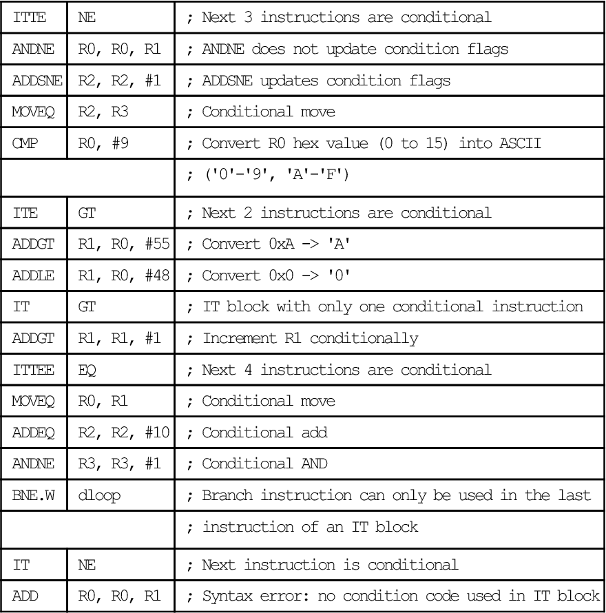
Example
| ITTE | NE | ; Next 3 instructions are conditional |
| ANDNE | R0, R0, R1 | ; ANDNE does not update condition flags |
| ADDSNE | R2, R2, #1 | ; ADDSNE updates condition flags |
| MOVEQ | R2, R3 | ; Conditional move |
| CMP | R0, #9 | ; Convert R0 hex value (0 to 15) into ASCII |
| ; ('0'-'9', 'A'-'F') | ||
| ITE | GT | ; Next 2 instructions are conditional |
| ADDGT | R1, R0, #55 | ; Convert 0xA -> 'A' |
| ADDLE | R1, R0, #48 | ; Convert 0x0 -> '0' |
| IT | GT | ; IT block with only one conditional instruction |
| ADDGT | R1, R1, #1 | ; Increment R1 conditionally |
| ITTEE | EQ | ; Next 4 instructions are conditional |
| MOVEQ | R0, R1 | ; Conditional move |
| ADDEQ | R2, R2, #10 | ; Conditional add |
| ANDNE | R3, R3, #1 | ; Conditional AND |
| BNE.W | dloop | ; Branch instruction can only be used in the last |
| ; instruction of an IT block | ||
| IT | NE | ; Next instruction is conditional |
| ADD | R0, R0, R1 | ; Syntax error: no condition code used in IT block |
A.8.4 TBB and TBH
Table Branch Byte and Table Branch Halfword.
Syntax
TBB [Rn, Rm]TBH [Rn, Rm, LSL #1]where
Rn is the register containing the address of the table of branch lengths. If Rn is PC, then the address of the table is the address of the byte immediately following the TBB or TBH instruction.
Rm is the index register. This contains an index into the table. For halfword tables, LSL #1 doubles the value in Rm to form the right offset into the table.
Operation
These instructions cause a PC-relative forward branch using a table of single byte offsets for TBB or halfword offsets for TBH. Rn provides a pointer to the table, and Rm supplies an index into the table. For TBB, the branch offset is twice the unsigned value of the byte returned from the table, and for TBH, the branch offset is twice the unsigned value of the halfword returned from the table. The branch occurs to the address at that offset from the address of the byte immediately after the TBB or TBH instruction.
Restrictions
Condition Flags
These instructions do not change the flags.
Examples
ADR.W R0, BranchTable_ByteTBB [R0, R1] ; R1 is the index, R0 is the base address of the ; branch tableCase1 ; an instruction sequence followsCase2 ; an instruction sequence followsCase3 ; an instruction sequence followsBranchTable_ByteDCB 0 ; Case1 offset calculationDCB ((Case2-Case1)/2) ; Case2 offset calculationDCB ((Case3-Case1)/2) ; Case3 offset calculation TBH [PC, R1, LSL #1] ; R1 is the index, PC is used as base of the ; branch tableBranchTable_HDCI ((CaseA - BranchTable_H)/2) ; CaseA offset calculationDCI ((CaseB - BranchTable_H)/2) ; CaseB offset calculationDCI ((CaseC - BranchTable_H)/2) ; CaseC offset calculationCaseA ; an instruction sequence followsCaseB ; an instruction sequence followsCaseC ; an instruction sequence followsA.9 Miscellaneous Instructions
Table A.11 shows the remaining Cortex-M3 instructions.
Table A.11
| Mnemonic | Brief Description | See |
| BKPT | Breakpoint | BKPT on page 397 |
| CPSID | Change Processor State, Disable Interrupts | CPS on page 398 |
| CPSIE | Change Processor State, Enable Interrupts | CPS on page 398 |
| DMB | Data Memory Barrier | DMB on page 398 |
| DSB | Data Synchronization Barrier | DSB on page 399 |
| ISB | Instruction Synchronization Barrier | ISB on page 399 |
| MRS | Move from special register to register | MRS on page 400 |
| MSR | Move from register to special register | MSR on page 400 |
| NOP | No Operation | NOP on page 401 |
| SEV | Send Event | SEV on page 402 |
| SVC | Supervisor Call | SVC on page 402 |
| WFE | Wait For Event | WFE on page 403 |
| WFI | Wait For Interrupt | WFI on page 403 |
A.9.1 BKPT
Breakpoint.
Syntax
BKPT #immwhere
Operation
The BKPT instruction causes the processor to enter Debug state. Debug tools can use this to investigate system state when the instruction at a particular address is reached.
imm is ignored by the processor. If required, a debugger can use it to store additional information about the breakpoint. ARM does not recommend the use of the BKPT instruction with an immediate value set to 0xAB for any purpose other than Semi-hosting.
The BKPT instruction can be placed inside an IT block, but it executes unconditionally, unaffected by the condition specified by the IT instruction.
Condition Flags
This instruction does not change the flags.
Examples
BKPT #0x3 ; Breakpoint with immediate value set to 0x3 (debugger can ; extract the immediate value by locating it using the PC)Note
ARM does not recommend the use of the BKPT instruction with an immediate value set to 0xAB for any purpose other than Semi-hosting.
A.9.2 CPS
Change Processor State.
Syntax
CPSeffect iflagswhere
Operation
CPS changes the PRIMASK and FAULTMASK special register values.
Restrictions
Condition Flags
This instruction does not change the condition flags.
Examples
CPSID i ; Disable interrupts and configurable fault handlers (set PRIMASK)CPSID f ; Disable interrupts and all fault handlers (set FAULTMASK)CPSIE i ; Enable interrupts and configurable fault handlers (clear PRIMASK)CPSIE f ; Enable interrupts and fault handlers (clear FAULTMASK)A.9.3 DMB
Data Memory Barrier.
Syntax
DMB{cond}where
Operation
DMB acts as a Data Memory Barrier. It ensures that all explicit memory accesses that appear, in program order, before the DMB instruction are completed before any explicit memory accesses that appear, in program order, after the DMB instruction. DMB does not affect the ordering or execution of instructions that do not access memory.
Condition Flags
This instruction does not change the flags.
Examples
DMB ; Data Memory BarrierA.9.4 DSB
Data Synchronization Barrier.
Syntax
DSB{cond}where
Operation
DSB acts as a special data synchronization memory barrier. Instructions that come after the DSB, in program order, do not execute until the DSB instruction completes. The DSB instruction completes when all explicit memory accesses before it complete.
Condition Flags
This instruction does not change the flags.
Examples
DSB ; Data Synchronization BarrierA.9.5 ISB
Instruction Synchronization Barrier.
Syntax
ISB{cond}where
Operation
ISB acts as an Instruction Synchronization Barrier. It flushes the pipeline of the processor so that all instructions following the ISB are fetched from cache or memory again, after the ISB instruction has been completed.
Condition Flags
This instruction does not change the flags.
Examples
ISB ; Instruction Synchronization BarrierA.9.6 MRS
Move the contents of a special register to a general-purpose register.
Syntax
MRS{cond} Rd, spec_regwhere
Operation
Use MRS in combination with MSR as part of a read-modify-write sequence for updating a PSR, for example, to clear the Q flag.
In process swap code, the programmer model state of the process being swapped out must be saved, including relevant PSR contents. Similarly, the state of the process being swapped in must also be restored. These operations use MRS in the state-saving instruction sequence and MSR in the state-restoring instruction sequence.
Note
BASEPRI_MAX is an alias of BASEPRI when used with the MRS instruction; see MSR on page 400.
Restrictions
Rd must not be SP and must not be PC.
Condition Flags
This instruction does not change the flags.
Examples
MRS R0, PRIMASK ; Read PRIMASK value and write it to R0A.9.7 MSR
Move the contents of a general-purpose register into the specified special register.
Syntax
MSR{cond} spec_reg, Rnwhere
Operation
The register access operation in MSR depends on the privilege level. Unprivileged software can only access the APSR. Privileged software can access all special registers.
In unprivileged software, writes to unallocated or execution state bits in the PSR are ignored.
Note
When you write to BASEPRI_MAX, the instruction writes to BASEPRI only if either
See “MRS” section on page 400.
Restrictions
Rn must not be SP and must not be PC.
Condition Flags
This instruction updates the flags explicitly based on the value in Rn.
Examples
MSR CONTROL, R1 ; Read R1 value and write it to the CONTROL registerA.9.8 NOP
No Operation.
Syntax
NOP{cond}where
Operation
NOP does nothing. NOP is not necessarily a time-consuming NOP. The processor might remove it from the pipeline before it reaches the execution stage.
Use NOP for padding, for example, to place the subsequence instruction on a 64-bit boundary.
Condition Flags
This instruction does not change the flags.
Examples
NOP ; No operationA.9.9 SEV
Send Event.
Syntax
SEV{cond}where
Operation
SEV is a hint instruction that causes an event to be signaled to all processors within a multiprocessor system. It also sets the local event register to 1. More details can be found in Section 14.3, Multiprocessor communication.
Condition Flags
This instruction does not change the flags.
Examples
SEV ; Send EventA.9.10 SVC
Supervisor Call.
Syntax
SVC{cond} #immwhere
Operation
The SVC instruction causes the SVC exception.
imm is ignored by the processor. If required, it can be retrieved by the exception handler to determine what service is being requested.
Condition Flags
This instruction does not change the flags.
Examples
SVC #0x32 ; Supervisor Call (SVC handler can extract the immediate value ; by locating it via the stacked PC)A.9.11 WFE
Wait For Event.
Syntax
WFE{cond}where
Operation
WFE is a hint instruction.
If the event register is 0, WFE suspends execution until one of the following events occurs:
• An exception, unless masked by the exception mask registers or the current priority level.
• An exception enters the pending state, if SEVONPEND in the System Control register is set.
• A Debug Entry request, if Debug is enabled.
• An event signaled by a peripheral or another processor in a multiprocessor system using the SEV instruction.
If the event register is 1, WFE clears it to 0 and returns immediately. Please refer to Section 14.2.1, Sleep Mode, for details of WFE and the event register.
Condition Flags
This instruction does not change the flags.
Examples
WFE ; Wait for eventA.9.12 WFI
Wait for Interrupt.
Syntax
WFI{cond}where
Operation
WFI is a hint instruction that suspends execution until one of the following events occurs:
Condition Flags
This instruction does not change the flags.