
Getting Started with the Keil RealView Microcontroller Development Kit
Publisher Summary
This chapter discusses the Keil RealView Microcontroller Development Kit (RealView MDK-ARM), a popular commercial development platform for the Cortex™-M3. A number of examples are provided with the RealView MDK-ARM, including some examples for various Cortex-M3 microcontroller products and evaluation boards available in the market. While creating the initial code, since the C library does not know about the actual hardware that is used, additional code is needed. After the software drivers that come with the evaluation board are set up, the program can be downloaded and tested. The debugger in μVision supports a number of in-circuit debuggers—an example is provided to show the using of the debugger in μVision to connect to the Luminary Evaluation Board to debug the application. The μVision Integrated Development Environment (IDE) comes with an instruction set simulator that can be used for debugging applications. Also, modifying the vector table—defined inside the file Startups—which is a standard startup code the tool prepares automatically is explained. A stopwatch example with interrupts with the Cortex Microcontroller Software Interface Standard (CMSIS) is provided and porting existing applications to use CMSIS is explained.
20.1 Overview
Various commercial development platforms are available for the Cortex™-M3. One of the popular choices is the Keil RealView Microcontroller Development Kit (RealView MDK-ARM). The RealView MDK-ARM contains various components as follows:
• μVision Integrated Development Environment (IDE)
• RealView Compilation Tools from ARM
• Detailed start-up code for microcontrollers
For learning about the Cortex-M3 with RealView MDK-ARM, it is not necessary to have Cortex-M3 hardware. The μVision environment contains an instruction set simulator that allows testing of simple programs that do not require a development board.
A free evaluation compact disc read-only memory (CD-ROM) for the Keil tool can be requested from the Keil web site (www.keil.com). This version is also included in a number of Cortex-M3 evaluation kits from various microcontroller vendors.
20.2 Getting Started with μVision
A number of examples are provided with the RealView MDK-ARM, including some examples for various Cortex-M3 microcontroller products and evaluation boards available on the market. In addition, you can also download device driver libraries from microcontroller vendor web sites, which also contain a number of examples. These examples provide a powerful set of device driver libraries that are ready to use. It's easy to modify the provided examples to start developing your application or you can develop your project from scratch. The following examples illustrate how this is done. The examples shown in this chapter are based on the version 3.80 of Keil MDK-ARM and on Luminary Micro LM3S811 devices.
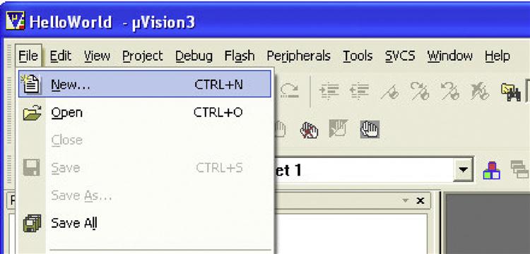
After installing the RealView MDK, you can start the μVision from the program menu. After installation, the μVision might start with a default project for a traditional ARM processor. We can close the current project and start a new one by selecting New Project in the pull-down menu (see Figure 20.1).
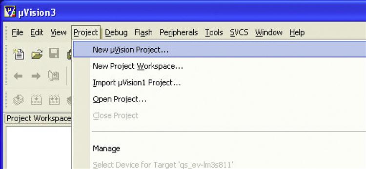
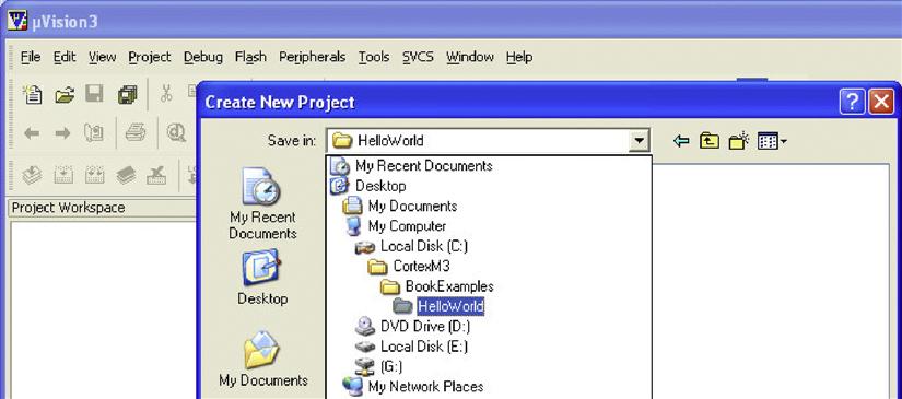
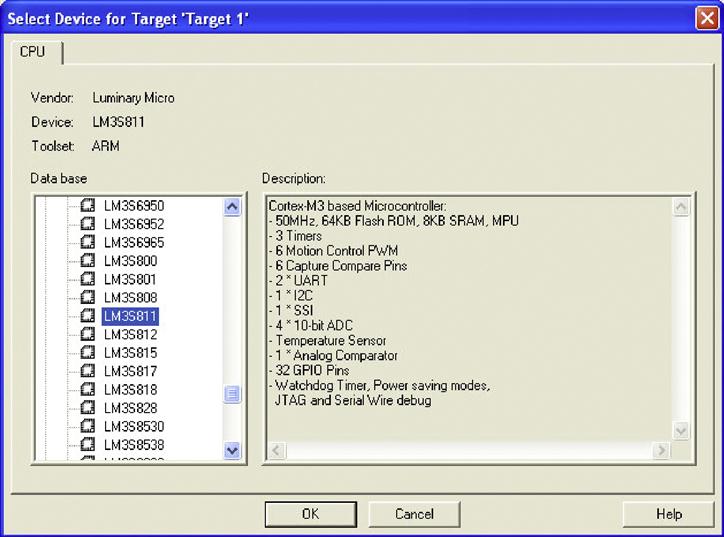
Figure 20.2 shows a new project directory called HelloWorld is created. Now, we need to select the targeted device for this project. In this example, the LM3S811 is selected (see Figure 20.3).
The software will then ask if you would like to use the default startup code. In this case, we select Yes (see Figure 20.4).

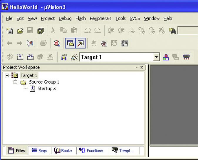
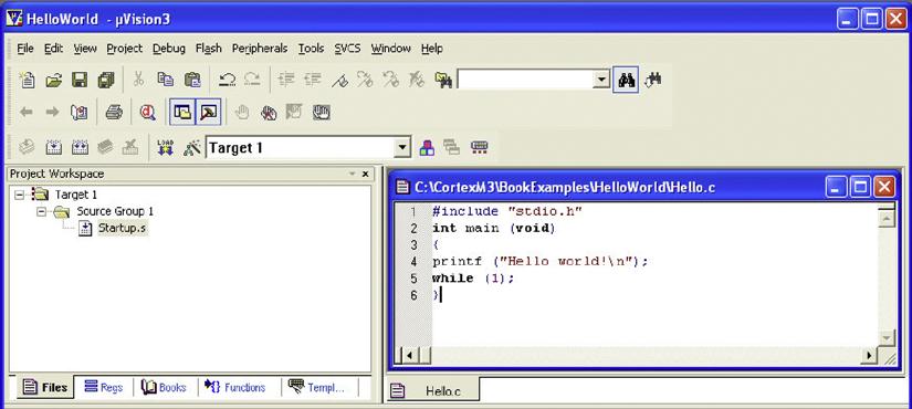
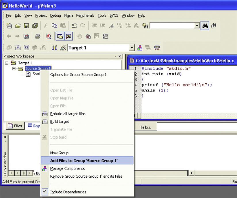
As Figure 20.5 shows, we now have a project called Hello with only one file, called Startup.s. We can create a new C program file containing the main program (see Figure 20.6). A text file is created and saved as hello.c (see Figure 20.7). As Figure 20.8 shows, we now need to add this file to our project by right-clicking Source Group 1.
Select the hello.c that we created and then close the Add File window. Now, the project contains two files (see Figure 20.9).

We can define the project setting by right clicking on the “Target 1” in the Project Workspace and selecting option for target “Target 1.” In the Target tab, we find that the memory layout details are already set up by the tool automatically (see Figure 20.10). From this dialog, you can also access various other project options by the tabs on the top.

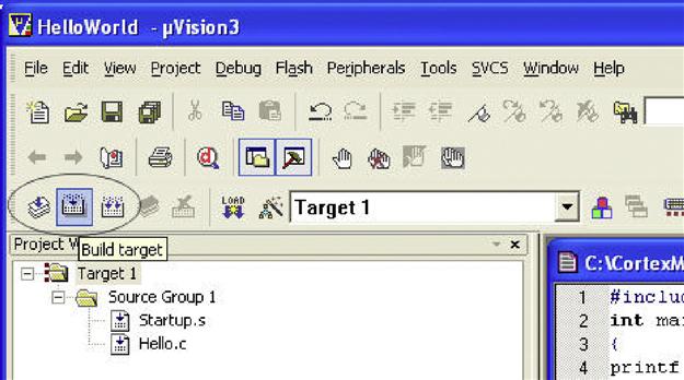
We can now compile the program. This can be done by clicking on the build target icons on the tool bar (see Figure 20.11) or by right-clicking Target 1 and selecting Build target.
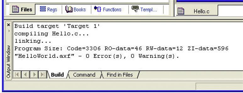
You should see the compilation success message in the output window (see Figure 20.12).
20.3 Outputting the “Hello World” Message Via Universal Asynchronous Receiver/Transmitter
In the program code we created, we used the printf function in the standard C library. Since the C library does not know about the actual hardware we are using, if we want to output the text message using real hardware, such as the universal asynchronous receiver/transmitter (UART) on a chip, we need additional code.
As mentioned earlier in this book, the implementation of output to actual hardware is often referred to as retargeting. Besides creating text output, the retargeting code might also include functions for error handling and program termination. In this example, only the text output retargeting is covered.
For the following code, the “Hello world” message is output to UART 0 of the LM3S811 device. The target system used is the Luminary Micro LM3S811 evaluation board. The board has a 6 MHz crystal as a clock source and an internal Phase-Locked Loop (PLL) module that can step up the clock frequency to 50 MHz after a simple setup process. The baud rate setting is 115 200 and is output to HyperTerminal running on a Windows PC.
To retarget the printf message, we need to implement the fputc function. In the following code, we have created an fputc function that calls the sendchar function, which carries out the UART control.
The SetupClockFreq routine sets the system clock to 50 MHz. The setup sequence is device dependent. The subroutine can also be used to set the clock frequency to 6 MHz if the “CLOCK50MHZ” compile directive is not set.
The UART initialization is carried out inside the Uart0Init subroutine. The setup process includes setting up the baud rate generator to provide a baud rate of 115 200; configuring the UART to 8 bits, no parity, and 1 stop bit; and switching the General Purpose Input/Output (GPIO) port to alternate function because the UART pins are shared with the GPIO port A. Before accessing the UART and the GPIO, the clocks for these blocks must be turned on. This is done by writing to SYSCTRL_RCGC1 and SYSCTRL_RCGC2.
The retargeting code is carried out by fputc, a predefined function name for character outputs. This function calls the sendchar function to output the character to the UART. The sendchar function outputs an extra carriage return character as a new line is detected. This is needed to get the text output correct on HyperTerminal; otherwise, the new text in the next line will overwrite the previous line of text.
After the hello.c program is modified to include the retargeting code, the program is compiled again.
20.4 Testing the Software
If you've got the Luminary Micro LM3S811 evaluation board, you can try out the example by downloading the compile program into Flash and getting the “Hello world” message display output from the HyperTerminal. Assuming that you have set up the software drivers that come with the evaluation board, you can download and test the program by following these steps.
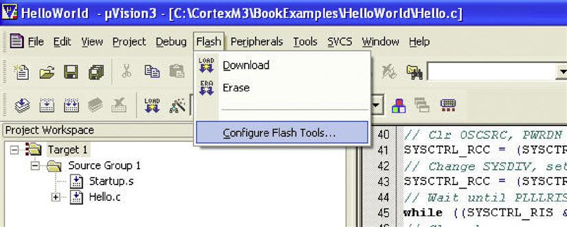
First, set up the Flash download option. This can be accessed from the Flash pull-down menu, as shown in Figure 20.13.
Inside this menu, we select the Luminary Evaluation Board as the download target for this example (see Figure 20.14). In this menu, we also can see that μVision supports a number of different debug hardware.

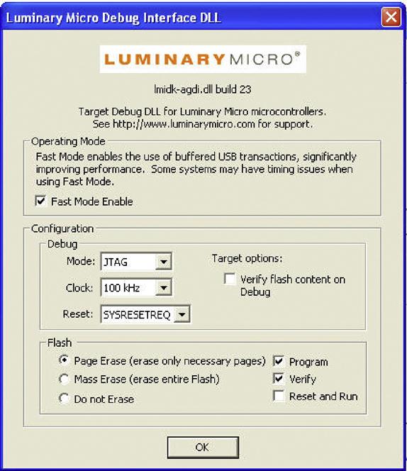
After selecting the flash download target, we might need to click on the Setting button to ensure that a suitable setting is used. (The settings are shown in Figure 20.15.)
Then, we can download the program to the Flash on a chip by selecting Download in the Flash pull-down menu. The message shown in Figure 20.16 will appear, indicating that the download is complete. Note: If you have the board already running with HyperTerminal, you might need to close HyperTerminal, disconnect the Universal Serial Bus (USB) cable from the PC, and reconnect before programming the Flash.

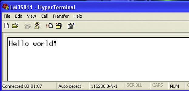
After the programming is completed, you can start HyperTerminal and connect to the board using the Virtual COM Port driver (via USB connection) and get the text display from the program running on the microcontroller (see Figure 20.17).
20.5 Using the Debugger
The debugger in μVision supports a number of in-circuit debuggers including the ULINK products (ULINK-2, ULINK-Pro, and ULINK-ME) from Keil (see Figure 20.18) and a number of debugger products from third parties.

Third party in-circuit debugger support includes the following:
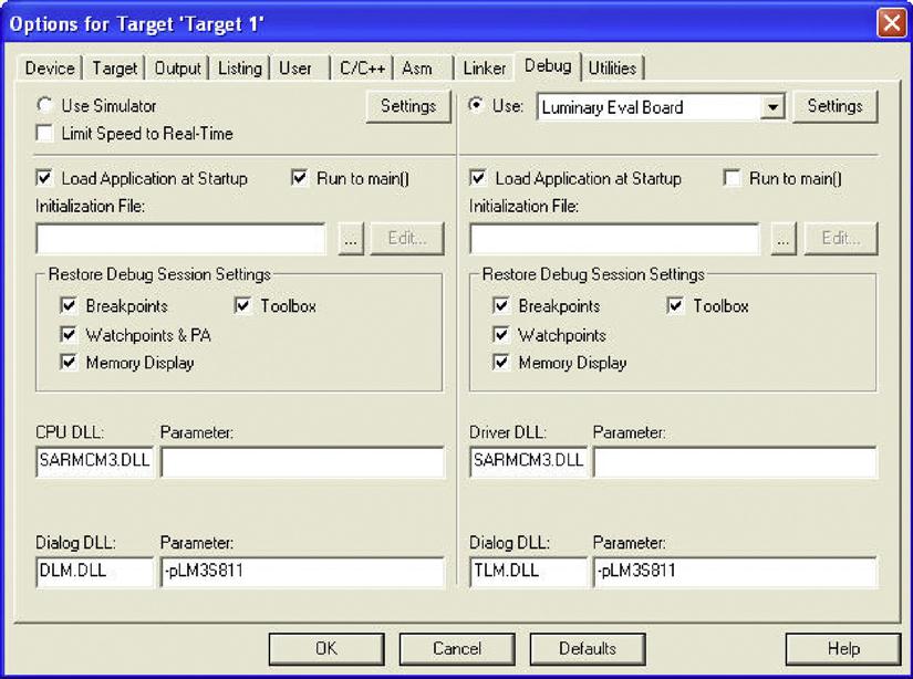
For this example, we will use the debugger in μVision to connect to the Luminary Evaluation Board to debug the application. By right-clicking the project Target 1 and selecting Options, we can access the debug option. In this case, we select to use the Luminary Eval Board for debugging (see Figure 20.19).
If you click on the “Settings” button next to the debug target selection, you can see the setting dialog as a Flash download option shown in Figure 20.15. You can select the debug protocol being used, debug clock speed and a few other settings. If you are using Keil ULINK-2/ULINK-Pro debugger for development, you can find more options (see Figure 20.20) via the setting button.
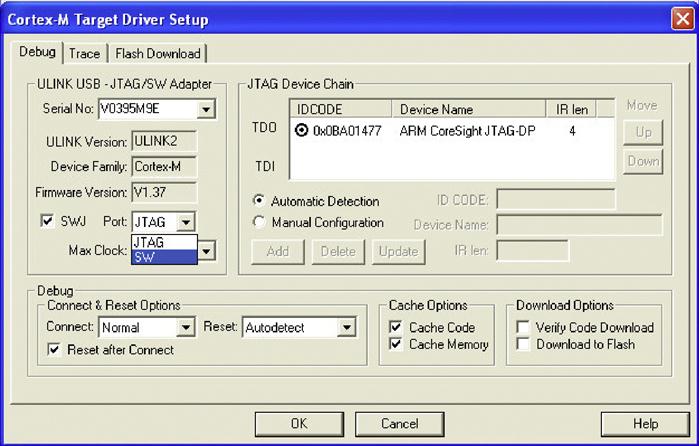
From here, you can select debug protocol (JTAG/Serial-Wire), debug communication clock speed, and trace and flash download options.
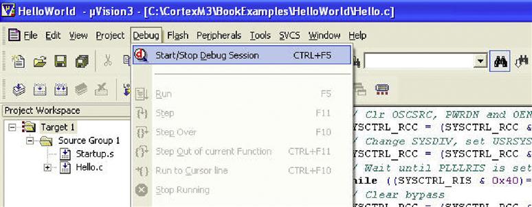
We can then start the debug session from the pull-down menu (see Figure 20.21). Note: If you are using virtual COM port with FTDI device driver and have the board already running with HyperTerminal, you might need to close HyperTerminal, disconnect the USB cable from the PC, and reconnect before starting the debug session.
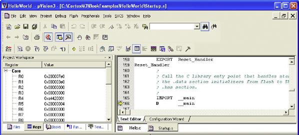
When the debugger starts, the IDE provides a register view to display register contents. You can also get the disassemble code window and see the current instruction address. In Figure 20.22, we can see that the core is halted at the Reset_Handler, the first instruction of the program execution.
For demonstration, a breakpoint is set to stop the program execution at the beginning of main. This can be done by right-clicking on the first line of code in the main program in the program code window and selecting Insert/Remove Breakpoint (see Figure 20.23). Note: We could also use the Run to main( ) feature in the debug option to get the program execution to stop at the beginning of main.
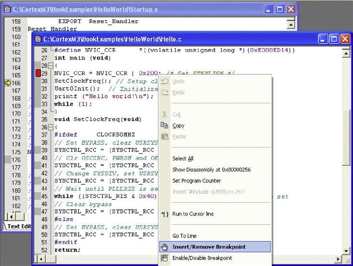
After the breakpoint is added, a red marker will be shown in the left side of the code line as shown in line 29 of the code in Figure 20.23. The program execution can then be started using the Run button on the tool bar (see Figure 20.24).
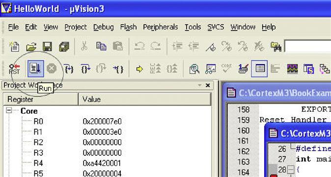
The program execution is then started, and it stops when it gets to the start of the main program (see Figure 20.25).

We can then use the stepping control of the tool bar to test our application and examine the results using the register window.
20.6 The Instruction Set Simulator
The μVision IDE also comes with an instruction set simulator that can be used for debugging applications. The operation is similar to using the debugger with hardware and is a useful tool for learning the Cortex-M3. To use the instruction set simulator, change the debug option of the project to Use Simulator (see Figure 20.26). Note that the simulator might not be able to simulate all hardware peripheral behaviors for some microcontroller products, so the UART interface code might not simulate correctly.

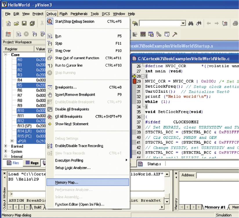
The simulator in μVision has full device level support for a wide range of Cortex-M3 devices. In some cases where full device simulation is not available, you might need to adjust the memory setting when using the simulator for debugging. This is done by accessing the Memory Map option after starting the debugging session (see Figure 20.27).
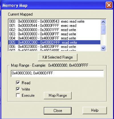
For example, you might need to add the UART memory address range to the memory map (see Figure 20.28). Otherwise, you will get an abort exception in the simulation when you try to access the UART. But in most cases, all of the required memory map should have been set up for you when you specified a microcontroller, so usually this is not necessary.
20.7 Modifying the Vector Table
In the previous example, the vector table is defined inside the file Startup.s, which is a standard startup code the tool prepares automatically. This file contains the vector table, a default reset handler, a default nonmaskable interrupt (NMI) handler, a default hard fault handler, and a default interrupt handler. These exception handlers might need to be customized or modified, depending on your application. For example, if a peripheral interrupt is required for your application, you need to change the vector table so that the Interrupt Service Routine (ISR) you created will be executed when the interrupt is triggered.
The default exception handlers are in the form of assembly code inside Startup.s. However, the exception handlers can be implemented in C or in a different assembly program file. In these cases, the IMPORT command in the assembler will be required to indicate that the interrupt handler address label is defined in another file.
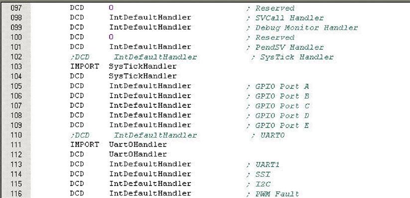
For example, if we want to add a SYSTICK exception handler and a UART exception handler, we can edit the file startup.s as shown in Figure 20.29 as follows:
• Comment out existing default interrupt handler for the exception.
• Add the IMPORT commands for the two exception vectors that are defined in the C-code. This is required if the handlers are in a separated C or assembly program file.
• Add the exception vectors in the vector table with Define Constant Data (DCD) command.
These modifications of startup code (startup.s) for adding exception handlers are not required with Cortex Microcontroller Software Interface Standard (CMSIS) compliant device driver libraries if the name of the exception handlers match the handler names specific in the CMSIS startup code. The next example illustrates how this is done.
20.8 Stopwatch Example with Interrupts with CMSIS
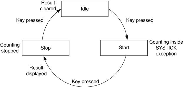
This example includes the use of exceptions, such as SYSTICK and the interrupt (UART0). The stopwatch to be developed has three states, as illustrated in Figure 20.30.
Based on the previous example, the stopwatch is controlled by the PC using the UART interface. To simplify the example code, we fix the operating speed at 50 MHz.
The timing measurement is carried out by the SYSTICK, which interrupts the processor at 100 Hz. The SYSTICK is running from the core clock frequency at 50 MHz. Every time the SYSTICK exception handler is executed and if the stopwatch is running, the counter variable TickCounter increments.
Since display of text via UART is relatively slow, the control of the stopwatch is handled inside the exception handler and the display of the text and stopwatch values is carried out in the main (thread level). A simple software state machine is used to control the start, stop, and clear of the stopwatch. The state machine is controlled via the UART handler, which is triggered every time a character is received.
Using the same procedure we used for the “Hello world” example, let's start a new project called stopwatch. Instead of having hello.c, a C program file called stopwatch.c is added. In addition, we added a number of other files from the CMSIS in the project.
In Figure 20.31, we can see that the Startup.s is replaced by startup_rvmdk.s, and lm3s_cmsis.h is included in the stopwatch.c. In addition, system_lm3s.c and core_cm3.c are also included in the project. The file system_lm3s.c contains SystemInit() function that we use in the program. The file core_cm3.c contains intrinsic functions. Despite that this example does not use any intrinsic function, this file is included for completeness.
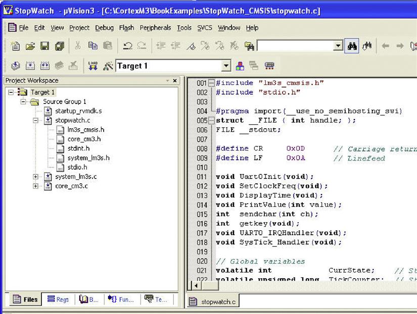
Some of these filenames are microcontroller vendor specific (e.g., startup_rvmdk.s, and lm3s_cmsis.h). These CMSIS files used in this project can be found in CMSIS compliant device driver libraries or from the CMSIS files available from www.onarm.com.
Use of CMSIS reduces the complexity of the stopwatch.c because peripheral register definitions and a number of system functions are provided by CMSIS.
When compared with the previous “Hello world” example, the UART initialization has changed slightly to enable interrupts when a character is received via the UART interface. To enable the UART interrupt request, the interrupt has to be enabled at the UART Interrupt Mask register, as well as at the NVIC. For the SYSTICK, only the exception control at the SYSTICK Control and Status register needs to be programmed.
In addition, a number of extra functions are added, including the UART and SYSTICK handlers, display functions, and SYSTICK initialization. Depending on the design of the peripheral, an exception/interrupt handler might need to clear the exception/interrupt request. In this case, the UART handler clears the UART interrupt request using the Interrupt Clear register (UART0->ICR).
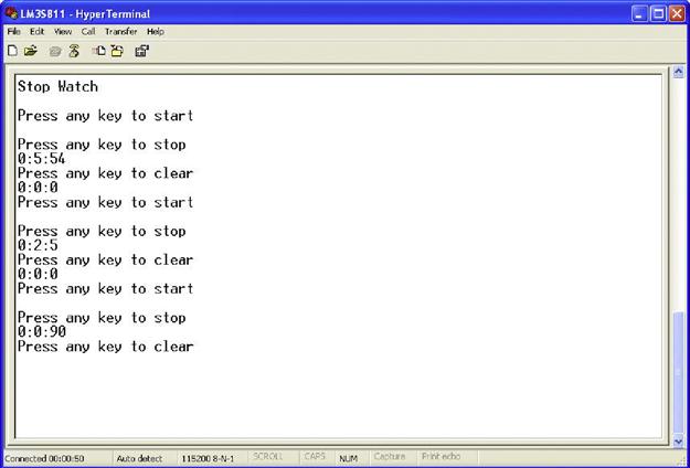
After the program is compiled and downloaded to the evaluation board, it can then be tested by connecting to a PC running HyperTerminal. Figure 20.32 shows the result.
20.9 Porting Existing Applications to Use CMSIS
It is easy to port existing Cortex-M3 applications to use CMSIS. The modifications include the following:
• Replace the default startup code with CMSIS startup code for the targeted microcontroller.
• Modify the project setup to include CMSIS file.
• Modify the program to include CMSIS header file
• Modify the register definitions with CMSIS register definitions
• Replace existing processor peripheral access functions with CMSIS processor access functions.
• Name of exception handlers might need to be modified to ensure that they match the exception handler names used by the CMSIS startup code.
• Peripheral setup code could be replaced by device driver library functions if available.
By changing the application code to use CMSIS, the application becomes more portable, as outlined in Chapter 10.