
Programming the Cortex-M3 Microcontrollers in NI LabVIEW
Publisher Summary
This chapter focuses on a different way to create applications for Cortex™-M3 microcontrollers besides C language and assembly language—LabVIEW—which can be used on PCs as well as ARM microcontrollers. It illustrates the various steps of developing a LabVIEW application with examples—from creating a simple application to defining the inputs and outputs for the applications—creating the application code, and building the application design. LabVIEW has several features—once the program is built, LabVIEW generates C code from the VI created. LabVIEW supports the creation of GUIs running on the debug host (PC), supports embedding C code inside a VI, during design simulation or test, the VI design environment can be used as a debugger by showing the values on data variables when it stops. Also, in addition to running LabVIEW using the evaluation kit, it can be ported to other Cortex-M3 microcontrollers or other ARM microcontrollers that are supported by the RTX Real-Time Kernel.
21.1 Overview
Besides C language and assembly language, there are other ways to create applications for Cortex™-M3 microcontrollers. One of the possible methods is by using the National Instruments LabVIEW graphical development environment. You can use LabVIEW on PCs as well as ARM microcontrollers, including Cortex-M3 microcontroller products.
21.2 What Is LabVIEW
There are several versions of the LabVIEW development environment, including versions for PC (available for Windows and Linux) and embedded platforms, which support a number of different embedded processors, including the Cortex-M3 processor and ARM7TDMI processor.
The LabVIEW graphical programming language supports all the features that you expect in any programming language such as looping, conditional execution, and the handling of different data types. The main difference in working with LabVIEW is that you design programs in diagrams. For example, a simple loop to compute the sum of 1–10 can be represented by the For Loop shown in Figure 21.1.
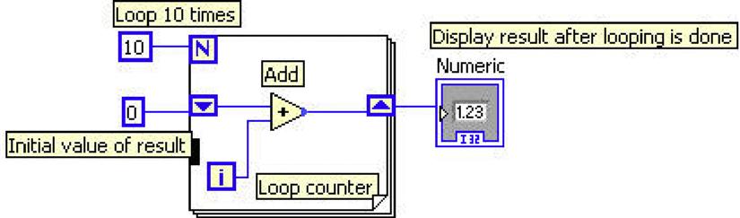
The flow of data is represented by connections; different data types are represented in different line styles; and different color and variables are represented by icons. For example, a U32 icon refers to an unsigned 32-bit integer and an I32 icon refers to a signed 32-bit integer.
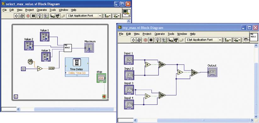
Similar to function calls and subroutines in traditional programming, in LabVIEW, you can design the software into hierarchy of modules called virtual instruments (VIs). Data passing into and outputs from sub-VIs indicate connection points so that a higher-hierarchy VI can connect input variables and output variables to it. For example, the right side of Figure 21.2 shows a sub-VI block diagram that takes four 32-bit integer inputs and selects the largest value as output. On the left side, the sub-VI is used to find the largest values from four 32-bit integer value sources: three from the slide bar control and one that is a random number.
The LabVIEW programming environment contains a large number of ready-to-use components that make your software development easier. These include common data-processing functions (e.g., abs—absolute value), signal processing functions, such as filter and spectral analysis, and many user interface components.
21.2.1 Typical Application Areas
So how does LabVIEW programming compare with traditional programming?
Ease of use—The LabVIEW programming environment makes it much easier to develop complex applications without the need to learn low-level hardware and software details. This allows different types of users, from students to scientists, to develop their applications without spending time learning processor architecture—they can focus on developing the algorithms and features. Domain-experts can now take advantage of the benefits of microcontroller designs.
Component library—The large number of software components available in LabVIEW also makes it easy to develop complex applications in a short time. The component library includes hundreds of mathematical and signal processing functions to quickly develop algorithms. Applications running on ARM microcontrollers can even connect to a graphical user interface (GUI) running on a PC so users can control the embedded system and observe the output easily.
Multithreading support—The graphical programming environment is concurrent in nature. It allows multiple threads to run at the same time. In contrast, in a traditional programming environment, it takes time for an inexperienced engineer to learn an embedded real time operating system (RTOS) well enough to develop a multithreading application.
Connectivity to test and data acquisition equipment—The LabVIEW programming environment provides easy-to-use interface components to data acquisition equipment communications systems as well as a large number of interface boards for industrial control and educational purposes.
The LabVIEW programming environment is popular in universities, laboratories, and scientific research institutions. It is commonly used in data acquisition, testing system automation, algorithm development and modeling, industrial control, and embedded system prototyping.
21.2.2 What You Need to Use LabVIEW and ARM
To start using LabVIEW for the Cortex-M3 microcontroller, you need the NI LabVIEW Embedded Module for ARM Microcontrollers, which includes the Keil ARM Microcontroller Development Kit (MDK-ARM). For evaluation, you can purchase a low-cost kit that includes an ARM microcontroller board (Cortex-M3/ARM7), Keil ULINK2 debugger, and the required development software, as shown in Figure 21.3 (a trial version of MDK-ARM is included on the CD). Details of the products are available on the National Instruments web site (www.ni.com/arm).

You can use LabVIEW with other Cortex-M3 microcontrollers or ARM7 microcontrollers. However, LabVIEW does not have device drivers for the peripherals of some of the microcontrollers. For these devices, you may need to develop the interface code in C and access it in LabVIEW.
21.3 Development Flow
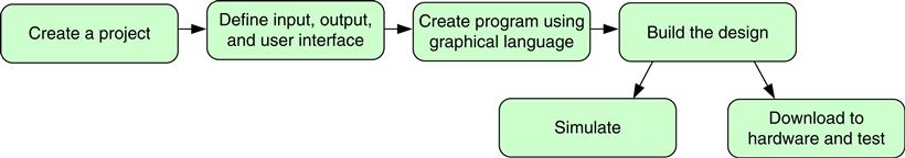
The development of a LabVIEW application typically involves the steps below and shown in Figure 21.4.
• Create a project and a VI: You can use the project wizard to create an ARM project easily. This includes setting up the targeted platform and device drivers. After the project creation, a VI (usually a blank one) is created.
• Define inputs and outputs: These can be hardware interfaces on the microcontroller or user interfaces running on the PC connected to the system. For hardware interfaces, you need to define the inputs and outputs as elemental input/output (I/O) in the project before you can use them in your VI design.
• Create the application using graphical programming.
• Simulate: It is possible to download the created execution image to the device simulation in the Keil MDK-ARM to test your application.
• Download to the microcontroller and test: By default, the program is downloaded to the microcontroller as a test when the compilation is done. You can use the LabVIEW interface to pause, stop, or single-step the execution. You can also probe the variable value by clicking the connection during execution.
• Front panel view: Containing a GUI of the VI.
• Block diagram view: Serving as a work-space for graphical programming.
When you create a VI, it has a blank front panel by default. You can then add control elements and indicator elements to define the inputs and outputs of the system. For instance, in the previous example of getting the largest integer from three inputs and a random value, the front panel may be similar to the one shown in Figure 21.5.

You can choose from a variety of control and indicator components in the VI libraries. After you add these controls and indicators, they become visible in the block diagram view. You can then customize properties like data types and create your graphical program by connecting them with various LabVIEW functions.
21.4 Example of a LabVIEW Project
21.4.1 Create the Project
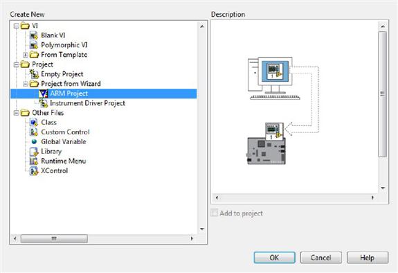
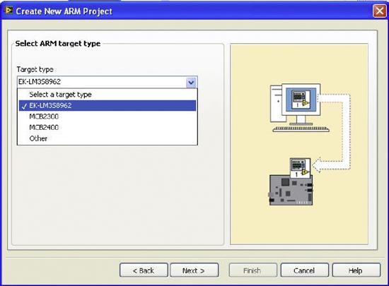
This example creates a simple application that samples analog signals and displays on the Organic LED (OLED) screen as a waveform. The first step is to use the project wizard to create a new project. From the LabVIEW startup screen, select “more” and then “ARM project,” as shown in Figure 21.6. Then you can create a blank VI, or use an existing one. For this example, create a new VI. Now you have the choice of target type. For this example, select the LM3S8962 evaluation kit (Figure 21.7).
In the final step, the project wizard builds the specification that allows you to run the project on a simulator. For this example, run it in hardware instead of selecting the simulator option. The project creation wizard also saves the project and a default blank VI.
21.4.2 Define Inputs and Outputs
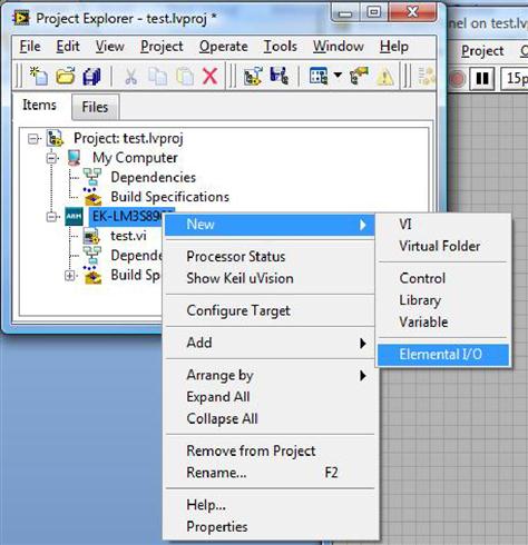
The next step of the project is to define the inputs and outputs for the applications. In this example, you need to define only the ADC0 input (the OLED display is controlled by library components, so you don't have to define it here). To complete that, right click on the target in the project window and select “New-> Elemental I/O” (Figure 21.8). Then define the input used in the project in the New Elemental I/O window, as shown in Figure 21.9.
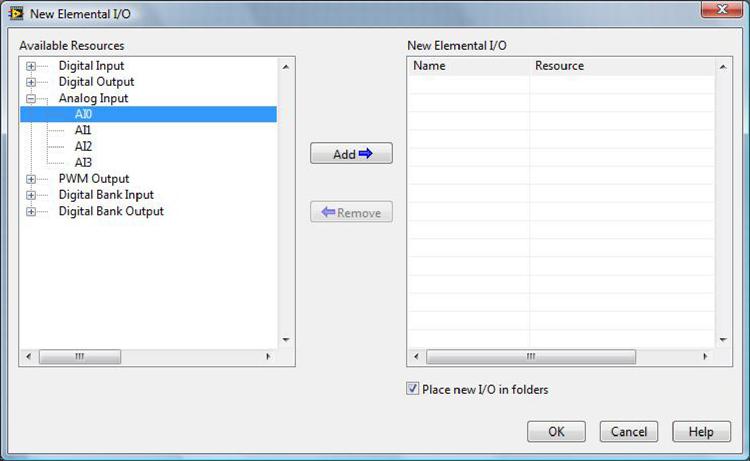
In this window, a number of other I/O options are available. For example, the push buttons, light emitting diode (LED), General Purpose Input/Output (GPIO), and Pulse Width Modulator (PWM) interfaces can help you simplify your project development.
21.4.3 Create the Program
Then you can create the application code in the block diagram view. LabVIEW features many functions and it is impossible to cover all of these in this chapter. LabVIEW has detailed documentation on how to create graphical programming elements, and each element has context-sensitive help information. In general, you can right click on the block diagram area to browse the available components (see Figure 21.10). For example, a number of the OLED screen controls are available in the ARM category.
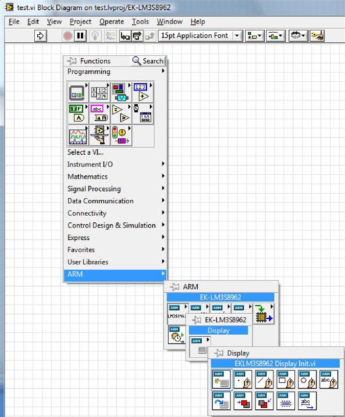
In addition to the OLED control, you can find the elemental I/O, Controller Area Network (CAN), Inter-Integrated Circuit (I2C), Serial Peripherial Interface (SPI), and interrupt control functions in the ARM category.
In the analog waveform display application, the program code is divided into two parts: on the left side of the block diagram, the code initializes the OLED screen, displays a startup screen, delays for a short period and then clears the screen and displays “Analog Input 0” at the top of the screen. Use this sub-VI, which is specific to the LM3S8962 evaluation board you are using, for the OLED controls provided in the LabVIEW Embedded Module for ARM Microcontrollers (Figure 21.11).
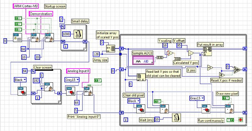
The right side of the block diagram features a While Loop that samples from ADC0 of the LM3S8962 and then displays the waveform by drawing a pixel on the screen. If the X-position is reached on the right side of the OLED screen, the X-position counter resets to 0.
The calculated Y position value is also stored into an array. The array has a size of 128 integers and is used to remove the old waveform before the new pixel is drawn on the screen.
21.4.4 Build the Design and Test the Application
Once you have completed the design, you can build the design and test the application. First click the arrow button on the tool bar. If the program contains an error, the arrow icon displays as broken to indicate that the program is not ready. You can click on it to report the errors detected in the program.
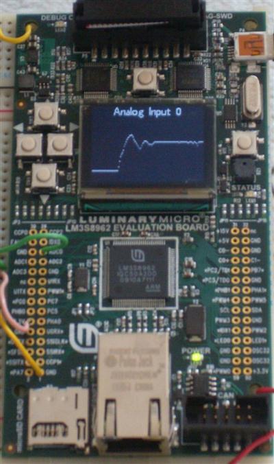
When you have completed the compile process, the program is downloaded to the board automatically and executed. In this example, the program has executed successfully and generated the waveform for an analog input (see Figure 21.12 on page 345).
21.5 How It Works
When you build the program, LabVIEW generates C code from the VI created. You can then compile C code using the MDK-ARM (Figure 21.13 on page 346). To run VI-s in parallel, the generated C code uses the RealView Real-Time Library (RL-ARM, www.keil.com/arm/rl-arm/), which works with the Keil RTX Real Time Kernel (www.keil.com/arm/rl-arm/kernel.asp).
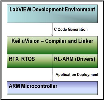
In addition to the capability of multithreading, using the RL-ARM provides access to a variety of drivers including timing control, Transmission Control Protocol/Internet Protocol (TCP/IP) stack, and CAN protocol stack.
21.6 Additional Features in LabVIEW
Semihosting: LabVIEW supports the creation of GUIs running on the debug host (PC). This is very useful for system prototyping because developing GUIs running on a microcontroller can be a time-consuming task. The LabVIEW library supports user-interface elements including switches, slide bars, and graphs, making it easy to create professional GUIs in just a few mouse clicks. During operation, the GUIs are running on the PC and the data are communicated to the running microcontroller target via the debug connection Joint Test Action Group, TCP/IP, or Serial. This allows you to control and access the results on the hardware in real time.
C code integration: LabVIEW supports embedding C code inside a VI. This is useful for creating new device drivers and handling data-processing tasks that you cannot complete using elements in LabVIEW.
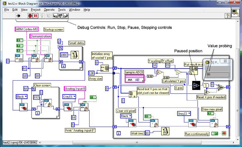
Debugging: Debugging is easy in the LabVIEW environment. During design simulation or test, you can use the VI design environment as a debugger by showing the values on data variables when it stops. The VI block diagram view provides pause, run, and single-stepping controls as well as value probing (Figure 21.14 on page 346).
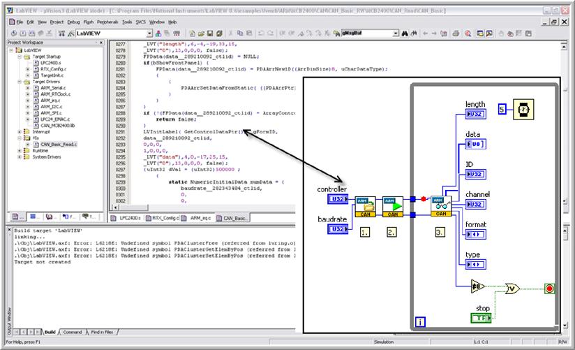
In addition, because the Keil μVision comes with a full-featured debugger, you can debug the application code you generated on LabVIEW using the μVision debugger (Figure 21.15 on page 347).
21.7 Porting to Another ARM Processor
In addition to running your LabVIEW application using the evaluation kit, you can port the application to other Cortex-M3 microcontrollers or other ARM microcontrollers that are supported by the RTX Real-Time Kernel. This typically involves the following steps:
• Port the RTX Real-Time Kernel: This step is not required for Cortex-M3 devices because the processor contains the required support for the RTX Real-Time Kernel. However, if you choose to use ARM7 microcontrollers, you may need this. A port for the RTX Real-Time Kernel may already be available in the Keil MDK-ARM installation options. You can determine if an RTX port is available for your ARM microcontroller by browsing the KeilARMStartup directory. If an RTX_Conf*.c is already available for the microcontroller target, then the RTX Real-Time Kernel has already been ported.
• Create the target in LabVIEW and incorporate the Keil toolchain: You can do this by manually creating the target folder.
• Integrate the Real-Time Agent Module for debugging: You may need to customize the RTX_config.c to include the Real-Time Agent Configuration option.
• Develop peripheral and I/O drivers: You can implement this step using the Element I/O Device Editor.
For more detailed information on the porting process, view the National Instruments online tutorial titled LabVIEW Embedded for ARM Porting Guide (http://zone.ni.com/devzone/cda/tut/p/id/6994).