
Cortex-M3 Troubleshooting Guide
E.1 Overview
One of the challenges of using the Cortex™-M3 is to locate problems when the program goes wrong. The Cortex-M3 processor provides a number of Fault Status registers to assist in troubleshooting (see Table E.1).
Table E.1
Fault Status Registers on Cortex-M3
| Address | Register | Full Name | Size |
| 0xE000ED28 | MMSR | MemManage Fault Status register | Byte |
| 0xE000ED29 | BFSR | Bus Fault Status register | Byte |
| 0xE000ED2A | UFSR | Usage Fault Status register | Half word |
| 0xE000ED2C | HFSR | Hard Fault Status register | Word |
| 0xE000ED30 | DFSR | Debug Fault Status register | Word |
| 0xE000ED3C | AFSR | Auxiliary Fault Status register | Word |

The MMSR, BFSR, and UFSR registers can be accessed in one go using a word transfer instruction. In this situation, the combined fault status register is called the Configurable Fault Status register (CFSR) (see Figure E.1).

For users of CMSIS compliant device drivers, these Fault Status registers can be accessed using the following symbols:
• SCB->CFSR: Configurable Fault Status register
• SCB->HFSR: Hard Fault Status register
Another important piece of information is the stacked program counter (PC). This is located in memory address [SP + 24] when a fault exception handler is entered. Because there are two stack pointers in the Cortex-M3, the fault handler might need to determine which stack pointer was used before obtaining the stacked PC.
In addition, for bus faults and memory management faults, you might also be able to determine the address that caused the fault. This is done by accessing the MemManage (Memory Management) Fault Address register (MMAR) and the Bus Fault Address register (BFAR). The contents of these two registers are only valid when the MMAVALID bit (in MMSR) or BFARVALID bit (in BFSR) is set. The MMAR and BFAR are physically the same register, so only one of them can be valid at a time (see Table E.2).
Table E.2
Fault Address Registers on Cortex-M3
| Address | Register | Full Name | Size |
| 0xE000ED34 | MMAR | MemManage Fault Address register | Word |
| 0xE000ED38 | BFAR | Bus Fault Address register | Word |

For users of CMSIS compliant device drivers, these Fault Address registers can be accessed using the following symbols:
Finally, the link register (LR) value when entering the fault handler might also provide hints about the cause of the fault. In the case of faults caused by invalid EXC_RETURN values, the value of LR when the fault handler is entered shows the previous LR value when the fault occurred. Fault handler can report the faulty LR value, and software programmers can then use this information to check why the LR ends up with an illegal return value.
E.2 Developing Fault Handlers
In most cases, fault handlers for development and for real running systems differ from one another. For software development, the fault handler should focus on reporting the type of error, whereas the fault handler for running systems will likely focus on system recovery actions. Here, we cover only the fault reporting because system recovery actions highly depend on design type and requirements.
In complex software, instead of outputting the results inside the fault handler, the contents of these registers can be copied to a memory block and then PendSV can be used to report the fault details later. This avoids potential faults in display or outputting routines causing lockup. For simple applications this might not matter, and the fault details can be output directly within the fault handler routine.
E.2.1 Report Fault Status Registers
The most basic step of a fault handler is to report the Fault Status register values. These include the following:
E.2.2 Report Stacked PC and Other Stacked Registers
In a fault handler, the step for getting the stacked PC is similar to the SVC example in this book.
This process can be carried out in assembly language as follows:
TST LR, #0x4 ; Test EXC_RETURN number in LR bit 2
ITTEE EQ ; if zero (equal) then
MRSEQ R0, MSP ; Main Stack was used, put MSP in R0
LDREQ R0,[R0,#24] ; Get stacked PC from stack.
MRSNE R0, PSP ; else, Process Stack was used, put PSP in R0
LDRNE R0,[R0,#24] ; Get stacked PC from stack.
Most Cortex-M3 developers use C for their projects. However, in C, it is difficult to locate and directly access the stack frame (stacked register values) as you cannot obtain the stack point value in C. To report the stack frame contents in your fault handler in C, you need to use a short assembly code to obtain stack point value, and then pass it to the fault reporting function in C as a parameter (see Figure E.2). The mechanism is identical to the SVC example in Chapter 12. The following example uses embedded assembler, which can work with RealView Development Suite (RVDS) and Keil RealView Microcontroller Development Kit (MDK-ARM).

The first part of the program is an assembly wrapper. The vector table should have the starting address of this wrapper code in the hard fault entry. This wrapper code copies the correct stack pointer value into R0, and passes it to the C function as a parameter.
// hard fault handler wrapper in assembly
// it extract the location of stack frame and pass it
// to handler in C as pointer.
__asm void hard_fault_handler_asm(void)
{TST LR, #4
ITE EQ
MRSEQ R0, MSP
MRSNE R0, PSP
B __cpp(hard_fault_handler_c )
}
The second part of the handler is in C. Here, we demonstrate how the stacked register contents and the Fault Status registers can be accessed.
// hard fault handler in C,
// with stack frame location as input parameter
void hard_fault_handler_c(unsigned int * hardfault_args)
{unsigned int stacked_r0;
unsigned int stacked_r1;
unsigned int stacked_r2;
unsigned int stacked_r3;
unsigned int stacked_r12;
unsigned int stacked_lr;
unsigned int stacked_pc;
unsigned int stacked_psr;
stacked_r0 = ((unsigned long) hardfault_args[0]);
stacked_r1 = ((unsigned long) hardfault_args[1]);
stacked_r2 = ((unsigned long) hardfault_args[2]);
stacked_r3 = ((unsigned long) hardfault_args[3]);
stacked_r12 = ((unsigned long) hardfault_args[4]);
stacked_lr = ((unsigned long) hardfault_args[5]);
stacked_pc = ((unsigned long) hardfault_args[6]);
stacked_psr = ((unsigned long) hardfault_args[7]);
printf ("[Hard fault handler]
");
printf ("R0 = %x
", stacked_r0);printf ("R1 = %x
", stacked_r1);printf ("R2 = %x
", stacked_r2);printf ("R3 = %x
", stacked_r3);printf ("R12 = %x
", stacked_r12);printf ("LR = %x
", stacked_lr);printf ("PC = %x
", stacked_pc);printf ("PSR = %x
", stacked_psr);printf ("BFAR = %x
", (*((volatile unsigned long *)(0xE000ED38))));printf ("CFSR = %x
", (*((volatile unsigned long *)(0xE000ED28))));printf ("HFSR = %x
", (*((volatile unsigned long *)(0xE000ED2C))));printf ("DFSR = %x
", (*((volatile unsigned long *)(0xE000ED30))));printf ("AFSR = %x
", (*((volatile unsigned long *)(0xE000ED3C))));exit(0); // terminate
return;
}
Please note that this handler will not work correctly if the stack pointer is pointing to an invalid memory region (e.g., because of stack overflow). This affects all C code as stack is required in C functions in most cases.
To help with debugging, we should also create a disassembled code list file so that we can locate the problem easily.
E.2.3 Read Fault Address Register
The Fault Address register can be erased after the MMARVALID or BFARVALID is cleared. To correctly access the Fault Address register, the following procedure should be used:
The reason for this procedure instead of reading valid bits first is to prevent a fault handler being preempted by another higher-priority fault handler after the valid bit is read, which could lead to the following erroneous fault-reporting sequence:
2. Valid bit is set, going to read BFAR/MMAR.
3. Higher-priority exception preempts existing fault handler, which generates another fault, causing another fault handler to be executed.
4. The higher-priority fault handler clears the BFARVALID/MMARVALID bit, causing the BFAR/MMAR to be erased.
5. After returning to the original fault handler, the BFAR/MMAR is read, but now the content is invalid and leads to incorrect reporting of the fault address.
Therefore, it is important to read the BFARVALID/MMARVALID after reading the Fault Address register to ensure that the address register content is valid.
E.2.4 Clear Fault Status Bits
After the fault reporting is done, the fault status bit in the FSR should be cleared so that next time the fault handler is executed, the previous faults will not confuse the fault handler. In addition, if the fault address valid bit is not clear, the Fault Address register will not get an update for the next fault.
E.2.5 Others
It is often necessary to save the contents of LR in the beginning of a fault handler. However, if the fault is caused by a stack error, pushing the LR to stack might just make things worst. As we know, R0–R3 and R12 should already been saved, so that we could copy LR to one of these registers before doing any function calls.
E.3 Understanding the Cause of the Fault
After obtaining the information we need, we can establish the cause of the problem. Tables E.3 through E.7 list some of the common reasons that faults occur.
Table E.3
MemManage Fault Status Register
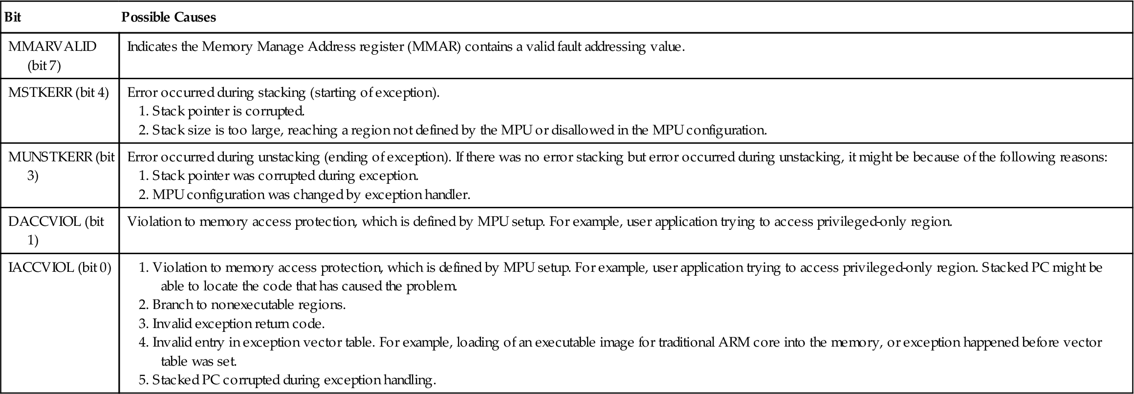
Table E.4

Table E.5
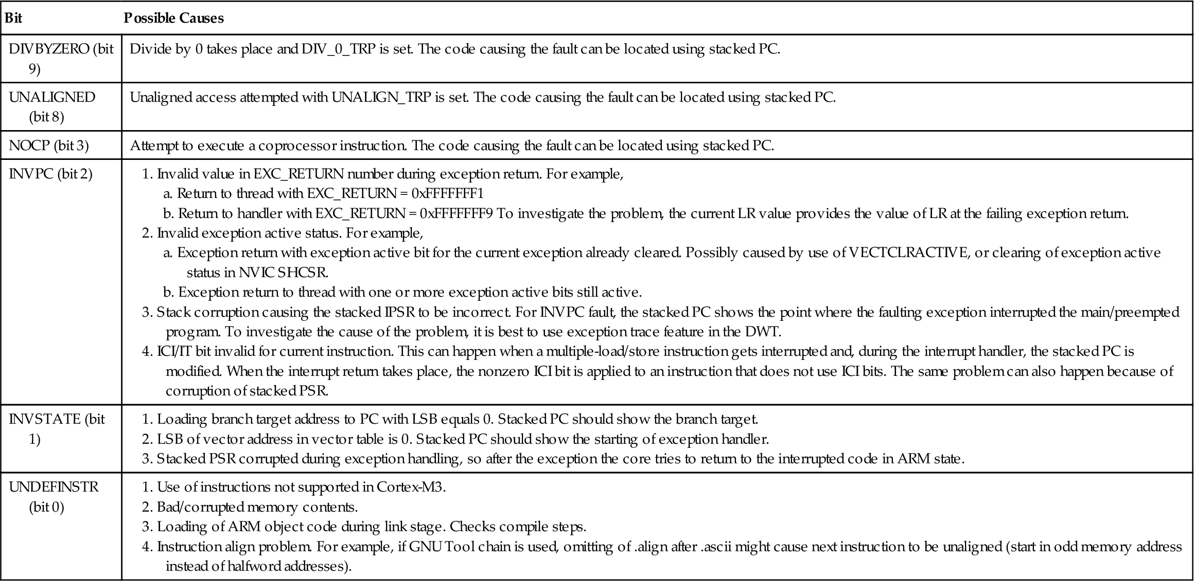
Table E.6
| Bit | Possible Causes |
| DEBUGEVF (bit 31) | Fault is caused by debug event: |
| FORCED (bit 30) | |
| VECTBL (bit 1) | Vector fetch failed. It could be caused by |
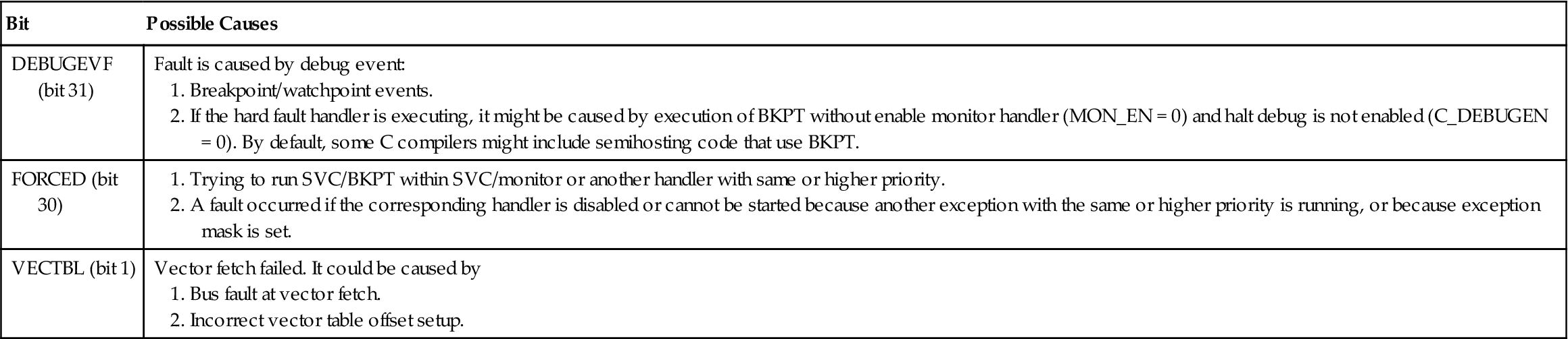
Table E.7

E.4 Other Possible Problems
A number of other common problems are in Table E.8.
Table E.8
