
The Carnot Cycle
The Carnot cycle, when acting as a heat engine, consists of the following four steps:
1. Reversible and isothermal expansion of the gas at the “hot” temperature, TH (isothermal heat addition). During this step (A to B in Figure A.1, 1 to 2 in Figure A.2), the expanding gas makes the piston do work on the surroundings. The gas expansion is propelled by the absorption of heat, designated Q1, from the high temperature reservoir.
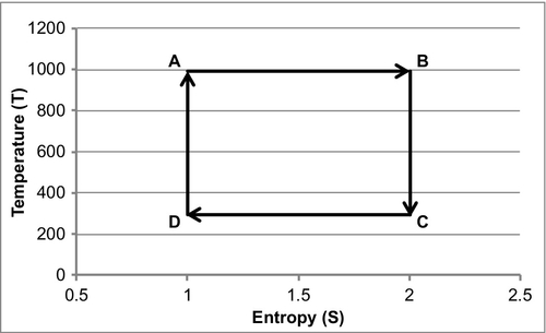
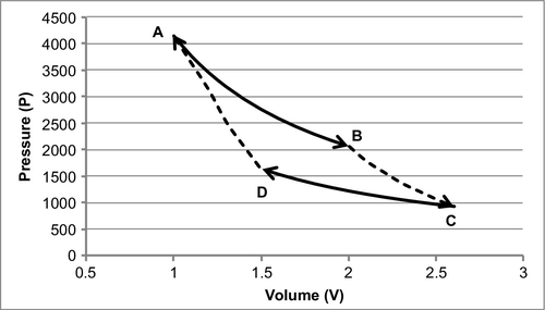
2. A reversible and adiabatic (isentropic) expansion of the gas (isentropic work output). Remember that adiabatic means that there is no heat transferred. Isentropic means that the entropy of the system remains constant. For this step (B to C in Figure A.1, 2 to 3 in Figure A.2), the piston and cylinder are assumed to be thermally insulated (adiabatic), and, as a result, they neither gain nor lose heat. The gas continues to expand, working on the surroundings. Expansion causes the gas to cool to the ‘cold’ temperature, TC.
3. Reversible isothermal compression of the gas at the “cold” temperature, TC (isothermal heat rejection). This is represented by C to D in Figure A.1 and 3 to 4 in Figure A.2. Now the surroundings do work on the gas, causing the quantity, or Q2, of heat to flow out of the gas to the low temperature reservoir.
4. Isentropic compression of the gas (isentropic work input). This is represented by D to A in Figure A.1 and 4 to 1 in Figure A.2. Once again, the piston and cylinder are assumed to be thermally insulated (or adiabatic). During this step, the surroundings do work on the gas, compressing it and causing the temperature to rise to TH. At this point, the gas is in the same state as at the start of step one.
The antithesis of a heat engine is a refrigerator. A heat engine burns fuel as part of a thermodynamic cycle to create heat that is converted into mechanical energy. A refrigerator sends the cycle in the opposite direction and uses electrical energy to create mechanical energy that then pumps heat from the cold body to the hotter body. The behavior of a Carnot engine or refrigerator is best understood by using a temperature-entropy (TS) diagram, in which the thermodynamic state is specified by a point on a graph with entropy (S) as the horizontal axis and temperature (T) as the vertical axis. For a simple system with a fixed amount of mass, any point on the graph will represent a particular state of the system. A thermodynamic process will consist of a curve connecting an initial state (A) and a final state (B). The area under the curve will be the heat.
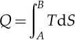
This is the amount of thermal energy transferred in the process. Equations A.1 and A.2 will use a little calculus to determine the area under the curves in Figures A.1 and A.2.
If the process moves to greater entropy, the area under the curve will be the amount of heat absorbed by the system in that process. If the process moves towards lesser entropy, it will be the amount of heat removed. For any cyclic process, there will be an upper portion of the cycle and a lower portion. For a clockwise cycle, the area under the upper portion will be the thermal energy absorbed during the cycle, while the area under the lower portion will be the thermal energy removed during the cycle. The area inside the cycle will then be the difference between the two. Given that the internal energy of the system must have returned to its initial value, this difference must be the amount of work done by or on the system over the cycle. Referring to Figure A.1 mathematically, for a reversible process we may write the amount of work done over a cyclic process as:

As dU is an exact differential, its integral over any closed loop is zero, and it follows that the area inside the loop on the T-S diagram is equal to the total work performed if the loop is traversed in a clockwise direction. If the loop is traversed in a counterclockwise direction, it will be equal to the total work done on the system.
An evaluation of the above integral is particularly simple for the Carnot cycle. The amount of energy transferred as work is:

The total amount of thermal energy transferred between the hot reservoir and the system will be:

The total amount of thermal energy transferred between the system and the cold reservoir will be:
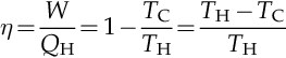
The efficiency, η, is defined as the work produced divided by the heat input from the hot reservoir:
Where,
W is the work done by the system (energy exiting the system as work).
QH is the heat put into the system (heat energy entering the system).
TC is the absolute temperature of the cold reservoir.
TH is the absolute temperature of the hot reservoir.
SB is the maximum system entropy.
SA is the minimum system entropy.