11.4. DISTILLATION WITH REFLUX AND McCABE–THIELE METHOD
11.4A. Introduction to Distillation with Reflux
Rectification (fractionation) or stage distillation with reflux, from a simplified point of view, can be considered to be a process in which a series of flash-vaporization stages are arranged in a series in such a manner that the vapor and liquid products from each stage flow counter current to each other. The liquid in a stage is conducted or flows to the stage below and the vapor from a stage flows upward to the stage above. Hence, in each stage a vapor stream V and a liquid stream L enter, are mixed and equilibrated, and a vapor and a liquid stream leave in equilibrium. This process flow diagram was shown in Fig. 10.3-1 for a single stage and an example given in Example 11.2-1 for a benzene–toluene mixture.
For the countercurrent contact with multiple stages in Fig. 10.3-2, the material-balance or operating-line equation (10.3-13) was derived, which relates the concentrations of the vapor and liquid streams passing each other in each stage. In a distillation column the stages (referred to as sieve plates or trays) in a distillation tower are arranged vertically, as shown schematically in Fig. 11.4-1.
Figure 11.4-1. Process flow of a fractionating tower containing sieve trays.
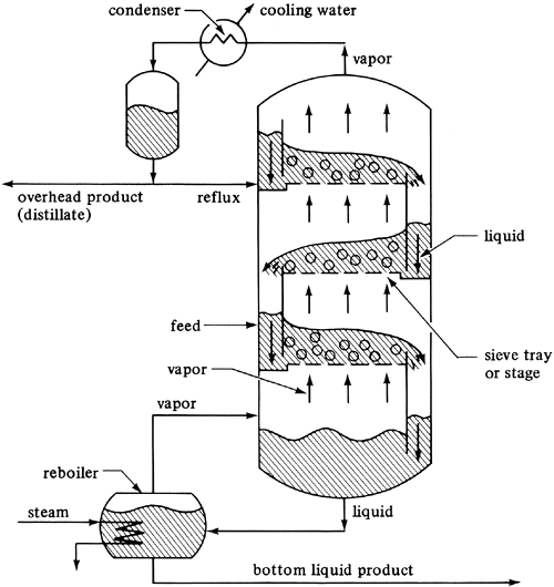
The feed enters the column in Fig. 11.4-1 somewhere in the middle of the column. If the feed is liquid, it flows down to a sieve tray or stage. Vapor enters the tray and bubbles through the liquid on this tray as the entering liquid flows across. The vapor and liquid leaving the tray are essentially in equilibrium. The vapor continues up to the next tray or stage, where it is again contacted with a downflowing liquid. In this case the concentration of the more volatile component (the lower-boiling component A) is being increased in the vapor from each stage going upward and decreased in the liquid from each stage going downward. The final vapor product coming overhead is condensed in a condenser and a portion of the liquid product (distillate) is removed, which contains a high concentration of A. The remaining liquid from the condenser is returned (refluxed) as a liquid to the top tray.
The liquid leaving the bottom tray enters a reboiler, where it is partially vaporized, and the remaining liquid, which is lean in A or rich in B, is withdrawn as liquid product. The vapor from the reboiler is sent back to the bottom stage or tray. Only three trays are shown in the tower of Fig. 11.4-1. In most cases the number of trays is much greater. In the sieve tray the vapor enters through an opening and bubbles up through the liquid to provide intimate contact between the liquid and vapor on the tray. In a theoretical tray the vapor and liquid leaving are in equilibrium. The reboiler can be considered as a theoretical stage or tray.
11.4B. McCabe–Thiele Method of Calculation for Number of Theoretical Stages
1. Introduction and assumptions
A mathematical–graphical method for determining the number of theoretical trays or stages needed for a given separation of a binary mixture of A and B has been developed by McCabe and Thiele. The method uses material balances around certain parts of the tower, which give operating lines somewhat similar to Eq. (10.3-13), and the x-y equilibrium curve for the system.
The main assumption made in the McCabe–Thiele method is that there must be equimolar overflow through the tower between the feed inlet and the top tray and the feed inlet and bottom tray. This is shown in Fig. 11.4-2, where liquid and vapor streams enter a tray, are equilibrated, and leave. A total material balance gives
Equation 11.4-1
![]()
Figure 11.4-2. Vapor and liquid flows entering and leaving a tray.

A component balance on A gives
Equation 11.4-2
![]()
where Vn+1 is mol/h of vapor from tray n + 1, Ln is mol/h liquid from tray n, yn+1 is mole fraction of A in Vn+1, and so on. The compositions yn and xn are in equilibrium and the temperature of the tray n is Tn. If Tn is taken as a datum, it can be shown by a heat balance that the sensible heat differences in the four streams are quite small if heats of solution are negligible. Hence, only the latent heats in streams Vn+1 and Vn are important. Since molar latent heats for chemically similar compounds are almost the same, Vn+1 = Vn and Ln = Ln−1. Therefore, we have constant molal overflow in the tower.
2. Equations for enriching section
In Fig. 11.4-3 a continuous-distillation column is shown, with feed being introduced to the column at an intermediate point and an overhead distillate product and a bottoms product being withdrawn. The upper part of the tower above the feed entrance is called the enriching section, since the entering feed of binary components A and B is enriched in this section, so that the distillate is richer in A than the feed. The tower is at steady state.
Figure 11.4-3. Distillation column showing material-balance sections for McCabe–Thiele method.

An overall material balance around the entire column in Fig. 11.4-3 states that the entering feed of F mol/h must equal the distillate D in mol/h plus the bottoms W in mol/h:
Equation 11.4-3
![]()
A total material balance on component A gives
Equation 11.4-4
![]()
In Fig. 11.4-4a the distillation-tower section above the feed, the enriching section, is shown schematically. The vapor from the top tray having a composition y1 passes to the condenser, where it is condensed so that the resulting liquid is at the boiling point. The reflux stream L mol/h and distillate D mol/h have the same composition, so y1 = xD. Since equimolal overflow is assumed, L1 = L2 = Ln and V1 = V2 = Vn = Vn+1.
Figure 11.4-4. Material balance and operating line for enriching section: (a) schematic of tower, (b) operating and equilibrium lines.
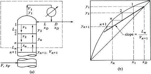
Making a total material balance over the dashed-line section in Fig. 11.4-4a,
Equation 11.4-5
![]()
Making a balance on component A,
Equation 11.4-6
![]()
Solving for yn+1, the enriching-section operating line is
Equation 11.4-7
![]()
Since Vn+1 = Ln + D, Ln/Vn+1 = R/(R + 1) and Eq. (11.4-7) becomes
Equation 11.4-8
![]()
where R = Ln/D = reflux ratio = constant. Equation (11.4-7) is a straight line on a plot of vapor composition versus liquid composition. It relates the compositions of two streams passing each other and is plotted in Fig. 11.4-4b. The slope is Ln/Vn+1 or R/(R + 1), as given in Eq. (11.4-8). It intersects the y = x line (45° diagonal line) at x = xD. The intercept of the operating line at x = 0 is y = xD/(R + 1).
The theoretical stages are determined by starting at xD and stepping off the first plate to x1. Then y2 is the composition of the vapor passing the liquid x1. In a similar manner, the other theoretical trays are stepped off down the tower in the enriching section to the feed tray.
3. Equations for stripping section
Making a total material balance over the dashed-line section in Fig. 11.4-5a for the stripping section of the tower below the feed entrance,
Equation 11.4-9
![]()
Figure 11.4-5. Material balance and operating line for stripping section: (a) schematic of tower, (b) operating and equilibrium lines.
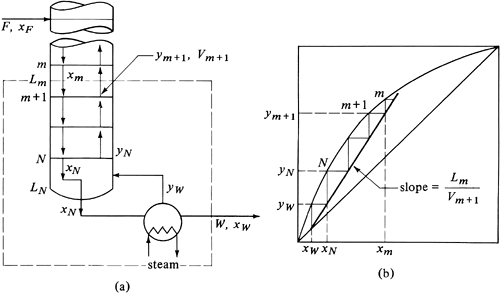
Making a balance on component A,
Equation 11.4-10
![]()
Solving for ym+1, the stripping-section operating line is
Equation 11.4-11
![]()
Again, since equimolal flow is assumed, Lm = LN = constant and Vm+1 = VN = constant. Equation (11.4-11) is a straight line when plotted as y versus x in Fig. 11.4-5b, with a slope of Lm/Vm+1. It intersects the y = x line at x = xW. The intercept at x = 0 is y = −WxW/Vm+1.
Again the theoretical stages for the stripping section are determined by starting at xW, going up to yW, and then across to the operating line, and so on.
4. Effect of feed conditions
The condition of the feed stream F entering the tower determines the relation between the vapor Vm in the stripping section and Vn in the enriching section as well as between Lm and Ln. If the feed is part liquid and part vapor, the vapor will add to Vm to give Vn.
For convenience, we represent the condition of the feed by the quantity q, which is defined as
Equation 11.4-12
![]()
If the feed enters at its boiling point, the numerator of Eq. (11.4-12) is the same as the denominator, and q = 1.0. Equation (11.4-12) can also be written in terms of enthalpies:
Equation 11.4-13
![]()
where HV is the enthalpy of the feed at the dew point, HL the enthalpy of the feed at the boiling point (bubble point), and HF the enthalpy of the feed at its entrance conditions. If the feed enters as vapor at the dew point, q = 0. For cold liquid feed q > 1.0, for superheated vapor q < 0, and for the feed being part liquid and part vapor, q is the fraction of feed that is liquid.
We can also look at q as the number of moles of saturated liquid produced on the feed plate by each mole of feed added to the tower. In Fig. 11.4-6 a diagram shows the relationship between flows above and below the feed extrance. From the definition of q, the following equations hold:
Equation 11.4-14
![]()
Equation 11.4-15
![]()
Figure 11.4-6. Relationship between flows above and below the feed entrance.

The point of intersection of the enriching and the stripping operating-line equations on an x-y plot can be derived as follows. Rewriting Eqs. (11.4-6) and (11.4-10) as follows without the tray subscripts:
Equation 11.4-16
![]()
Equation 11.4-17
![]()
where the y and x values are the point of intersection of the two operating lines. Subtracting Eq. (11.4-16) from (11.4-17),
Equation 11.4-18
![]()
Substituting Eqs. (11.4-4), (11.4-14), and (11.4-15) into Eq. (11.4-18) and rearranging,
Equation 11.4-19
![]()
This equation is the q-line equation and is the locus of the intersection of the two operating lines. Setting y = x in Eq. (11.4-19), the intersection of the q-line equation with the 45° line is y = x = xF, where xF is the overall composition of the feed.
In Fig. 11.4-7 the q line is plotted for various feed conditions given below the figure. The slope of the q line is q/(q − 1). For example, for the liquid below the boiling point, q > 1, and the slope is >1.0, as shown. The enriching and operating lines are plotted for the case of a feed of part liquid and part vapor, and the two lines intersect on the q line. A convenient way to locate the stripping operating line is to first plot the enriching operating line and the q line. Then draw the stripping line between the intersection of the q line and enriching operating line and the point y = x = xW.
Figure 11.4-7. Location of the q line for various feed conditions: liquid below boiling point (q > 1), liquid at boiling point (q = l), liquid + vapor (0 < q < 1), saturated vapor (q = 0).

5. Location of the feed tray in a tower and number of trays
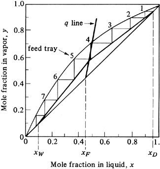
To determine the number of theoretical trays needed in a tower, the stripping and operating lines are drawn to intersect on the q line, as shown in Fig. 11.4-8. Starting at the top at xD, the trays are stepped off. For trays 2 and 3, the steps can go to the enriching operating line, as shown in Fig. 11.4-8a. At step 4 the step goes to the stripping line. A total of about 4.6 theoretical steps are needed. The feed enters on tray 4.
Figure 11.4-8. Method of stepping off number of theoretical trays and location of feed plate: (a) improper location of feed on tray 4, (b) proper location of feed on tray 2 to give minimum number of steps.

For the correct method, the shift is made on step 2 to the stripping line, as shown in Fig. 11.4-8b. A total of only about 3.7 steps are needed, with the feed on tray 2. To keep the number of trays to a minimum, the shift from the enriching to the stripping operating line should be made at the first opportunity after passing the operating-line intersection.
In Fig. 11.4-8b the feed is part liquid and part vapor, since 0 < q < 1. Hence, in adding the feed to tray 2, the vapor portion of the feed is separated and added beneath plate 2 and the liquid added to the liquid from above entering tray 2. If the feed is all liquid, it should be added to the liquid flowing to tray 2 from the tray above. If the feed is all vapor, it should be added below tray 2 and join the vapor rising from the plate below.
Since a reboiler is considered a theoretical step, when the vapor yW is in equilibrium with xW, as in Fig. 11.4-5b, the number of theoretical trays in a tower is equal to the number of theoretical steps minus one.
EXAMPLE 11.4-1. Rectification of a Benzene–Toluene MixtureA liquid mixture of benzene–toluene is to be distilled in a fractionating tower at 101.3 kPa pressure. The feed of 100 kg mol/h is liquid, containing 45 mol % benzene and 55 mol % toluene, and enters at 327.6 K (130°F). A distillate containing 95 mol % benzene and 5 mol % toluene and a bottoms containing 10 mol % benzene and 90 mol % toluene are to be obtained. The reflux ratio is 4:1. The average heat capacity of the feed is 159 kJ/kg mol · K (38 btu/lb mol · °F) and the average latent heat 32 099 kJ/kg mol (13 800 btu/lb mol). Equilibrium data for this system are given in Table 11.1-1 and Fig. 11.1-1. Calculate the kg moles per hour distillate, kg moles per hour bottoms, and the number of theoretical trays needed. Solution: The given data are F = 100 kg mol/h, xF = 0.45, xD = 0.95, xW = 0.10, and R = Ln/D = 4. For the overall material balance substituting into Eq. (11.4-3), Equation 11.4-3
Substituting into Eq. (11.4-4) and solving for D and W, Equation 11.4-4
For the enriching operating line, using Eq. (11.4-8),
The equilibrium data from Table 11.1-1 and the enriching operating line above are plotted in Fig. 11.4-9. Figure 11.4-9. McCabe–Thiele diagram for distillation of benzene–toluene for Example 11.4-1.
Next, the value of q is calculated. From the boiling-point diagram, Fig. 11.1-1, for xF = 0.45 the boiling point of the feed is 93.5°C or 366.7 K (200.3°F). From Eq. (11.4-13), Equation 11.4-13
The value of HV − HL = latent heat = 32 099 kJ/kg mol. The numerator of Eq. (11.4-13) is Equation 11.4-20
Also, Equation 11.4-21
where the heat capacity of the liquid feed cpL = 159 kJ/kg mol · K, TB = 366.7 K (boiling point of feed), and TF = 327.6 K (inlet feed temperature). Substituting Eqs. (11.4-20) and (11.4-21) into (11.4-13), Equation 11.4-22
Substituting the known values into Eq. (11.4-22),
From Eq. (11.4-19), the slope of the q line is
The q line is plotted in Fig. 11.4-9 starting at the point y = xF = 0.45 with a slope of 6.12. The stripping operating line is drawn connecting the point y = x = xW = 0.10 with the intersection of the q line and the enriching operating line. Starting at the point y = x = xD, the theoretical steps are drawn in, as shown in Fig. 11.4-9. The number of theoretical steps is 7.6, or 7.6 steps minus a reboiler, which gives 6.6 theoretical trays. The feed is introduced on tray 5 from the top. |
11.4C. Total and Minimum Reflux Ratio for McCabe–Thiele Method
1. Total reflux
In distillation of a binary mixture A and B, the feed conditions, distillate composition, and bottoms composition are usually specified and the number of theoretical trays are to be calculated. However, the number of theoretical trays needed depends upon the operating lines. To fix the operating lines, the reflux ratio R = Ln/D at the top of the column must be set.
One of the limiting values of reflux ratio is that of total reflux, or R = ∞. Since R = Ln/D and, by Eq. (11.4-5),
Equation 11.4-5
![]()
then Ln is very large, as is the vapor flow Vn. This means that the slope R/(R + 1) of the enriching operating line becomes 1.0 and the operating lines of both sections of the column coincide with the 45° diagonal line, as shown in Fig. 11.4-10.
Figure 11.4-10. Total reflux and minimum number of trays by McCabe–Thiele method.

The number of theoretical trays required is obtained as before by stepping off the trays from the distillate to the bottoms. This gives the minimum number of trays that can possibly be used to obtain the given separation. In actual practice, this condition can be realized by returning all the overhead condensed vapor V1 from the top of the tower back to the tower as reflux, that is, total reflux. Also, all the liquid in the bottoms is reboiled. Hence, all the products distillate and bottoms are reduced to zero flow, as is the fresh feed to the tower.
This condition of total reflux can also be interpreted as requiring infinite sizes of condenser, reboiler, and tower diameter for a given feed rate.
If the relative volatility α of the binary mixture is approximately constant, the following analytical expression by Fenske can be used to calculate the minimum number of theoretical steps Nm when a total condenser is used:
Equation 11.4-23

For small variations in α, αav = (α1αW)1/2, where α1 is the relative volatility of the overhead vapor and αW is the relative volatility of the bottoms liquid.
2. Minimum reflux ratio
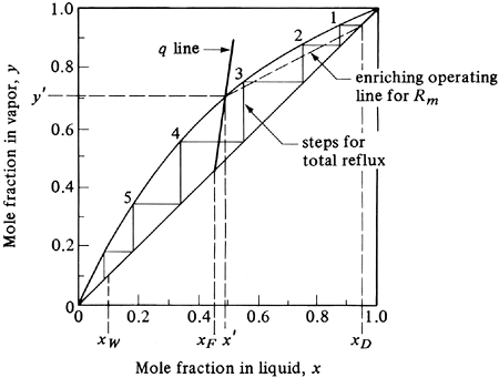
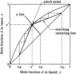
The minimum reflux ratio can be defined as the reflux ratio Rm that will require an infinite number of trays for the given desired separation of xD and xW. This corresponds to the minimum vapor flow in the tower, and hence the minimum reboiler and condenser sizes. This case is shown in Fig. 11.4-11. If R is decreased, the slope of the enriching operating line R/(R + 1) is decreased, and the intersection of this line and the stripping line with the q line moves farther from the 45° line and closer to the equilibrium line. As a result, the number of steps required to give a fixed xD and xW increases. When the two operating lines touch the equilibrium line, a “pinch point” at y' and x' occurs, where the number of steps required becomes infinite. The slope of the enriching operating line is as follows from Fig. 11.4-11, since the line passes through the points x', y', and xD (y = xD):
Equation 11.4-24
![]()
Figure 11.4-11. Minimum reflux ratio and infinite number of trays by McCabe–Thiele method.
In some cases, where the equilibrium line has an inflection in it as shown in Fig. 11.4-12, the operating line at minimum reflux will be tangent to the equilibrium line.
Figure 11.4-12. Minimum reflux ratio and infinite number of trays when operating line is tangent to equilibrium line.

3. Operating and optimum reflux ratio
For the case of total reflux, the number of plates is a minimum, but the tower diameter is infinite. This corresponds to an infinite cost of tower as well as steam and cooling water. This is one limit in the tower operation. Also, for minimum reflux, the number of trays is infinite, which again gives an infinite cost. These are the two limits in operation of the tower.
The actual operating reflux ratio to use lies between these two limits. To select the proper value of R requires a complete economic balance on the fixed costs of the tower and operating costs. The optimum reflux ratio to use for lowest total cost per year is between the minimum Rm and total reflux. This has been shown for many cases to be at an operating reflux ratio between 1.2Rm and 1.5Rm.
EXAMPLE 11.4-2. Minimum Reflux Ratio and Total Reflux in RectificationFor the rectification in Example 11.4-1, where a benzene–toluene feed is being distilled to give a distillate composition of xD = 0.95 and a bottoms composition of xW = 0.10, calculate the following:
Solution: For part (a), the equilibrium line is plotted in Fig. 11.4-13 and the q-line equation is also shown for xF = 0.45. Using the same xD and xW as in Example 11.4-1, the enriching operating line for minimum reflux is plotted as a dashed line and intersects the equilibrium line at the same point at which the q line intersects. Reading off the values of x' = 0.49 and y' = 0.702, substituting into Eq. (11.4-24), and solving for Rm,
Figure 11.4-13. Graphical solution for minimum reflux ratio Rm and total reflux for Example 11.4-2.
Hence, the minimum reflux ratio Rm = 1.17. For the case of total reflux in part (b), the theoretical steps are drawn as shown in Fig. 11.4-13. The minimum number of theoretical steps is 5.8, which gives 4.8 theoretical trays plus a reboiler. |
11.4D. Special Cases for Rectification Using McCabe–Thiele Method
1. Stripping-column distillation
In some cases the feed to be distilled is not supplied to an intermediate point in a column but is added to the top of the stripping column, as shown in Fig. 11.4-14a. The feed is usually a saturated liquid at the boiling point, and the overhead product VD is the vapor rising from the top plate, which goes to a condenser with no reflux or liquid returned to the tower.
Figure 11.4-14. Material balance and operating line for stripping tower: (a) flows in tower, (b) operating and equilibrium line.

The bottoms product W usually has a high concentration of the less volatile component B. Hence, the column operates as a stripping tower, with the vapor removing the more volatile A from the liquid as it flows downward. Assuming constant molar flow rates, a material balance of the more volatile component A around the dashed line in Fig. 11.4-14a gives, on rearrangement,
Equation 11.4-25
![]()
This stripping-line equation is the same as the stripping-line equation for a complete tower given as Eq. (11.4-11). It intersects the y = x line at x = xW, and the slope is constant at Lm/Vm+1.
If the feed is saturated liquid, then Lm = F. If the feed is cold liquid below the boiling point, the q line should be used and q > 1:
Equation 11.4-26
![]()
In Fig. 11.4-14 the stripping operating-line equation (11.4-25) is plotted and the q line, Eq. (11.4-19), is also shown for q = 1.0. Starting at xF, the steps are drawn down the tower.
EXAMPLE 11.4-3. Number of Trays in Stripping TowerA liquid feed at the boiling point of 400 kg mol/h containing 70 mol % benzene (A) and 30 mol % toluene (B) is fed to a stripping tower at 101.3 kPa pressure. The bottoms product flow is to be 60 kg mol/h containing only 10 mol % A and the rest B. Calculate the kg mol/h overhead vapor, its composition, and the number of theoretical steps required. Solution: Referring to Fig. 11.4-14a, the known values are F = 400 kg mol/h, xF = 0.70, W = 60 kg mol/h, and xW = 0.10. The equilibrium data from Table 11.1-1 are plotted in Fig. 11.4-15. Making an overall material balance,
Figure 11.4-15. Stripping tower for Example 11.4-3.
Solving, VD = 340 kg mol/h. Making a component A balance and solving,
For a saturated liquid, the q line is vertical and is plotted in Fig. 11.4-15. The operating line is plotted through the point y = xW = 0.10 and the intersection of yD = 0.806 with the q line. Alternatively, Eq. (11.4-25) can be used, with a slope of Lm/Vm+1 = 400/340. Stepping off the trays from the top, 5.3 theoretical steps or 4.3 theoretical trays plus a reboiler are needed. |
2. Enriching-column distillation
Enriching towers are also used at times, where the feed enters the bottom of the tower as a vapor. The overhead distillate is produced in the same manner as in a complete fractionating tower and is usually quite rich in the more volatile component A. The liquid bottoms is usually comparable to the feed in composition, being slightly leaner in component A. If the feed is saturated vapor, the vapor in the tower Vn = F. Enriching-line equation (11.4-7) holds, as does the q-line equation (11.4-19).
3. Rectification with direct steam injection
Generally, the heat to a distillation tower is applied to one side of a heat exchanger (reboiler) and the steam does not come into direct contact with the boiling solution, as shown in Fig. 11.4-5. However, when an aqueous solution of more volatile A and water B is being distilled, the heat required may be provided by the use of open steam injected directly at the bottom of the tower. The reboiler exchanger is then not needed.
The steam is injected as small bubbles into the liquid in the tower bottom, as shown in Fig. 11.4-16a. The vapor leaving the liquid is then in equilibrium with the liquid if sufficient contact is obtained. Making an overall balance on the tower and a balance on A,
Equation 11.4-27
![]()
Equation 11.4-28
![]()
Figure 11.4-16. Use of direct steam injection: (a) schematic of tower, (b) operating and equilibrium lines.

where S = mol/h of steam and yS = 0 = mole fraction of A in steam. The enriching operating-line equation is the same as for indirect steam.
For the stripping-line equation, an overall balance and a balance on component A are as follows:
Equation 11.4-29
![]()
Equation 11.4-30
![]()
Solving for ym+1 in Eq. (11.4-30),
Equation 11.4-31
![]()
For saturated steam entering, S = Vm+1 and hence, by Eq. (11.4-29), Lm = W. Substituting into Eq. (11.4-31), the stripping operating line is
Equation 11.4-32
![]()
When y = 0, x = xW. Hence, the stripping line passes through the point y = 0, x = xW, as shown in Fig. 11.4-16b, and is continued to the x axis. Also, for the intersection of the stripping line with the 45° line, when y = x in Eq. (11.4-32), x = WxW/(W − S).
For a given reflux ratio and overhead distillate composition, the use of open steam rather than closed requires an extra fraction of a stage, since the bottom step starts below the y = x line (Fig. 11.4-16b). The advantage of open steam lies in simpler construction of the heater, which is a sparger.
4. Rectification tower with side stream
In certain situations, intermediate product or side streams are removed from sections of the tower between the distillate and the bottoms. The side stream may be vapor or liquid and may be removed at a point above the feed entrance or below, depending on the composition desired.
The flows for a column with a liquid side stream removed above the feed inlet are shown in Fig. 11.4-17. The top enriching operating line above the liquid side stream and the stripping operating line below the feed are found in the usual way. The equation for the q line is also unaffected by the side stream and is found as before. The liquid side stream alters the liquid rate below it, and hence the material balance or operating line in the middle portion between the feed and liquid side stream plates as well.
Figure 11.4-17. Process flow for a rectification tower with a liquid side stream.
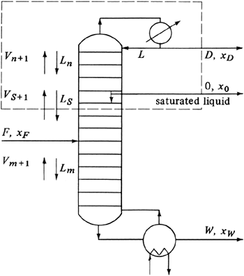
Making a total material balance on the top portion of the tower, as shown in the dashed-line box in Fig. 11.4-17,
Equation 11.4-33
![]()
where O is mol/h saturated liquid removed as a side stream. Since the liquid side stream is saturated,
Equation 11.4-34
![]()
Equation 11.4-35
![]()
Making a balance on the most volatile component,
Equation 11.4-36
![]()
Solving for yS+1, the operating line for the region between the side stream and the feed is
Equation 11.4-37
![]()
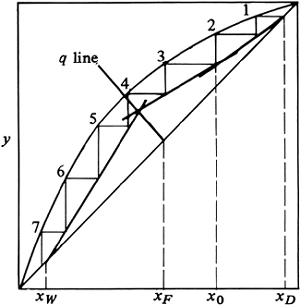
The slope of this line is LS/VS+1. The line can be located as shown in Fig. 11.4-18 by the q line, which determines the intersection of the stripping line and Eq. (11.4-37), or it may be fixed by the specification of xO, the side-stream composition. The step on the McCabe–Thiele diagram must be at the intersection of the two operating lines at xO in an actual tower. If this does not occur, the reflux ratio can be altered slightly to change the steps.
Figure 11.4-18. McCabe–Thiele plot for a tower with a liquid side stream above the feed.
5. Partial condensers
In a few cases it may be desired to remove the overhead distillate product as a vapor instead of a liquid. This can also occur when the low boiling point of the distillate makes complete condensation difficult. The liquid condensate in a partial condenser is returned to the tower as reflux and the vapor removed as product, as shown in Fig. 11.4-19.
Figure 11.4-19. Partial condenser where the vapor and liquid leave in equilibrium: (a) process flow diagram, (b) McCabe-Thiele plot.
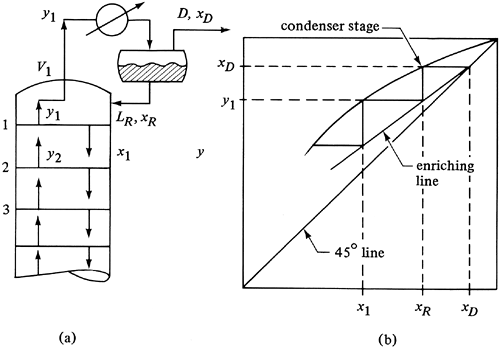
If the time of contact between the vapor product and the liquid is sufficient, the partial condenser is a theoretical stage. Then the composition xR of the liquid reflux is in equilibrium with the vapor composition yD, where yD = xD. If the cooling in the condenser is rapid and the vapor and liquid do not reach equilibrium, only a partial stage separation is obtained.


