6.6. NUMERICAL METHODS FOR STEADY-STATE MOLECULAR DIFFUSION IN TWO DIMENSIONS
6.6A. Derivation of Equations for Numerical Methods
1. Derivation of methods for steady state
In Fig. 6.6-1 a two-dimensional solid shown with unit thickness is divided into squares. The numerical methods for steady-state molecular diffusion are very similar to those for steady-state heat conduction discussed in Section 4.15. Hence, only a brief summary will be given here. The solid inside of a square is imagined to be concentrated at the center of the square at cn,m and is called a “node”, which is connected to adjacent nodes by connecting rods through which the mass diffuses.
Figure 6.6-1. Concentrations and spacing of nodes for two-dimensional steady-state molecular diffusion.

A total mass balance is made at steady state by stating that the sum of the molecular diffusion to the shaded area for unit thickness must equal zero:
Equation 6.6-1

where cn,m is concentration of A at node n,m in kg mol A/m3. Setting Δx = Δy, and rearranging,
Equation 6.6-2
![]()
2. Iteration method of numerical solution
In order to solve Eq. (6.6-2), a separate equation is written for each unknown point giving N linear algebraic equations for N unknown points. For a hand calculation using a modest number of nodes, the iteration method can be used to solve the equations, where the right-hand side of Eq. (6.6-2) is set equal to a residual ![]() :
:
Equation 6.6-3
![]()
Setting the equation equal to zero, ![]() = 0 for steady state and cn,m is calculated by
= 0 for steady state and cn,m is calculated by
Equation 6.6-4
![]()
Equations (6.6-3) and (6.6-4) are the final equations to be used to calculate all the concentrations at steady state.
Example 4.15-1 for steady-state heat conduction illustrates the detailed steps for the iteration method, which are identical to those for steady-state diffusion.
Once the concentrations have been calculated, the flux can be calculated for each element as follows. Referring to Fig. 6.6-1, the flux for the node or element cn,m to cn,m−1 is (Δx = Δy)
Equation 6.6-5

where the area A is Δx times 1 m deep and N is kg mol A/s. Equations are written for the other appropriate elements and the sum of the fluxes calculated. This numerical method is well suited for use with a computer spreadsheet.
6.6B. Equations for Special Boundary Conditions for Numerical Method
1. Equations for boundary conditions
When one of the nodal points cn,m is at a boundary where convective mass transfer is occurring to a constant concentration c∞ in the bulk fluid shown in Fig. 6.6-2a, a different equation must be derived. Making a mass balance on the node n, m, where mass in = mass out at steady state,
Equation 6.6-6

Figure 6.6-2. Different boundary conditions for steady-state diffusion: (a) convection at a boundary, (b) insulated boundary, (c) exterior corner with convective boundary, (d) interior corner with convective boundary.

where kc is the convective mass-transfer coefficient in m/s defined by Eq. (6.1-14).
Setting Δx = Δy, rearranging, and setting the resultant equation equal to ![]() , the residual, the following results:
, the residual, the following results:
For convection at a boundary (Fig. 6.6-2a),
Equation 6.6-7

This equation is similar to Eq. (4.15-16) for heat conduction and convection, with kc Δx/DAB being used in place of h Δx/k. Similarly, Eqs. (6.6-8)–(6.6-10) have been derived for the other boundary conditions shown in Fig. 6.6-2.
2. Boundary conditions with distribution coefficient
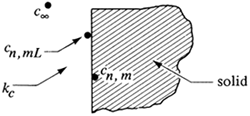
When Eq. (6.6-7) was derived, the distribution coefficient K between the liquid and the solid at the surface interface was 1.0. The distribution coefficient as shown in Fig. 6.6-3 is defined as
Equation 6.6-11
![]()
Figure 6.6-3. Interface concentrations for convective mass transfer at a solid surface and an equilibrium distribution coefficient K =×cn,mL/cn,m.

where cn,mL is the concentration in the liquid adjacent to the surface and cn,m is the concentration in the solid adjacent to the surface. Then in deriving Eq. (6.6-6), the right-hand side kc Δy(cn,m − c∞) becomes
Equation 6.6-12
![]()
where c∞ is the concentration in the bulk fluid. Substituting Kcn,m for cn,mL from Eq. (6.6-11) into (6.6-12) and multiplying and dividing by K,
Equation 6.6-13
![]()
Hence, whenever kc appears as in Eq. (6.6-7), Kkc should be substituted, and when c∞ appears, c∞/K should be used. Then Eq. (6.6-7) becomes as follows:
For convection at a boundary (Fig. 6.6-2a),
Equation 6.6-14

Equations (6.6-9) and (6.6-10) can be rewritten in a similar manner as follows:
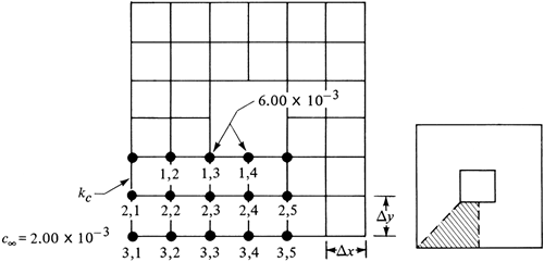
EXAMPLE 6.6-1. Numerical Method for Convection and Steady-State DiffusionFor the two-dimensional hollow solid chamber shown in Fig. 6.6-4, determine the concentrations at the nodes as shown at steady state. At the inside surfaces the concentrations remain constant at 6.00 × 10⁻³ kg mol/m3. At the outside surfaces the convection coefficient kc = 2 × 10⁻⁷ m/s and c∞ = 2.00 × 10⁻³ kg mol/m3. The diffusivity in the solid is DAB = 1.0 × 10⁻⁹ m2/s. The grid size is Δx = Δy = 0.005 m. Also, determine the diffusion rates per 1.0 m depth. The distribution coefficient K = 1.0. Figure 6.6-4. Concentrations for hollow chamber for Example 6.6-1.
Solution:
To simplify the calculations, all the concentrations will be multiplied by 103. Since the chamber is symmetrical, we do the calculations on the For the interior points c2,2, c2,3, and c2,4 we use Eqs. (6.6-3) and (6.6-4); for the corner convection point c3,1, Eq. (6.6-9); for the other convection points c3,2, c3,3, c3,4, Eq. (6.6-7). The term kc Δx/DAB = (2 × 10⁻⁷)(0.005)/(1.0 × 10−9) = 1.00. First approximation.
Starting with c2,2 we use Eq. (6.6-3) and calculate the residual
Hence, c2,2 is not at steady state. Next we set
This new value of c2,2 replaces the old value. For c2,3,
For c2,4,
For c3,1, we use Eq. (6.6-9):
Setting Eq. (6.6-9) equal to zero and solving for c3,1,
For c3,2, we use Eq. (6.6-7):
For c3,3,
For c3,4,
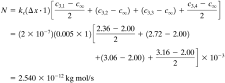
Having completed one sweep across the grid map, we can perform a second approximation using the new values calculated, starting with c2,2 or any other node. We continue until all the residuals are as small as desired. The final values after three approximations are c2,2 = 3.47, c2,3 = 4.24, c2,4 = 4.41, c3,1 = 2.36, c3,2 = 2.72, c3,3 = 3.06, c3,4 = 3.16. To calculate the diffusion rates we first calculate the total convective diffusion rate, leaving the bottom surface at nodes c3,1, c3,2, c3,3, and c3,4 for 1.0 m depth:
Note that the first and fourth paths include only one-half of a surface. Next we calculate the total diffusion rate in the solid entering the top surface inside, using an equation similar to Eq. (6.6-5):
At steady state the diffusion rate leaving by convection should equal that entering by diffusion. These results indicate a reasonable check. Using smaller grids would give even more accuracy. Note that the results for the diffusion rate should be multiplied by 8.0 for the whole chamber. |


