3.2. MEASUREMENT OF FLOW OF FLUIDS
It is important to be able to measure and control the amount of material entering and leaving a chemical or other processing plant. Since many of the materials are in the form of fluids, they are flowing in pipes or conduits. Many different types of devices are used to measure the flow of fluids. The simplest are those that measure directly the volume of the fluids, such as ordinary gas and water meters and positive-displacement pumps. Current meters make use of an element, such as a propeller or cups on a rotating arm, which rotates at a speed determined by the velocity of the fluid passing through it. Very widely used for fluid metering are the pitot tube, venturi meter, orifice meter, and open-channel weirs.
3.2A. Pitot Tube
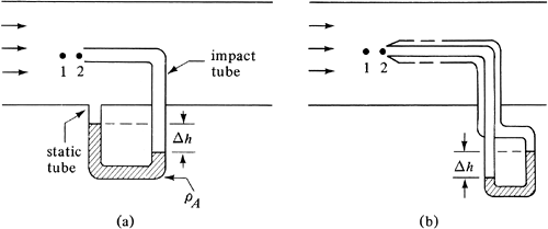
The pitot tube is used to measure the local velocity at a given point in the flow stream and not the average velocity in the pipe or conduit. In Fig. 3.2-1a, a sketch of this simple device is shown. One tube, the impact tube, has its opening normal to the direction of flow, while the static tube has its opening parallel to the direction of flow.
Figure 3.2-1. Diagram of pitot tube: (a) simple tube, (b) tube with static pressure holes.

The fluid flows into the opening at point 2; pressure builds up and then remains stationary at this point, called the stagnation point. The difference in the stagnation pressure at point 2 and the static pressure measured by the static tube represents the pressure rise associated with deceleration of the fluid. The manometer measures this small pressure rise. If the fluid is incompressible, we can write the Bernoulli equation (2.7-32) between point 1, where the velocity ν1 is undisturbed before the fluid decelerates, and point 2, where the velocity ν2 is zero:
Equation 3.2-1

Setting ν2 = 0 and solving for ν1,
Equation 3.2-2
![]()
where ν is the velocity v1 in the tube at point 1 in m/s, p2 is the stagnation pressure, ρ is the density of the flowing fluid at the static pressure p1, and Cp is a dimensionless coefficient to take into account deviations from Eq. (3.2-1) that generally varies between about 0.98 and 1.0. For accurate use, the coefficient should be determined by calibration of the pitot tube. This equation applies to incompressible fluids but can be used to approximate the flow of gases at moderate velocities and pressure changes of about 10% or less of the total pressure. For gases the pressure change is often quite low and, hence, accurate measurement of velocities is difficult.
The value of the pressure drop p2 - p1 or Δp in Pa is related to Δh, the reading on the manometer, by Eq. (2.2-14) as follows:
Equation 3.2-3
![]()
where ρA is the density of the fluid in the manometer in kg/m3 and Δh is the manometer reading in m. In Fig. 3.2-1b, a more compact design is shown with concentric tubes. In the outer tube, static pressure holes are parallel to the direction of flow. Further details are given elsewhere (P1).
Since the pitot tube measures velocity at only one point in the flow, several methods can be used to obtain the average velocity in the pipe. In the first method the velocity is measured at the exact center of the tube to obtain νmax. Then by using Fig. 2.10-2, the νav can be obtained. Care should be taken to have the pitot tube at least 100 diameters downstream from any pipe obstruction. In the second method, readings are taken at several known positions in the pipe cross section and then, using Eq. (2.6-17), a graphical or numerical integration is performed to obtain νav.
EXAMPLE 3.2-1. Flow Measurement Using a Pitot TubeA pitot tube similar to Fig. 3.2-1a is used to measure the airflow in a circular duct 600 mm in diameter. The flowing air temperature is 65.6°C. The pitot tube is placed at the center of the duct and the reading Δh on the manometer is 10.7 mm of water. A static-pressure measurement obtained at the pitot tube position is 205 mm of water above atmospheric. The pitot-tube coefficient Cp = 0.98.
Solution: For part (a), the properties of air at 65.6°C. from Appendix A.3 are μ = 2.03 × 10⁻⁵ Pa · s, ρ = 1.043 kg/m3 (at 101.325 kPa). To calculate the absolute static pressure, the manometer reading Δh = 0.205 m of water indicates the pressure above 1 atm abs. Using Eq. (2.2-14), the water density as 1000 kg/m3, and assuming 1.043 kg/m3 as the air density,
Then the absolute static pressure p1 = 1.01325 × 10⁵ + 0.02008 × 105 = 1.0333 × 10⁵ Pa. The correct air density in the flowing air is (1.0333 × 10⁵/1.01325 × 105)(1.043) = 1.063 kg/m3. This correct value, when used instead of 1.043, would have a negligible effect on the recalculation of p1. To calculate Δp for the pitot tube, Eq. (3.2-3) is used:
Using Eq. (3.2-2), the maximum velocity at the center is
The Reynolds number, using the maximum velocity, is
From Fig. 2.10-2, νav/νmax = 0.85. Then, νav = 0.85(13.76) = 11.70 m/s. To calculate the flow rate for part (b), the cross-sectional area of the duct, A = (π/4)(0.600)2 = 0.2827 m2. The flow rate = 0.2827(11.70) = 3.308 m3/s. |
3.2B. Venturi Meter
A venturi meter, shown in Fig. 3.2-2, is usually inserted directly into a pipeline. A manometer or other device is connected to the two pressure taps shown and measures the pressure difference p1 − p2 between points 1 and 2. The average velocity at point 1 where the diameter is D1 m is ν1 m/s, and at point 2 or the throat the velocity is ν2 and the diameter D2. Since the narrowing down from D1 to D2 and the expansion from D2 back to D1 is gradual, little frictional loss due to contraction and expansion is incurred.
Figure 3.2-2. Venturi flow meter.

To derive the equation for the venturi meter, friction is neglected and the pipe is assumed horizontal. Assuming turbulent flow and writing the mechanical-energy-balance equation (2.7-28) between points 1 and 2 for an incompressible fluid,
Equation 3.2-4
![]()
The continuity equation for constant p is
Equation 3.2-5
![]()
Combining Eqs. (3.2-4) and (3.2-5) and eliminating ν1,
Equation 3.2-6

To account for the small friction loss, an experimental coefficient Cν is introduced to give
Equation 3.2-7

This holds for liquids and very small pressure drops in gases of less than 1%. For many meters and a Reynolds number >104 at point 1, Cν is about 0.98 for pipe diameters below 0.2 m and 0.99 for larger sizes. However, these coefficients can vary, and individual calibration is recommended if the manufacturer's calibration is not available.
To calculate the volumetric flow rate, the velocity ν2 is multiplied by the area A2:
Equation 3.2-8
![]()
For the measurement of compressible flow of gases, the adiabatic expansion from p1 to p2 pressure must be allowed for in Eq. (3.2-7). A similar equation and the same coefficient Cν are used along with the dimensionless expansion correction factor Y (shown in Fig. 3.2-3 for air) as follows:
Equation 3.2-9

Figure 3.2-3. Expansion factor for air in venturi, flow nozzle, and orifice. [Calculated from equations and data in references (A2, M2, S3).]

where m is flow rate in kg/s, ρ1 is density of the fluid upstream at point 1 in kg/m3, and A2 is cross-sectional area at point 2 in m2.
The pressure difference p1 − p2 occurs because the velocity is increased from ν1 to ν2. However, farther down the tube the velocity returns to its original value of ν1 for liquids. Because of frictional losses, some of the difference p1 − p2 is not fully recovered downstream to the original p1. In a properly designed venturi meter, the permanent loss is about 10% of the differential p1 − p2, and this represents power loss. A venturi meter is often used to measure flows in large lines, such as city water systems.
3.2C. Orifice Meter
For ordinary installations in a process plant the venturi meter has several disadvantages. It occupies a lot of space and is expensive. Also, the throat diameter is fixed, so that if the flow-rate range is changed considerably, inaccurate pressure differences may result. The orifice meter overcomes these objections but at the price of a much larger permanent head or power loss.
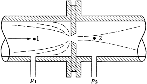
A typical sharp-edged orifice is shown in Fig. 3.2-4. A machined and drilled plate having a hole of diameter D0 is mounted between two flanges in a pipe of diameter D1. Pressure taps at points 1 upstream and 2 downstream measure p1 − p2. The exact positions of the two taps are somewhat arbitrary: in one type of meter the taps are installed about 1 pipe diameter upstream and 0.3 to 0.8 pipe diameter downstream. The fluid stream, once past the orifice plate, forms a vena contracta or free-flowing jet.
Figure 3.2-4. Orifice flow meter.

The equation for the orifice is similar to Eq. (3.2-7):
Equation 3.2-10

where ν0 is the velocity in the orifice in m/s, D0 is the orifice diameter in m, and C0 is the dimensionless orifice coefficient. The orifice coefficient C0 is always determined experimentally. If the NRe at the orifice is above 20000 and D0/D1 is less than about 0.5, the value of C0 is approximately constant and has the value 0.61, which is adequate for design for liquids or gases (M2, P1). Below 20000 the coefficient rises sharply and then drops, and a correlation for C0 is given elsewhere (P1).
As in the case of the venturi, for the measurement of compressible flow of gases in an orifice, a correction factor Y given in Fig. 3.2-3 for air is used as follows:
Equation 3.2-11
![]()
where m is flow rate in kg/s, ρ1 is upstream density in kg/m3, and A0 is the cross-sectional area of the orifice. For liquids, Y is 1.0.
The permanent pressure loss is much higher than for a venturi because of the eddies formed when the jet expands below the vena contracta. This loss depends on D0/D1 and is as follows:
Equation 3.2-12
![]()
where β = D0/D1 (P1) and p4 is the fully recovered pressure 4 -8 pipe diameters downstream. For β = ![]() , this power loss is 75% of p1
- p2.
, this power loss is 75% of p1
- p2.
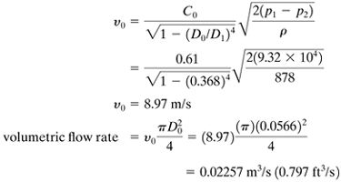
EXAMPLE 3.2-2. Metering Oil Flow by an OrificeA sharp-edged orifice having a diameter of 0.0566 m is installed in a 0.1541-m pipe through which oil having a density of 878 kg/m3 and a viscosity of 4.1 cp is flowing. The measured pressure difference across the orifice is 93.2 kN/m2. Calculate the volumetric flow rate in m3/s. Assume that C0 = 0.61. Solution:
Substituting into Eq. (3.2-10).
The NRe is calculated see if it is greater than 2 × 10⁴ for C0 = 0.61:
Hence, the Reynolds number is above 2 × 10⁴. |
3.2D. Flow-Nozzle Meter
A typical flow nozzle is shown in Fig. 3.2-5. It is essentially a short cylinder with the approach being elliptical in shape. This meter has characteristics similar to those of the venturi meter but is shorter and much less expensive. The length of the straight portion of the throat is about one-half the diameter of the throat, D2. The upstream pressure tap p1 is 1 pipe diameter from the inlet-nozzle face, and the downstream tap p2 is ![]() pipe diameter from the inlet-nozzle face.
pipe diameter from the inlet-nozzle face.
Figure 3.2-5. Flow-nozzle meter.

The equation for flow for liquids is the same as Eq. (3.2-7) for the venturi, with the coefficient Cn for the flow nozzle replacing Cv for the venturi. Also, the equation for compressible flow of gases for the flow nozzle is the same as Eq. (3.2-9) for the venturi, with the coefficient Cn. The expansion factor Y is the same for the flow nozzle and the venturi.
For the flow nozzle the coefficient Cn ranges from 0.95 at a pipe Reynolds number of 104, 0.98 at 105, and 0.99 at 106 or above (P1, S3). The permanent pressure loss (p1 − p4) is as follows, where p4 is the final, fully recovered downstream pressure:
Equation 3.2-13
![]()
where β = D2/D1. This loss is greater than that for venturi meters and less than that for orifice meters. For β =
![]() , this power loss is 60% of p1 − p2.
, this power loss is 60% of p1 − p2.
3.2E. Variable-Area Flow Meters (Rotameters)
In Fig. 3.2-6 a variable-area flow meter is shown. The fluid enters at the bottom of the tapered glass tube, flows through the annular area around the tube, and exits at the top. The float remains stationary. The differential head or pressure drop is held constant. At a higher flow rate the float rises and the annular area increases to keep a constant pressure drop. The height of rise in the tube is calibrated with the flow rate, and the relation between the meter reading and the flow rate is approximately linear.
Figure 3.2-6. Rotameter: (a) flow diagram with glass tube, (b) spherical float, (c) viscosity-insensitive float.

For a given float of density pf and a fluid density ρA, the mass flow rate mA is given by
Equation 3.2-14

where qA, volumetric flow rate, is the reading on the rotameter, and K is a constant which is determined experimentally. If a fluid ρB is used instead of ρA, at the same height or reading of qA on the rotameter and assuming K does not vary appreciably, the following approximation can be used:
Equation 3.2-15

For gases where ρf ≫ ρA and ρB,
![]() Note that the reading on the rotameter is taken at the highest and widest point of the float.
Note that the reading on the rotameter is taken at the highest and widest point of the float.
3.2F. Other Types of Flow Meters
Many other types of flow meters are available; the more important ones are discussed briefly as follows:
1. Turbine- and paddle-wheel meters
A turbine wheel or a paddle wheel is placed inside a pipe, and the rotary speed depends on the flow rate of the fluid. Residential and industrial gas and water meters are often of the rotary wheel type.
2. Thermal-gas mass flow meters
Gas flowing in a tube is divided into a constant ratio because of laminar flow into a main stream and a small stream in a sensor tube. A small but constant amount of heat is added to the sensor tube flow. By measuring the temperature rise, the output temperature rise can be related to the gas mass flow rate. These meters are mass flow meters and are unaffected by temperature and pressure.
3. Magnetic flow meters
A magnetic field is generated across the conductive fluid flowing in a pipe. Using Faraday's law of electromagnetic inductance, the induced voltage is directly proportional to the flow velocity (D3). The meter is insensitive to changes in density and viscosity. The meter cannot be used with most hydrocarbons because of their low conductivity.
4. Coriolis mass flow meter
This meter is insensitive to operating conditions of viscosity, density, type of fluid, and slurries. Fluid from the main flow enters two U-tube side channels (D3). The fluid induces a Coriolis force according to Newton's second law. The tubes then twist slightly, and the measured twist angle is proportional to the mass flow rate.
5. Vortex-shedding flow meter
When a fluid flows past a blunt object, the fluid forms vortices or eddies (D3). The vortices are counted and the signal is proportional to the flow rate.
3.2G. Flow in Open Channels and Weirs
In many instances in process engineering and in agriculture, liquids are flowing in open channels rather than closed conduits. To measure the flow rates, weir devices are often used. A weir is a dam over which the liquid flows. The two main types of weirs are the rectangular weir and the triangular weir shown in Fig. 3.2-7. The liquid flows over the weir, and the height h0 (weir head) in m is measured above the flat base or the notch as shown. This head should be measured at a distance of about 3h0 m upstream of the weir by a level or float gage.
Figure 3.2-7. Types of weirs: (a) rectangular, (b) triangular.

The equation for the volumetric flow rate q in m3/s for a rectangular weir is given by
Equation 3.2-16
![]()
where L = crest length in m, g = 9.80665 m/s2, and h0 = weir head in m. This is called the modified Francis weir formula and it agrees with experimental values within 3% if L > 2h0, velocity upstream < 0.6 m/s, h0 > 0.09 m, and the height of the crest above the bottom of the channel > 3h0. In English units L and h are in ft, q in ft3/s, and g = 32.174 ft/s2.
For the triangular notch weir,
Equation 3.2-17
![]()
Both Eqs. (3.2-16) and (3.2-17) apply only to water. For other liquids, see data given elsewhere (P1).


