2.8. OVERALL MOMENTUM BALANCE
2.8A. Derivation of General Equation
A momentum balance can be written for the control volume shown in Fig. 2.6-3 which is somewhat similar to the overall mass-balance equation. Momentum, in contrast to mass and energy, is a vector quantity. The total linear momentum vector P of the total mass M of a moving fluid having a velocity of v is
Equation 2.8-1
![]()
The term Mv is the momentum of this moving mass M enclosed at a particular instant in the control volume shown in Fig. 2.6-4. The units of Mν are kg · m/s in the SI system.
Starting with Newton's second law, we will develop the integral momentum-balance equation for linear momentum. Angular momentum will not be considered here. Newton's law may be stated: The time rate of change of momentum of a system is equal to the summation of all forces acting on the system and takes place in the direction of the net force:
Equation 2.8-2
![]()
where F is force. In the SI system F is in newtons (N) and 1 N = 1 kg · m/s2. Note that in the SI system gc is not needed, but it is needed in the English system.
The equation for the conservation of momentum with respect to a control volume can be written as follows:
Equation 2.8-3

This is in the same form as the general mass-balance equation (2.6-3), with the sum of the forces as the generation rate term. Hence, momentum is not conserved, since it is generated by external forces on the system. If external forces are absent, momentum is conserved.
Using the general control volume shown in Fig. 2.6-4, we shall evaluate the various terms in Eq. (2.8-3), using methods very similar to the development of the general mass balance. For a small element of area dA on the control surface, we write
Equation 2.8-4
![]()
Note that the rate of mass efflux is (ρν)(dA cos α). Also, note that (dA cos α) is the area dA projected in a direction normal to the velocity vector ν, and α is the angle between the velocity vector ν and the outward-directed-normal vector n. From vector algebra the product in Eq. (2.8-4) becomes
Equation 2.8-5
![]()
Integrating over the entire control surface A,
Equation 2.8-6
![]()
The net efflux represents the first two terms on the right-hand side of Eq. (2.8-3).
Similarly to Eq. (2.6-5), the rate of accumulation of linear momentum within the control volume V is
Equation 2.8-7

Substituting Equations (2.8-2), (2.8-6), and (2.8-7) into (2.8-3), the overall linear momentum balance for a control volume becomes
Equation 2.8-8

We should note that Σ F in general may have a component in any direction, and that F is the force the surroundings exert on the control-volume fluid. Since Eq. (2.8-8) is a vector equation, we may write the component scalar equations for the x, y, and z directions:
Equation 2.8-9

Equation 2.8-10

Equation 2.8-11

The force term Σ Fx in Eq. (2.8-9) is composed of the sum of several forces. These are given as follows:
Pressure force. The force Fxp is the x-directed force caused by the pressure forces acting on the surface of the fluid system. When the control surface cuts through the fluid, the pressure is taken to be directed inward and perpendicular to the surface. In some cases part of the control surface may be a solid, and this wall is included inside the control surface. Then there is a contribution to Fxp from the pressure on the outside of this wall, which typically is atmospheric pressure. If gage pressure is used, the integral of the constant external pressure over the entire outer surface can be automatically ignored.
Friction force. When the fluid is flowing, an x-directed shear or friction force Fxs is present, which is exerted on the fluid by a solid wall when the control surface cuts between the fluid and the solid wall. In some or many cases, this frictional force may be negligible compared to the other forces and is neglected.
Solid surface force. In cases where the control surface cuts through a solid, there is present force Rx, which is the x component of the resultant of the forces acting on the control volume at these points. This occurs typically when the control volume includes a section of pipe and the fluid it contains. This is the force exerted by the solid surface on the fluid.
The force terms of Eq. (2.8-9) can then be represented as
Equation 2.8-12
![]()
Similar equations can be written for the y and z directions. Then Eq. (2.8-9) becomes, for the x direction,
Equation 2.8-13

2.8B. Overall Momentum Balance in Flow System in One Direction
A quite common application of the overall momentum-balance equation is the case of a section of a conduit with its axis in the x direction. The fluid will be assumed to be flowing at steady state in the control volume shown in Fig. 2.6-3 and in Fig. 2.8-1. Since ν = νx, Eq. (2.8-13) for the x direction becomes as follows:
Equation 2.8-14
![]()
Figure 2.8-1. Flow through a horizontal nozzle in the x direction only.

Integrating, with cos α = ±1.0 and ρA = m/νav,
Equation 2.8-15

where, if the velocity is not constant and varies across the surface area,
Equation 2.8-16

The ratio ![]() is replaced by νxav/β where β, which is the momentum velocity correction factor, has a value of 0.95 to 0.99 for turbulent flow and
is replaced by νxav/β where β, which is the momentum velocity correction factor, has a value of 0.95 to 0.99 for turbulent flow and ![]() for laminar flow. For most applications in turbulent flow,
for laminar flow. For most applications in turbulent flow, ![]() is replaced by νx
av, the average bulk velocity. Note that the subscript x on νx and Fx can be dropped, since νx = ν and Fx = F for one-directional flow.
is replaced by νx
av, the average bulk velocity. Note that the subscript x on νx and Fx can be dropped, since νx = ν and Fx = F for one-directional flow.
The term Fxp, which is the force caused by the pressures acting on the surface of the control volume, is
Equation 2.8-17
![]()
The friction force will be neglected in Eq. (2.8-15), so Fxs = 0. The body force Fxg = 0 since gravity is acting only in the y direction. Substituting Fxp from Eq. (2.8-17) into (2.8-15), replacing ![]() by ν/β (where νx
av = ν), setting β = 1.0, and solving for Rx in Eq. (2.8-15),
by ν/β (where νx
av = ν), setting β = 1.0, and solving for Rx in Eq. (2.8-15),
Equation 2.8-18
![]()
where Rx is the force exerted by the solid on the fluid. The force of the fluid on the solid (reaction force) is the negative of this, or −Rx.
EXAMPLE 2.8-1. Momentum Velocity Correction Factor β for Laminar FlowThe momentum velocity correction factor β is defined as follows for flow in one direction, where the subscript x is dropped: Equation 2.8-19
Equation 2.8-20
Determine β for laminar flow in a tube. Solution: Using Eq. (2.8-16), Equation 2.8-21
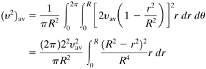
Substituting Eq. (2.7-16) for laminar flow into Eq. (2.8-21) and noting that A = πR2 and dA = r dr dθ, we obtain (see Example 2.6-3) Equation 2.8-22
Integrating Eq. (2.8-22) and rearranging, Equation 2.8-23
Substituting Eq. (2.8-23) into (2.8-20), β = |
EXAMPLE 2.8-2. Momentum Balance for Horizontal NozzleWater is flowing at a rate of 0.03154 m3/s through a horizontal nozzle shown in Fig. 2.8-1 and discharges to the atmosphere at point 2. The nozzle is attached at the upstream end at point 1 and frictional forces are considered negligible. The upstream ID is 0.0635 m and the downstream 0.0286 m. Calculate the resultant force on the nozzle. The density of the water is 1000 kg/m3. Solution: First, the mass flow and average or bulk velocities at points 1 and 2 are calculated. The area at point 1 is A1 = (π/4)(0.0635)2 = 3.167 × 10⁻³ m2 and A2 = (π/4)(0.0286)2 = 6.424 × 10⁻⁴ m2. Then,
The velocity at point 1 is ν1 = 0.03154/(3.167 × 10−3) = 9.96 m/s, and ν2 = 0.03154/(6.424 × 10−4) = 49.1 m/s. To evaluate the upstream pressure p1 we use the mechanical-energy-balance equation (2.7-28) assuming no frictional losses and turbulent flow. (This can be checked by calculating the Reynolds number.) This equation then becomes, for α = 1.0, Equation 2.8-24
Setting p2 = 0 gage pressure, ρ = 1000 kg/m3, ν1 = 9.96 m/s, ν2 = 49.1 m/s, and solving for p1,
For the x direction, the momentum-balance equation (2.8-18) is used. Substituting the known values and solving for Rx,
Since the force is negative, it is acting in the negative x direction, or to the left. This is the force of the nozzle on the fluid. The force of the fluid on the solid is −Rx, or +2427 N. |
2.8C. Overall Momentum Balance in Two Directions
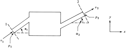
Another application of the overall momentum balance is shown in Fig. 2.8-2 for a flow system with fluid entering a conduit at point 1 inclined at an angle of α1 relative to the horizontal x direction and leaving a conduit at point 2 at an angle α2. The fluid will be assumed to be flowing at steady state and the frictional force Fxs will be neglected. Then Eq. (2.8-13) for the x direction becomes as follows for no accumulation:
Equation 2.8-25

Figure 2.8-2. Overall momentum balance for flow system with fluid entering at point 1 and leaving at 2.

Integrating the surface (area) integral,
Equation 2.8-26
![]()
The term (ν2)av/νav can again be replaced by νav/β, with β being set at 1.0. From Fig. 2.8-2, the term Fxp is
Equation 2.8-27
![]()
Then Eq. (2.8-26) becomes as follows after solving for Rx:
Equation 2.8-28
![]()
The term Fxg = 0 in this case.
For Ry the body force Fyg is in the negative y direction and Fyg = −mtg, where mt is the total mass fluid in the control volume. Replacing cos α by sin α, the equation for the y direction becomes
Equation 2.8-29
![]()
EXAMPLE 2.8-3. Momentum Balance in a Pipe BendFluid is flowing at steady state through a reducing pipe bend, as shown in Fig. 2.8-3. Turbulent flow will be assumed with frictional forces negligible. The volumetric flow rate of the liquid and the pressure p2 at point 2 are known, as are the pipe diameters at both ends. Derive the equations to calculate the forces on the bend. Assume that the density ρ is constant. Figure 2.8-3. Flow through a reducing bend in Example 2.8-3.
Solution: The velocities ν1 and ν2 can be obtained from the volumetric flow rate and the areas. Also, m = ρ1ν1A1 = ρ2ν2A2. As in Example 2.8-2, the mechanical-energy-balance equation (2.8-24) is used to obtain the upstream pressure, p1. For the x direction, Eq. (2.8-28) is used for the momentum balance. Since α1 = 0°, cos α1 = 1.0. Equation (2.8-28) becomes Equation 2.8-30
For the y direction, the momentum-balance equation (2.8-29) is used, where sin α1 = 0: Equation 2.8-31
where mt is total mass fluid in the pipe bend. The pressures at points 1 and 2 are gage pressures since the atmospheric pressures acting on all surfaces cancel. The magnitude of the resultant force of the bend acting on the control volume fluid is Equation 2.8-32
The angle this makes with the vertical is θ = arctan(Rx/Ry). Often the gravity force Fyg is small compared to the other terms in Eq. (2.8-31) and is neglected. |
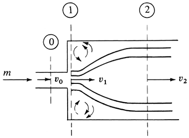
EXAMPLE 2.8-4. Friction Loss in a Sudden EnlargementA mechanical-energy loss occurs when a fluid flows from a small pipe to a large pipe through an abrupt expansion, as shown in Fig. 2.8-4. Use the momentum balance and mechanical-energy balance to obtain an expression for the loss for a liquid. (Hint: Assume that p0 = p1 and ν0 = ν1. Make a mechanical-energy balance between points 0 and 2 and a momentum balance between points 1 and 2. It will be assumed that p1 and p2 are uniform over the cross-sectional area.) Figure 2.8-4. Losses in expansion flow.
Solution: The control volume is selected so that it does not include the pipe wall and Rx drops out. The boundaries selected are points 1 and 2. The flow through plane 1 occurs only through an area A0. The frictional drag force will be neglected, and all the loss is assumed to be from eddies in this volume. Making a momentum balance between points 1 and 2 using Eq. (2.8-18) and noting that p0 = p1, ν1 = ν0, and A1 = A2, Equation 2.8-33
The mass flow rate is m = ν0ρA0 and ν2 = (A0/A2)ν0. Substituting these terms into Eq. (2.8-33) and rearranging gives us Equation 2.8-34
Applying the mechanical-energy-balance equation (2.7-28) to points 1 and 2, Equation 2.8-35
Finally, combining Eqs. (2.8-34) and (2.8-35), Equation 2.8-36
|
2.8D. Overall Momentum Balance for Free Jet Striking a Fixed Vane
When a free jet impinges on a fixed vane as in Fig. 2.8-5, the overall momentum balance can be applied to determine the force on the smooth vane. Since there are no changes in elevation or pressure before and after impact, there is no loss in energy, and application of the Bernoulli equation shows that the magnitude of the velocity is unchanged. Losses due to impact are neglected. The frictional resistance between the jet and the smooth vane is also neglected. The velocity is assumed to be uniform throughout the jet upstream and downstream. Since the jet is open to the atmosphere, the pressure is the same at all ends of the vane.
Figure 2.8-5. Free jet impinging on a fixed vane: (a) smooth, curved vane, (b) smooth, flat vane.

In making a momentum balance for the control volume shown for the curved vane in Fig. 2.8-5a, Eq. (2.8-28) is written as follows for steady state, where the pressure terms are zero, ν1 = ν2, A1 = A2, and m = ν1A1ρ1 = ν2A2ν2:
Equation 2.8-37
![]()
Using Eq. (2.8-29) for the y direction and neglecting the body force,
Equation 2.8-38
![]()
Hence, Rx and Ry are the force components of the vane on the control volume fluid. The force components on the vane are −Rx and −Ry.
EXAMPLE 2.8-5. Force of Free Jet on a Curved, Fixed VaneA jet of water having a velocity of 30.5 m/s and a diameter of 2.54 × 10⁻² m is deflected by a smooth, curved vane as shown in Fig. 2.8-5a, where α2 = 60°. What is the force of the jet on the vane? Assume that ρ = 1000 kg/m3. Solution: The cross-sectional area of the jet is A1 = π(2.54 × 10⁻²)2/4 = 5.067 × 10⁻⁴ m2. Then, m = ν1A1ρ1 = 30.5 × 5.067 × 10−4 × 1000 = 15.45 kg/s. Substituting into Eqs. (2.8-37) and (2.8-38),
The force on the vane is −Rx = +235.6 N and −Ry = −408.1 N. The resultant force is calculated using Eq. (2.8-32). |
In Fig. 2.8-5b a free jet at velocity ν1 strikes a smooth, inclined flat plate and the flow divides into two separate streams whose velocities are all equal (ν1 = ν2 = ν3) since there is no loss in energy. It is convenient to make a momentum balance in the p direction parallel to the plate. No force is exerted on the fluid by the flat plate in this direction; that is, there is no tangential force. Then, the initial momentum component in the p direction must equal the final momentum component in this direction. This means Σ F p = 0. Writing an equation similar to Eq. (2.8-26), where m1 is kg/s entering at 1 and m2 leaves at 2 and m3 at 3,
Equation 2.8-39

Equation 2.8-40
![]()
Combining and solving,
Equation 2.8-41
![]()
The resultant force exerted by the plate on the fluid must be normal to it. This means the resultant force is simply m1ν1 sin α2. Alternatively, the resultant force on the fluid can be calculated by determining Rx and Ry from Eqs. (2.8-28) and (2.8-29) and then using Eq. (2.8-32). The force on the bend is the opposite of this.


