Chapter 6
A Biomechanical Character
In this chapter, we will depart from working with more organic forms and examine how to conceptualize and create a more machined or manufactured shape. ZBrush typically lends itself to working out organic shapes quickly and intuitively. This presents a problem when the design called for industrial shapes, which are obviously manufactured.
In this chapter, we will execute a biomechanical design using some of the new hard surface and form sketching tools available since ZBrush 4.0. ZBrush includes an entire suite of brushes intended to let the artist sketch mechanical shapes much in the same way they might sketch organic forms. This has opened a new vista for using ZBrush as a concept design tool because it frees designers to explore industrial forms in 3-D freely, when before such form exploration would require the planned, careful use of Maya. Until now it was difficult, if not impossible, to “sketch” 3-D form explorations of hard surface models with any degree of accuracy without a high degree of expertise in polygon or NURBS modeling. We will explore tools like the Planar brushes, Clip brushes, Shadowbox, and we will even incorporate Maya into your workflow with GoZ.
The purpose of this chapter is to illustrate how mechanical forms can be quickly conceptualized using the right combination of tools. By taking this approach, you can avoid the “modeling quagmire,” where you are too busy worrying about proper edgeflow and polygon geometry to be freely creative.
As we work through this character, I also want to show the considerations that went into this particular design. His mechanical structures are based firmly on human physiology, and I attempt to use interesting shape combinations, contrast between organic and mechanical forms, and a strong silhouette with interesting use of negative spaces. I want to show how I consider all these topics to help create an interesting character design.
The Brief: Biomechanical Character
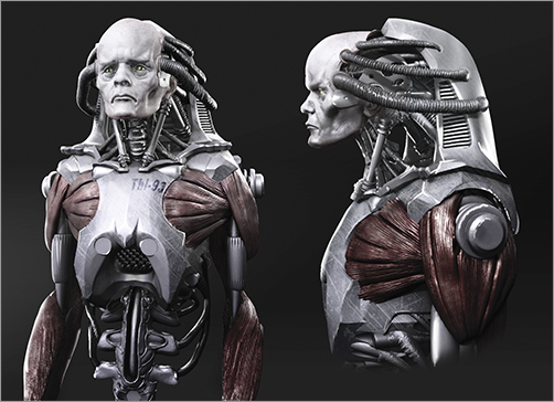
The brief for this character is a human-machine hybrid—a cyborg—with more mechanical parts than human. The robotic anatomy should mirror the form and functionality of the human skeleton and muscle system with flesh incorporated into the mechanical structure. The design should have a laboratory feel, meaning this is not a finished “showroom ready” robot but rather a prototype with some exposed elements. It should appear to have been constructed from parts in a lab. I want the character to have a strong mass of an upper body to denote a core strength, but I thought more spindly or skinned arms might be an interesting contrast. Most importantly, I wanted to explore the use of negative spaces in unexpected areas to drive home that this is not a man in a suit but rather human parts grafted into a mechanical structure.
We will now begin the process of bringing our biomechanical character to digital design. I will begin by pulling some elements from my library of shapes. After a short time working in ZBrush, you will develop a back catalog of old designs, sculptures, and forms that sit on your hard drive. Don’t be afraid to revisit and reuse these for other projects. Speed is one of the keys in concept design—you must produce strong ideas but you need to do them fast. By taking advantage of your shape library, you will always be able to cut down on time and quickly reform an old part into something entirely new. As we work on the rest of the body, we will try to relate shapes back to human anatomical forms. This is for two reasons. Firstly, we want to engage audience recognition of humanoid forms within this cyborg creature. Secondly, the design of a robot will tend to follow the same biomechanics as the human body. This is simply because the human machine is time tested and well designed. It tends to be the point of departure for robotics designers. When we create structures like the shoulder apparatus, we will be using the actual shoulder girdle of the human skeleton as a reference point.
Creating the Head
In this case, I will use the basic head we created from a Polysphere in my book ZBrush Creature Creation. We will use this as the base to sculpt the cyborg’s face. As you follow this tutorial, be aware this is a very involved process, which I have documented fully on video. I have highlighted steps here to call attention to some of the most important parts of the process. Be sure to watch the complete video of the process supplied on the DVD or download files to get the most from this lesson.
Negative Spaces
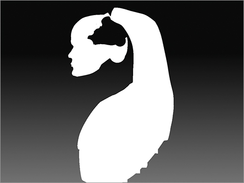
Negative spaces are those areas between shapes. Here you see the white shapes are distinct from the spaces in black. I have inverted the color in two distinct images to help you see the two different shapes (the positive and negative). Notice how both create interesting shapes that define the overall look. These negative shapes are often just as important as the shape of the figure itself. We see both when we observe an object and the negative spaces can either help reinforce or detract from the design, depending on how they are treated. In life drawing and sculpture, when artists work from a model, they are taught to observe the negative space to help understand the actual form or outer contour of the figure. By always being aware of what you are saying with both your shapes and the negative space around your shapes, you are exerting more control over the effect of your design. You can see how both positive and negative shapes can be interesting.
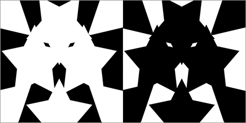
For this character, I want to let the negative spaces infringe on areas where the viewer will expect there to be body. By knocking out negative space behind the head or in the waist, it creates a surprise for the viewer. They register a humanoid form but one with holes where they should not be. This creates a sense of the unexpected and hopefully helps generate interest in the design. The viewer will have their expectations upset, which should make the character more appealing to look at closer.
We will begin by working on the Head ZTool. We will use this as the base on which to create the emaciated human head fixed into the mechanical shell of the robot body. We will need to use some of the standard sculpting brushes to take the character away from the heroic strong-jawed bionic man and into the realm of a more unsettling, sickly looking cyborg.
1. From the DVD or download files, load the generic head ZTool.
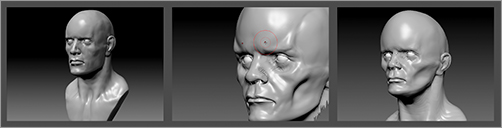
2. Using the Move brush, shift the shape of the head around to give it a more sickly character. I begin by reducing the mass beneath the cheekbones to give the face a more gaunt appearance (Figure 6-1).
3. Using the Clay Tubes brush, build up the skeletal structure of the zygomatic bones (commonly called the cheekbones) as well as the temporal ridge of the skull and the frontal eminence. This helps accentuate the skeletal landmarks beneath the skin, adding a sense of anatomical realism as well as a malnourished, creepy quality to the face.
Figure 6-1: A generic human head ZTool. Using the Move brush, change the shape of the generic head, accentuating the bony landmarks of the skull.
4. Returning to the Move brush, enlarge the cranium as well as the eyes to suggest a more fetal proportion to the head (Figure 6-2). Perhaps this character was never a normal human but a genetic experiment grown for this very purpose. As a result, the skeletal development would be skewed. The slightly disturbed head proportion will also have a more unsettling effect on the viewer. By understanding head and facial proportions, you are able to make informed decisions like this in how to break the rules for your own needs. We will also be carving out the back of the head and filling the skull with mechanical tubes and pistons, so the extra space will be useful. To the viewer, a slightly oversized infantile head connected to a massive robotic body implies a strength that is not tempered by rational thought.
Figure 6-2: Create a more infantile proportion to the head.
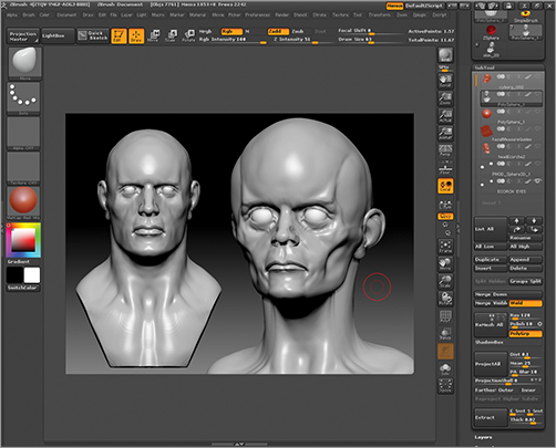
At this stage, I want to isolate the face and cranium as well as carve away a negative space in the back of the skull. To do this, we will use the Clip brushes to slice sway the neck geometry. The Clip brushes are available under the ZBrush Brush menu. There are a few variants, but here we are using the ClipCurve brush. Later in this lesson we will use the ClipCircle brush briefly to detail some mechanical elements.
1. Step down to a lower subdivision level and, using the Move brush, compress the unneeded shoulder geometry up into the neck. Smooth and shift the faces to gather them beneath the head, where they can easily be clipped (Figure 6-3).
Figure 6-3: With the Move brush, compress the neck and shoulder geometry beneath the head, where it can easily be clipped.

2. Press the B key to open the Brush menu and then the C key to show the brushes that start with the letter C. Select the ClipCurve brush from the menu and rotate to view the head from the side.
3. Ctrl + Shift + Click drag to create a clipping line. When drawing a clipping line, any geometry that falls on the shaded side of the line will be clipped while the unshaded side will remain untouched. Figure 6-4 shows the process of slicing the neck away. Remember to press Alt once to create a curve and twice to create a hard angle.
Figure 6-4: Use the Clip brushes to slice the neck geometry

The ClipCurve brushes work by pressing Ctrl + Shift + Click and dragging a line. The shaded side of the line will be “clipped” from the geometry on the unshaded side of the line, which will remain unchanged. When you are drawing a clipping line, press spacebar to reposition the line, press Alt once to insert a curve anchor point in your line, and press Alt twice to insert a hard angle anchor point.
4. At this point, we will carve away some negative space at the back of the skull (Figure 6-5). This will help interrupt the viewer’s expectation that the cranium will be a solid mass and allow us to play with adding some interesting mechanical shapes inside to suggest some complex life support system. We will use the ClipCurve again for this cut.
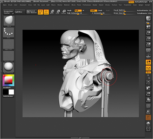
5. As a final touch, we will add come cylindrical details using the ClipCircle brush. From the Brush menu, select the ClipCircle brush. This brush differs from the ClipCurve brush in that it draws a circular clipping area. Notice there is a crosshair in the center of this circle. We will now use the ClipCircle brush to add some points on the head where tubes will later insert (Figure 6-6). The ClipCircle brush has two interesting effects. If the circle is drawn so the center crosshair is outside the geometry, it will carve away a circular shape. If the crosshair is inside the geometry, it will create a countersunk cylinder shape. Draw the ClipCircle and make sure the center point is within the geometry to create the tube connectors as shown (Figure 6-7).
Figure 6-5: Carve away the back of head.

Figure 6-6: The ClipCircle in use
Figure 6-7: Pipe attachment points made with clip circle
Avoiding Undercuts
Something to be careful of when working with the Clip brushes is undercuts. The Clip brush is actually a flattening effect, so you want to avoid any geometry that extends out beyond the volume of the head. The feathered edge of the curve does not actually cut, but rather it flattens the existing geometry into a place that corresponds to the curve. The graphic below shows how this can create thin wings of edges if you slice an area that is curving back and away.
Creating the Body
We will now create the torso mass for the cyborg character. We will do this by sculpting a basic Polysphere primitive. The Polysphere is a very versatile shape that can be manipulated into all manner of forms using the standard ZBrush sculpting tools. In my book ZBrush Character Creation, I illustrated how to create a complex creature bust using just such a polygon sphere. In this case, we will create the torso structure of our character from the sphere using a combination of the Move brush, Trim brushes, and Clip brushes. We will then use a combination of ZBrush hardsurface tools such as the Polish and Clip brushes to further refine the shape.
Creating the Torso
Here we will look at the steps to create the torso. This will be created by using the Polysphere ZBrush model to create a basic ribcage form. From this base shape, we will build the rest of the mechanical elements of the body.
1. Open the Lightbox browser and under the ZTool menu select the Polysphere tool. This is an all quad sphere form with no poles. These are ideal balls of digital clay for all manner of forms and I use them often. Once the Polysphere is selected and loaded into ZBrush, return to the head ZTool and append the Polysphere as a SubTool using Tool SubTool Append.
2. This Polysphere will be the basis of the torso. Use the Move brush to shape it into the egg form of a ribcage (Figure 6-8).
Figure 6-8: Shape the sphere into an egg form to create the ribcage.

The Mechanical Details of the Neck
With the basic torso created, we will now look at how to create some detailed mechanical details for the cyborg. We will begin by creating some mechanism to move the head and neck. These pieces will be based on the natural shape of the anatomy of this area. To create these pieces, we will use ZBrush primitives as well as some new mesh generation tools that have been added to ZBrush 4. One of the methods we will use is called Shadowbox. Shadowbox is a unique new mesh generation technique that allows you to create new geometry by drawing it in front, side, and top views. This is an incredibly fast way to create complex forms for further sculpting. We will also use ZSpheres to quickly generate section of mesh to sculpt into a spinal cord. This section is intended to illustrate how complex new pieces of geometry can be created on the fly.
Greebles
Greebles may be an unfamiliar term to many of you. It dates back to the days of physical model making for film when many miniatures were built from both custom parts and pieces of old model kits, toys, scrap, and whatever else might be handy. Greebles were small mechanical details that served no real purpose other than to break up a surface and make it appear to be mechanically functional. Greebles are an important part of design. While it is often important to understand the form and function of each piece you design, there are times when “greeble” detail is appropriate. In this section, we will create the neck anatomy of the cyborg. This will include both visually functional parts that mirror human anatomy as well as smaller greeble details to add visual interest to the area with texture and shape contrasts.
The Mechanical Shoulder Apparatus
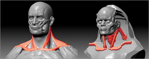
We will begin by creating some mechanisms to move the head. I want to base these parts on the actual sternomastoid muscles of the human neck (Figure 6-9). I believe the anatomy of the neck is imprinted on the mind of the average viewer because they see human heads and necks every day. It’s something that we understand even if not on a technical level. Most people have a sense of the two large muscles of their neck. Creating mechanical parts that mirror the form and function of human anatomy will help the viewer understand the function of the parts when they see them. It also helps keep a humanoid look to the head and neck while using non-human elements. The viewer should assume the structure would work because it subconsciously implies the anatomy of the neck visible on most people. This will help create both visual interest and character.
Figure 6-9: The finished neck structure should mirror human anatomy.
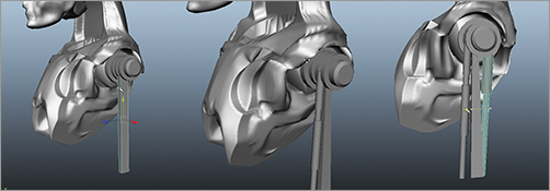
1. From the Tool menu, select a cylinder 3-D tool. Under the Tool Initialize menu, set X and Y size to 20. Click Make PolyMesh3D to convert this primitive to an editable 3-D mesh (Figure 6-10).
2. Append this into the cyborg tool. We will now create some greeble detail on the ends of the pistons. Greebles is a term from physical model making. It means any mechanical detail shape that serves no purpose other than to increase the visual interest and complexity of the surface. From the Brush menu, select the Mask Rectangle brush and mask some strips along the ends of the cylinder. Invert the mask, then use Tool Deformation Inflate to offset these details (Figure 6-11).
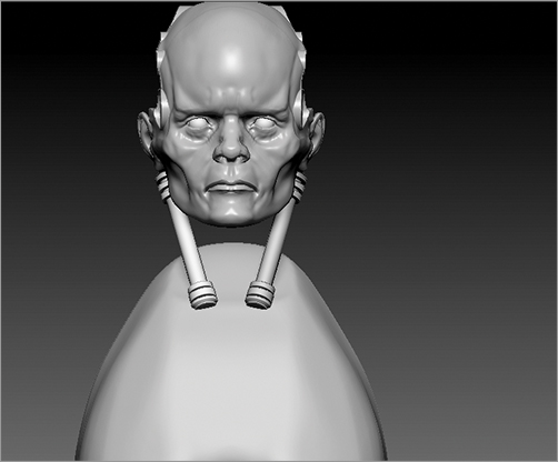
3. Use the Transpose tools to move the piston into place and mirror it across with the SubTool master ZScript (Figure 6-12).
Figure 6-10: Making the cylinder primitive

Figure 6-11: Detailing the piston with ridge details from a combination of masking and the inflate slider
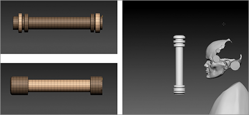
Figure 6-12: Mirrored pistons—notice the geometry has been duplicated and positioned behind the head as well to add complexity
We will now create the clavicles (or collarbones) for the character using Shadowbox. Shadowbox is a tool that allows you to create complex shapes by simply drawing them in front, side, and top views using the masking brushes. It’s an incredibly fast technique for making editable meshes of complex forms that would be far more difficult to model under other circumstances. If you can sketch it, you can create 3-D geometry of it in Shadowbox. ZBrush has several Shadowbox tools available in the Lightbox ZTool menu (Figure 6-13).
Figure 6-13: Shadowboxes are loaded via the Lightbox.
1. Open Lightbox and select Shadowbox 64. There are two Shadowbox tools here and each one will generate geometry in the resolution notes in the filename—Shadowbox 64 being the lowest res and Shadowbox 128 the highest. Since we will want to divide and detail the geometry more before the model is complete, we will use the lowest res Shadowbox since we can then just add geometry as we need it.
2. The Shadowbox will now be the active tool in ZBrush. Return to the cyborg ZTool and append the Shadowbox as a SubTool under the Tool SubTool menu. Append this Shadowbox into your Cyborg as a SubTool and use the Transpose tools to place it in the vicinity of the clavicle or collarbone (Figure 6-14).
Figure 6-14: The Shadowbox placed in the area where we will build the collarbone

3. From the Brush menu, select the Mask Pen brush and draw the shape of the clavicle from above. This will instantly create the shape you draw. You can further refine the form by rotating to the front and drawing the shape in the front profile. When you are satisfied with the shape, exit Shadowbox by pressing Tool SubTool Shadowbox. This will place the new geometry in our SubTool menu (Figure 6-15). The clavicle can be further shaped and refined with the ZBrush sculpting tools, as it is now a polymesh, which is fully sculptable.
Figure 6-15: Shadowbox in use to make clavicles
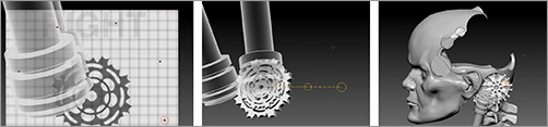
Further details are created in the neck area with Shadowbox as well as by duplicating and repositioning repeating elements. Figure 6-16, for example, shows a gear structure created entirely with Shadowbox. See the video on the DVD or download files for this process in full. A complex character like this can be built by duplicating and layering a selection of relatively simple base parts.
Figure 6-16: This complex gear structure was created with Shadowbox and is viewable on the DVD or download files.
Shaping the Torso
We have now established the basic torso structure, including the mechanical details of the neck and shoulders. Next, it’s time to add shape.
1. First, move to the side vide and pull the shoulder area up so it sits behind the head like a carapace (Figure 6-17).
2. Use the ClipCurve brush to shape the front and back of the carapace as seen in Figure 6-18.
3. Make sure to place the torso back from the head, leaving a good space between the two forms. Note the negative space from the side view between the head and shoulder/carapace structure (Figure 6-19). This area will be filled with mechanical parts later to add interest to the space and give the impression of mechanization. By allowing the negative spaces to remain here, it reinforces the fact that this is a head attached to a machine and not a man in a suit.
Figure 6-17: Pull the back of the ribcage up into a carapace behind the head.

Figure 6-18: Shaping the carapace with the ClipCurve brushes

Figure 6-19: Negative space between the head and shoulders from side view
Man in a Suit
In creature design, it is often important to avoid the man-in-a-suit look. Decades of monster movies have created an audience familiarity with the look of a performer inside a rubber suit. There are proportional points that cannot be easily changed, just like the proportions of the face are locked in even for prosthetic makeup unless some digital alteration can take place. Many directors will stress they want a creature design which obviously cannot be accomplished with a suit since it will best exploit the power of CGI and create a creature the audience has most likely not encountered before. Some effective designs from the past include Geiger’s Alien, Pumpkinhead, and more recently Wink from Hellboy 2, the Pale Man and the Faun from Pan’s Labyrinth as well as many of the robots from the film A.I. Part of the reason these are so successful is because the artists, designer, and director are experienced creature designers and know what visual cues create the man-in-a-suit look. Through clever design, these conventions were broken and exploited to make memorable characters. They understand what the audience expects and then try to confound those expectations.
Refine the Torso Details
When creating the mechanical details of the torso, we will take advantage of the Trim Dynamic brush, the Planar brush, and the Polish brush. Some basic planes are created using the Trim Dynamic brush. The Trim Dynamic brush allows you to polish and flatten the surface along a curved path. This helps create machined surfaces like car bodies and other semi-organic machined surfaces. Use this brush to polish the curves of the torso. The Planar brush will trim to a specific depth along the surface normal. This depth is set under the Brush menu by controlling the depth mask imbed slider. Any areas that appear noisy or lumpy can be easily flattened by using the MPolish brush. The MPolish brush will polish out imperfections in the surface leaving a smooth refined surface.
1. At this stage, the torso shape is roughed in, but it appears soft and unrefined. There is very little machined or mechanical about it. We will use the Planar Cut brush to slice in the small flat planes on the torso sculpt (Figure 6-20). The Planar Cut brush depends on the Depth mask to control how deep into the surface it slices. The Depth control is found under the Brush Depth menu. The circle represents the brush’s area of effect and the dot at the center represents the depth into the surface it will cut (Figure 6-21). Lower this dot slightly beneath the surface of the sculpt and when you use the planar cut brush it will cut into the sculpture to the depth measure you specify here. This process can be seen on the associated video.
Figure 6-20: The planes shown here are created with the Planar Cut brush.
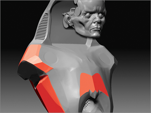
2. In addition to the flat planes on the torso, there are dynamic curves that, while appearing flat and machined, follow a contour much like the machines lines in a car body for example. Figure 6-22 shows these areas. These are created using the Trim Dynamic brush. Trim Dynamic will flatten the area beneath the brush by dynamically sampling the brush position and surface normal beneath the center of influence. This allows you to create curved machined contours.
3. Build up areas slightly with the Clay Tubes brush, then knock back the plane using the Trim Dynamic brush as seen in Figure 6-23
Figure 6-21: The brush depth control menu
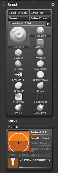
Figure 6-22: The Trim Dynamic planes
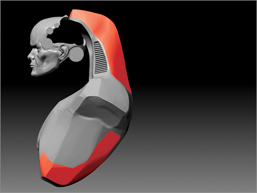
Figure 6-23: Using the Trim Dynamic brush
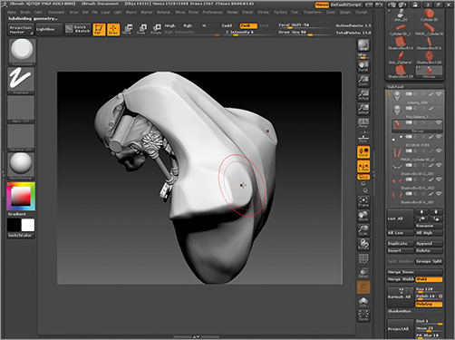
4. The intake vent on the side of the shoulder structure is created with a simple mask. Use the Masking brush to isolate the area for the vent (Figure 6-24), invert the mask, and from the alpha menu select alpha 28. Adjust the V Tiles slider to 32 to create the vent alpha. Using a dragRect stroke, draw the vent alpha over the unmasked area (Figure 6-25).
That completes the torso section. Figure 6-26 shows the stages from start to finish. You may also refer to Figure 6-27 for a summary of each part of the torso and how it was created. We will now move into some more detailed mechanical structures of the anatomy of the character.
Figure 6-24: Isolate an area for the vent structure.
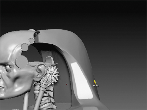
Figure 6-25: Modify the alpha and draw the vent.
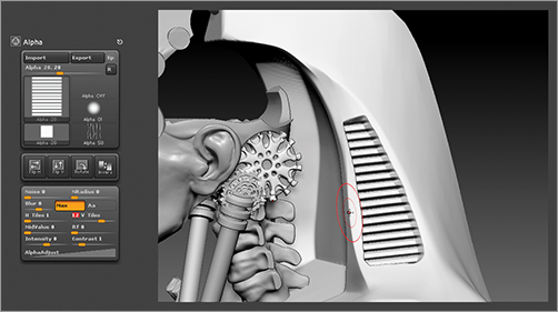
Figure 6-26: From start to finish, this image shows the progression of the torso planes.
Figure 6-27: The mechanical details summarized

Create a Spinal Cord and Pipes
Here we will add a length of spinal cord to give some more organic elements to the neck. We will also create some pipes that suggest coolant, oxygen, or other important materials being circulated around the cyborg’s body. These kinds of details really add visual interest and can also be design elements in themselves, especially when creating the gesture and sweep of the pipes. Parts like these can help guide the eye through the design if you treat them as more than items just “stuck on” the final form. The spine is created by using ZSpheres while the pipes will be created using ZSketch. Be sure to check the video for an in-depth look at the process of making these parts.
1. Append a ZSphere into the SubTool stack and position it in the neck area (Figure 6-28). Draw a ZSphere chain to create the cervical (neck) spine.
2. Rotate to a back view and draw a series of child ZSpheres off the side to represent the transverse processes of the spinal cord (Figure 6-29). The transverse process is the protrusion on each side of the vertebrae (Figure 6-30).
3. Draw child spheres off each link in the center of the chain that extends toward the back (Figure 6-31). These will be the spinous processes, or the bony protrusions that come off the back of the spine.
4. Convert the ZSphere chain into a polymesh using the Make Adaptive Skin button under the Tool Adaptive Skin menu and append it into your SubTool stack. You may choose to delete the ZSphere chain now or hide it by turning off the eyeball icon in the SubTool menu. Use your favorite brushes to sculpt the spinal section. I used Standard, Move, and Inflate. Remember to take advantage of the polygroups created by the ZSpheres to easily mask parts close together and create tight spaces where the vertebrae come into contact with each other (Figure 6-32). As a final touch, I use the ClipCurve brush to slice an arc down the length of the transverse processes of the spinal cord. Figure 6-33 shows the spinal cord in position.
Figure 6-28: Append a ZSphere into the neck area and draw a short chain the length of the spinal section you want.

Figure 6-29: Draw a series of child ZSpheres off the side to represent the transverse processes of the spinal cord.
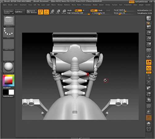
Figure 6-30: The components of the spine labeled
Figure 6-31: The spinous processes

Figure 6-32: Making the spine

Figure 6-33: The final spine

We will now create a system of pipes that connect the cranium to the carapace of the body suit. This will break up the negative space between the head and the body as well as create the impression of body fluids, fuels, and other supply conduits connecting the body to the head.
The piping is created with ZSketch. ZSketch is a stroke-based modeling tool that allows you to build up geometry by creating strokes with a Sculpting Brush. These strokes are well suited to creating vines and tubes quickly and easily.
1. Append a ZSphere into the Cyborg tool and Transpose Move it to the center of the head.
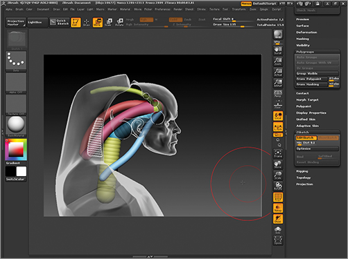
2. Enable ZSketch under Tool ZSketch Edit Sketch (Figure 6-34). You will automatically be ready to start drawing strokes with the ZSketch brushes. Create the tubes as seen in Figure 6-35.
Figure 6-34: The Edit Sketch button
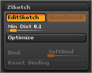
Figure 6-35: Pipes created in ZSketch
3. When you are ready to convert them to geometry, set the Tool Unified Skin value to 512 and press Make Unified Skin. Append this new skin into the cyborg ZTool. You may now delete the ZSketch SubTool, leaving the Unified Skin. The ribbed pipe texture is created with the Stitch brush. Replace the alpha with Alpha 59 rotated once with the Alpha Rotate button. This will create a repeating rib texture along the length of the brush stroke (Figure 6-36). Simply drag it down the length of the tube to create the conduit-style surface.
Figure 6-36: Using the modified Stitch brush to create a ribbed texture on the conduit pipes
Create the Arms and Chest Muscles
In this section, we will look at ways to add new geometry to the cyborg model with third party modeling tools. We will use the new ZBrush plug-in GoZ, which allows a seamless integration of outside 3-D modeling software with ZBrush. GoZ supports Maya, 3D Studio Max, Modo, Cinema 4d, and others, but we will be specifically using it with Maya. The plug-in allows us to export our ZTool to Maya, where new geometry can be added and then brought back into ZBrush seamlessly. This adds a new level of flexibility to the ZBrush workflow, which leverages the strengths of the Maya modeling toolset with ZBrush.
GoZ is a tool to link ZBrush with any number of third party modeling and animation packages. We will use it to transfer models to and from Maya. When you press the GoZ button, ZBrush exports your current SubTools to a Maya scene file. Once in Maya, you can make changes to the topology or even add new objects and return them to ZBrush. We will use GoZ to add basic arm structures using Maya primitives.
1. Turn on visibility on the torso and head. Make sure all the other SubTools are hidden. Press the Visible button under the File menu (Figure 6-37). This will export just those visible SubTools to Maya using GoZ. Maya will automatically open with the SubTools visible in the scene file.
Figure 6-37: Press the Visible button to export the visible SubTools to GoZ.

2. The visible SubTools will export to your GoZ-enabled application. In this instance I use Maya as my GoZ app. Figure 6-38 shows the torso and head base subdivision levels exported to Maya. I can now build new geometry in scale and relationship to these parts and transfer them back to ZBrush.
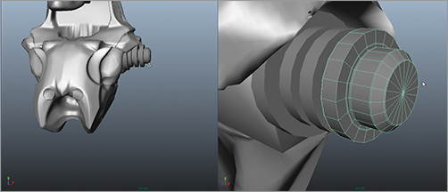
3. The shoulder mechanism is built by scaling and duplicating a series of cylinders at the socket for the arm. These should appear to be rotational elements for the arm (Figure 6-39).
Figure 6-38: The base subdivision level for the head and torso exported to Maya with GoZ

Figure 6-39: The arm is started by duplicating and scaling a series of cylinders at the shoulder.
4. The arm is constructed from basic box and cylinder primitives, as seen in Figure 6-40. A polygon box is created and positioned to serve as the basis for the humerus bone. Since I know these arms will be covered in organic tissue, I’m not too concerned with details outside the joint and articulation areas.
Figure 6-40: Continuing to develop the arm by adding primitive boxes and cylinders
5. When the structure is complete, select all the parts with a marquee and group them together with the Ctrl + G hot key. Duplicate them across the X axis by going to Edit Duplicate Special ![]() . Reset the settings and then set scale X to –1 to flip the copy across the X axis. Click OK (Figure 6-41). This is basic polygon modeling and is documented fully on the video on the DVD or download files.
. Reset the settings and then set scale X to –1 to flip the copy across the X axis. Click OK (Figure 6-41). This is basic polygon modeling and is documented fully on the video on the DVD or download files.
When you are done modeling, select all the parts. From the shelf marked GoZ, press the GoZ button to transfer the new parts back to ZBrush (Figure 6-42). Back in ZBrush, append the new arm geometry into the cyborg ZTool (Figure 6-43).
Figure 6-41: Arms duplicated across the X axis

Figure 6-42: Press the GoZ shelf button when the parts are selected to transfer them back to ZBrush.
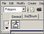
Figure 6-43: The new arm geometry transferred into ZBrush
Adding Muscle Tissue
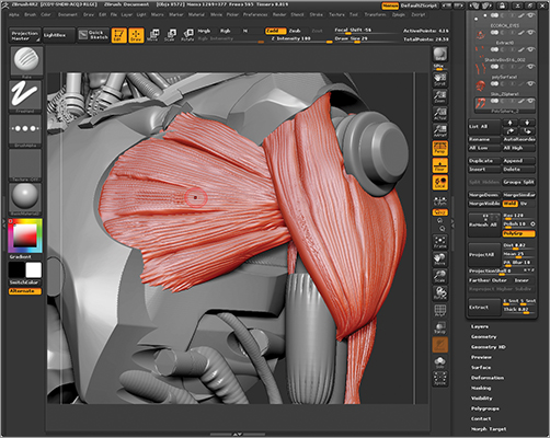
At this stage, I want to add some muscle tissue to the rest of the body that is intertwined with the mechanical parts. As it stands, the head is the only organic element in the biomechanical character. Using a Polysphere, we will sculpt the pectoral muscles connecting the mechanical arms to the chest chassis (Figure 6-44).
Figure 6-44: This illustrates the human anatomy we are trying to suggest with these biomechanical structures.
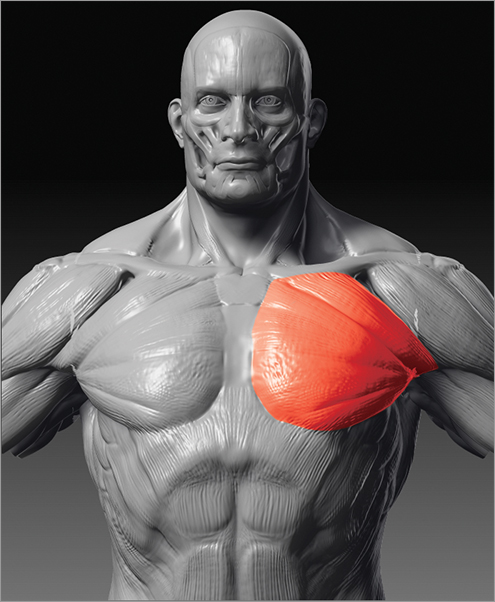
1. Append a Polysphere into the ZTool and using the Move brush, shape it into a form consistent with the pectoralis muscle. Notice how the muscle is shaped like a large fan extending from the arm bone. I try and mimic the forms of the natural body as much as possible when building these biomechanical elements (Figure 6-45).
2. I repeat this process to add deltoid muscles (Figure 6-46), making sure they weave over the pectoralis and around the mechanical articulation of the shoulder (Figure 6-47).
3. The muscles of the bicep and forearm are created with ZSketch. First append a ZSphere into the tool and draw a chain down the length of the forearm (Figure 6-48).
Figure 6-45: Create the chest muscles.
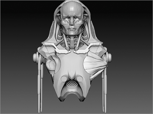
Figure 6-46: Create the deltoid muscle.

Figure 6-47: Interweaving of muscles
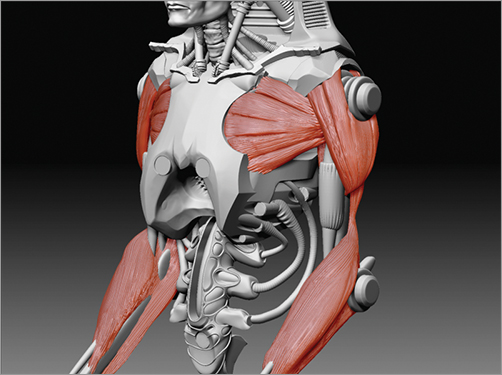
Figure 6-48: Draw a ZSphere chain down the forearm to facilitate the ZSketch strokes for the flexor and extensor muscles.

4. Enable edit sketch under Tool ZSketch and draw strokes down the forearm to build up the shapes of the muscle forms (Figure 6-49). I leave the bicep muscle out because its function is almost identical to a piston pulling on the lower arm. In its place I leave the pneumatic piston geometry visible.
5. To add the striations of the muscle tissue, add a few subdivisions to the mesh. Select the Rake brush and turn on lazymouse by pressing the l hot key. This will help you make long, even strokes along the muscle surface (Figure 6-50).
Figure 6-49: Use ZSketch strokes to build up the volume of the forearm muscles.
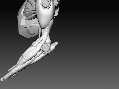
Figure 6-50: Adding muscle striations
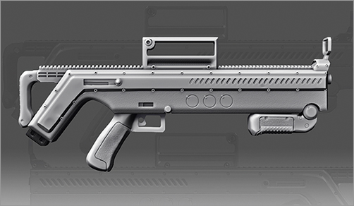
Character Accessories in ZBrush
Since ZBrush’s hardsurface modeling tools are so useful for creating character accessories, I have also included a video on making a sci-fi gun using ZBrush. Please look on the DVD or download files for this bonus content. (The gun seen here was designed by Christian Pierce.)
Create the Lower Body
The lower body spinal section and pipes are created using a combination of tools. The pipes are generated with ZSketch, using the same technique as before. The lumbar (lower) spinal section is created using ZSketch and the Group Loops function to create the more intricate details. Follow these steps to create the lower body section. Be sure to check the DVD or download files for a video that details how to use ZSketch in conjunction with Group Loops to create unique forms like this.
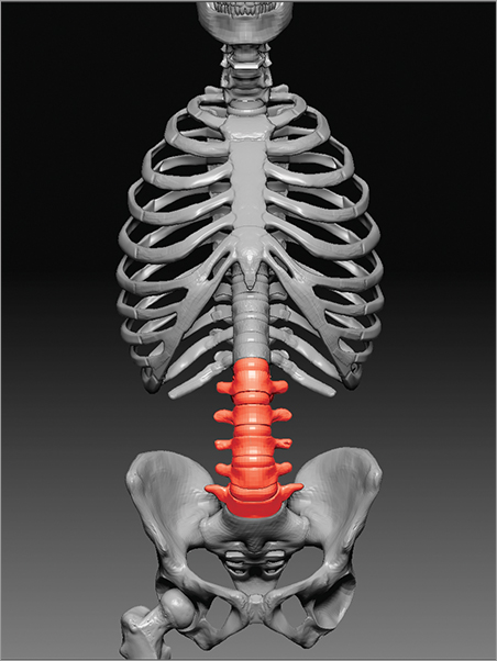
1. Append a ZSphere into the SubTool stack. Draw a chain that extends from the torso down toward the hip area. Make sure it is long enough to feel like a functional waist and spine for the character. You will want to use this form to balance the upper body. Draw a few branches off the central ZSphere chain as seen in Figure 6-51. This structure is designed to mirror the configuration of the lumbar vertebrae, only larger and mechanical in nature (Figure 6-52).
Figure 6-51: The ZSphere chain for the lumbar section

Figure 6-52: The lumbar spine of the skeleton
2. Enable edit sketch under Tool ZSketch. Using the Sketch 1 and Sketch A brushes, build up the form into an interesting shape. Try to consider how the mechanical structure will look when it is complete. Each ZSketch stroke will be a polygroup and later in this section we will isolate and extrude each stroke. Keep this in mind as you draw the stokes (Figure 6-53). There are other stroke brushes available in the Lightbox under the Brush ZSketch menu. I encourage you to experiment with the Sketch 2 and Sketch 3 brushes as well as Sketch B and Sketch C. These brushes build up form in different degrees of intensity.
Figure 6-53: Strokes are polygrouped by default.

3. When you have completed building up the general form of the lower body, create a Unified Skin by pressing Tool Unified Skin Make Unified Skin (Figure 6-54). This will create a new skin tool in the tool palette that represents an editable mesh of your ZSketch.
Figure 6-54: Create an editable object from the ZSketch with the Make Unified Skin button.

4. Append the Unified Skin into the SubTool stack. You will now delete the ZSketch now or hide it from view.
5. At this stage, we will use a tool called Group Loops to isolate each polygrouped stroke with an edgeloop (Figure 6-55). This will allow us to create some interesting and intricate surface details with sharp machined edges. Group Loop the mesh by pressing the Tool Geometry GroupLoop button. Notice how this slightly smoothes the mesh and adds a defining edgeloop around each polygroup.
6. Isolate the main loop seen in yellow here by Ctrl + Shift + Clicking on the polygroup. This will isolate the polygroup and allow you to mask it independently of the rest of the model. Ctrl + Click on the background to mask all. Ctrl + Shift + Click on the background to reveal the full mesh again and invert the mask by Ctrl + Clicking on the background.
Figure 6-55: The lower body with Groups Loops applied. The main edgeloop is isolated. The model is masked, with the main loop unmasked.

7. You may now extrude just the edgeloop by opening Tool Deformation and dragging the inflate slider. This will offset the unmasked areas from the rest of the model creating a very interesting surface detail. You may further offset groups by selectively masking and using the inflate slider or the move tools (Figure 6-56).
Figure 6-56: Use the inflate slider to alter the unmasked edgeloop and add an interesting surface detail. This is the result of inflating the edgeloop to offset it from the rest of the surface

8. The pipes are created with ZSketch. I appended a single ZSphere into the torso and then drew the strokes from the torso to the contact points on the spine. Use the Move brush to shift the pipes around and make it flow in the direction you wish. Create a Unified Skin and then mirror the structure across the X axis using the SubTool Master Mirror function (Figure 6-57). Check the DVD or download files for a video of this process in action.
Figure 6-57: Adding the pipes to the lower body using ZSketch and then converting to a skin and mirroring the resulting geometry

This completes the modeling and design of this figure. In this chapter we have seen how to use ZBrush’s hard surface modeling tools to sketch mechanical forms much in the same way organics are created easily in ZBrush. These tools free the designer to think in different kinds of shapes with the same loose and freeform approach. Usually mechanical designs must be planned painstakingly before being approached in 3-D. Using these techniques, a much more “sketch” oriented approach is possible. Please be sure to see the DVD or download files for a video of this design process.
The final image is created by compositing images from the BPR render passes. Noise textures were laid in as overlay layers to add a sense of grime to the image (Figure 6-58).
Figure 6-58: The final image