Chapter 11
ZBrush for Digital 3-D Printing
As we have seen in the previous chapters, ZBrush can be used for all manner of concept design and illustration purposes. One technological innovation that makes ZBrush even more powerful is the ability to create physical 3-D prints from digital geometry. This can be accomplished by various kinds of machines. The two most common are 3-D printers and 3-D mills. 3-D printers are the most common for creating small- to medium-scale figures and parts from 3-D data. 3-D mills are used for making larger-scale objects. In this chapter, we will focus on 3-D printing, as it is the most pertinent to the process of creating design maquettes from 3-D objects. The quality and level of detail in 3-D printing is far higher than what is achieved with 3-D milling technology.
The ability to print a physical object from a 3-D model gives designers an incredibly powerful tool, as digital designs on the computer can now be turned into physical objects in a matter of hours. What was once locked on-screen and only visible in the computer can now be placed in a client’s hand. A director can see, light, and interact with a character design in a manner that was previously only possible through the use of traditional-sculptor and model-making techniques. This physical maquette can be used throughout the pipeline, helping various departments that need a reference figure of a character.
Beyond the application of just concept-design maquettes, 3-D printing has allowed ZBrush to become a standard tool in the toy and collectible industry. Gentle Giant Studios, a leader in collectible and toy production, uses ZBrush heavily in their pipeline. I established the ZBrush presence at Gentle Giant in 2005 and we did some of the first work in crating collectible figures entirely using ZBrush. In a few short years, ZBrush sculpting had become the best solution to most projects in the workshop, as opposed to more traditional wax-and-clay approaches. In this chapter, I hope to share some of the workflow I used to create a physical model from digital data.
The Brief: A Finished Physical Maquette
The brief for this chapter is to create a fully realized physical maquette based on the Interdimensional Traveler design. The 2-D illustration has been approved and now the director wants to see what this character might look like fully finished. To accomplish this, we need to revisit the original model and resolve any unfinished areas to a high level of detail.
In this chapter, we will look at the various methods of creating 3-D objects from digital data. This will include 3-D printing as well as milling. We will focus on 3-D printing technology as it offers much higher detail and is a more common solution for creating small- to midsized-physical objects in high detail. We will examine the various applications of 3-D printing from film and games to collectibles and even fine art. Finally we will look at the process I took to create the final 3-D print of the Interdimensional Traveler maquette.
Often you will hear the term rapid prototyping used as a catchall to refer to the process of creating physical objects, or prototypes, from 3-D digital data. The two most common kinds of technology used at this time to generate physical objects from a 3-D model are 3-D printing (stereolithography) and 3-D milling (CNC milling). 3-D printing involves the extrusion of micron-thin layers of plastic to build up an object layer-by-layer inside a 3-D printer. Milling is performed by a robotic arm with a cutting head that effectively carves away a shape based on 3-D data.
3-D printing allows for far more delicate pieces and retains fine details. The drawback can be that the size is limited to the size of the printer bed. Milling, on the other hand, works very well for large objects. Because the machine head tends to carve out of foam, your detail can be limited to the size of the smallest mill head. This can work just fine, especially for very large figures where details would actually be much larger than they would be on a smaller maquette. Often a 3-D mill is further finished with real-world sculpting before being molded and cast. A 3-D print may be reworked but often with the newer high-quality machines, the piece off the printer is ready for molding after a light cleaning.
3-D Printers
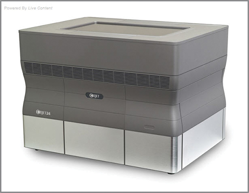
There are a few different manufacturers who produce 3-D printers. The two most common machines I have encountered are 3-D systems Thermojet and the Objet “Eden.” I have worked with both and I find the Objet printer to be stunning in its detail and quality of print. Figure 11-1 shows the Objet Eden printer.
Figure 11-1: Objet Eden printer
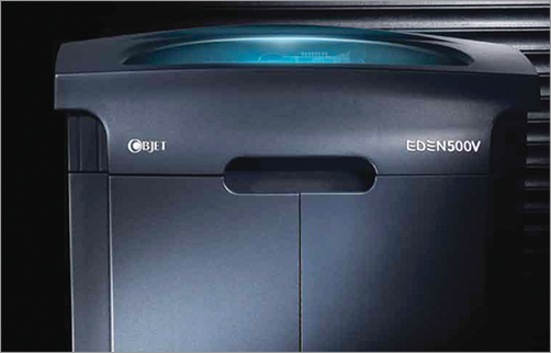
These printers work by a process called stereolithography. This process involves the extruding of a thin layer of plastic called acrylic-based photopolymer, which is catalyzed by a UV light. Each layer is so thin it must be measured in microns (or micrometers) rather than millimeters. The Eden machines from Objet lay down layers of plastic that are merely 16 µm thick (the symbol µm means microns, or micrometers—i.e., a millionth of a meter; you will encounter this in the documentation for these kinds of machines). As each layer is extruded and cured, a new layer emerges, effectively growing the part from the printer bed (Figure 11-2). The space around the plastic is filled with support material, a waxy substance that washes off later. Because each layer is merely microns thick, a high degree of detail can be reproduced. When a model is properly decimated and oriented on the printer bed, details as small as skin pores are easily reproduced. Decimation is the process of lowering the overall polygon count while retaining all the model details. Decimation is integral to the 3-D printing workflow, and we will look at it in-depth later in this chapter.
Figure 11-2: This image illustrates the process by which a part is “grown” in a 3-D printer tray.
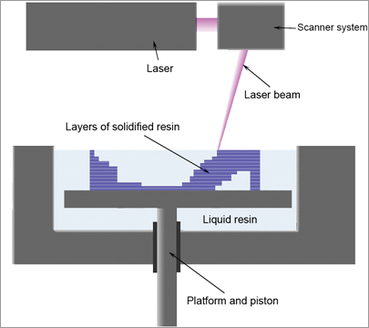
©Materialgeeza
On the modern generation of high-end 3-D printers, I have seen models printed with this machine that needed little to no cleanup before being molded for production. Often the single generation loss of detail introduced by the molding process was enough to reduce the remaining surface lines from the build. Figure 11-3 shows a mesh detail from a superhero costume 3-D printed by Gentle Giant Studios. The level of detail here is phenomenal and the build lines are essentially invisible! Build lines are created by the various layers of extrusion material, show up as fine lines on the print, and need to be removed by a light cleanup.
Some printers use a different material than the resin used by the Objet printers. The ZCorp printer line uses a material mix that can also support the printing of some color from the model (Figure 11-4). Figure 11-5 shows a design by Nick Benson printed on the ZCorp Spectrum 510.
Figure 11-3: Costume detail from an Objet Eden print at 12 inches tall

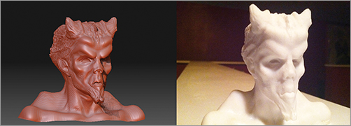
Figure 11-5: This demon bust was printed by artist Nick Benson on a ZCorp 510 3-D printer.
3-D Milling
3-D mills or CNC milling machines are generally used for larger objects than are possible to print on a 3-D printer. They are somewhat faster and yet reproduce less detail by virtue of the material employed and the fact that a carving approach is used rather than an additive building process. The mill can operate in multiple axes, allowing a movable robotic head to carve away the shape of 3-D data in a block of material (Figure 11-6). 3-D milling is generally used for large-scale objects and the detail is generally limited by the side of the milling head and the quality of base material being milled. We do not focus much on milling in this chapter because you will almost always be printing with a stereolithography machine or a 3-D printer to get the level of detail you will want in your figures.
One drawback to 3-D milling is its inability to reproduce undercuts. Undercuts are areas of a shape that dip back and underneath, like the nostrils or insides of ears (Figure 11-7). Because a mill carves the shapes out, you cannot mill an undercut as easily as you can print an object with an undercut. Figure 11-8 shows a life-sized King Kong milled by Gentle Giant for the premiere of King Kong in New York City. The data used was the actual Kong model, reworked and detailed in ZBrush. This amazing project was overseen by Gino Acevedo of Weta Workshop for Gentle Giant Studios.
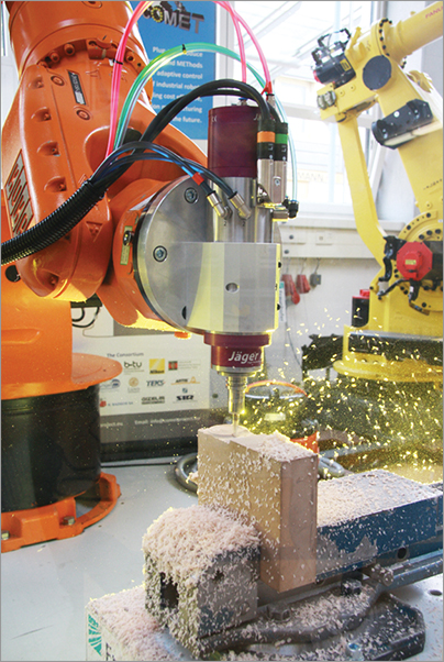
Figure 11-7: Undercuts are areas that cannot be accessed by the milling tool—they are areas that curve back and away from the direction of the milling head.

Figure 11-8: This life-sized King Kong was milled on a CNC machine from original data of the Kong model.
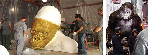
Image courtesy of Gentle Giant Studios.
In this section, we will look at the various applications of 3-D printing in the entertainment, art, and manufacturing industries. When I refer to 3-D printing, I am talking about stereolithography as opposed to 3-D milling. The combination of ZBrush and 3-D print technology has opened huge new vistas to artists working in this medium. Not only can we use ZBrush to print maquettes as a powerful concept-design tool, but the same technology extends into prop manufacture and even fine art and collectible production based on your digital sculpture.
3-D Printing for Digital Maquettes
Here we can see some examples of how a concept design can be taken into the physical realm by printing a 3-D model from the ZBrush data (Figure 11-9). Many times directors will respond better to seeing and holding a representation of the character in their hands. Filmmakers are highly visual people so they will often like to be able to see a character under real lighting conditions even if it is in miniature.
Figure 11-9: This figure shows a sculpture of Senator Tumblestone, made and printed by Jelmer Boskma.

Image from www.jelmerboskma.com
Being able to produce concept maquettes like this has been hugely beneficial beyond just getting design approvals. Once a maquette is approved, it allows other departments to have the figure for reference. The 3-D print can even be painted to illustrate possible skin texture variations.
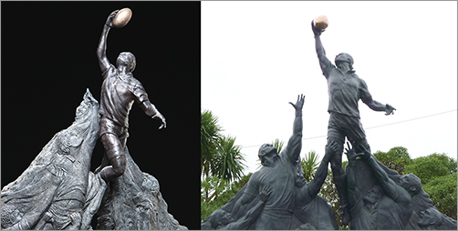
Concept design is not limited to just the entertainment industry. Figure 11-10 shows a maquette for a monumental piece of public sculpture here in Wellington, New Zealand. The central figure was conceptualized in ZBrush and then milled in foam as basis for the final sculpture. You can see how ZBrush and digital printing is now making headway into the world of fine art, allowing sculptors to develop ideas much quicker and bringing them to life with greater ease.
Figure 11-10: RWC sculpt maquette and on site
3-D Printing for Toys and Collectibles
In addition to concept maquettes, the 3-D print capability naturally extends to toys and collectibles. Many companies like Gentle Giant Studios will print and market concept maquettes as limited edition releases. Figure 11-11 shows a selection of collectible maquettes by the fantastically talented artist Alterton. 3-D print technology has become available to all artists as its price has fallen. Figure 11-12 shows a bust created by artist Stefano Bernardi from a personal project and a female figure created by independent artist Chris Bostjanick.
Figure 11-11: A selection of sculptures by the ZBrush artist and figure sculptor Alterton
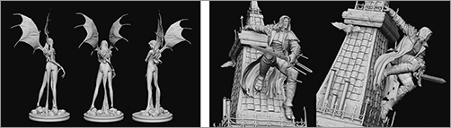
Image from www.alterton.com
3-D sculpture data can be easily printed, cast, and painted to create a high-quality collectible prototype in very little time. Figure 11-13 shows this process on two collectible statues by Alterton for Sideshow Collectibles.
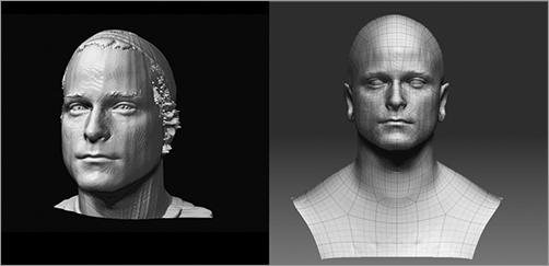
In addition to toys and collectibles, artists’ reference figures can also be created by loading scan data into ZBrush for cleanup and manipulation. Figure 11-14 shows a selection of 3-D reference prints I use daily. I keep these on my desk as constant sources of reference and inspiration. Many of these figures are taken directly from models that were body-scanned and then cleaned up in ZBrush before printing. The scanning process introduces many artifacts that need to be corrected before the data is usable. Figure 11-15 shows the before and after of using ZBrush standard sculpting and smoothing tools to help clean up a digital scan.
Figure 11-12: This collectible bust was created in ZBrush by Stefano Bernardi. The helmet is actually removable to reveal the character’s face. The Octogirl was sculpted in ZBrush by Chris Bostjanick before being printed in 3-D by Ownage.
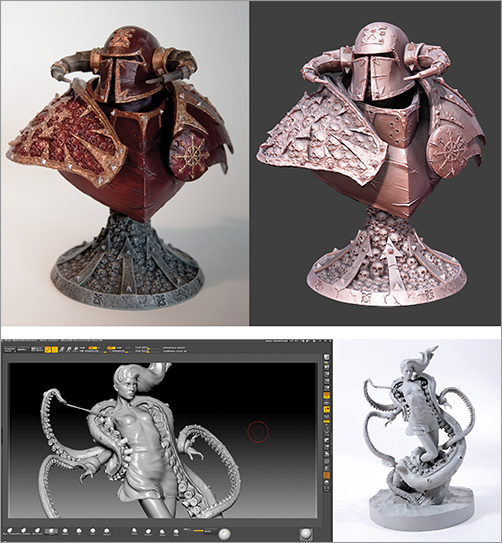
Figure 11-13: Alterton sculpted these prototypes in ZBrush for Sideshow Collectibles.
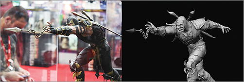
Image from www.alterton.com
Figure 11-14: These reference scans are based on 3-D scan data that has been cleaned and printed.
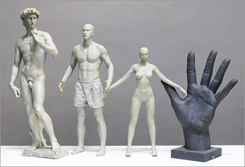
Figure 11-15: This head scan has been cleaned and prepared for printing using the standard sculpting and smoothing tools in ZBrush.
3-D Printing and Milling for Props and Manufacture
ZBrush is not limited to just organic models and small-scale maquettes. Artists have been using ZBrush and 3-D printing and milling to create monumental scale set pieces, sculptures, and props and costume elements.
Figure 11-16 shows a lion digitally sculpted by artist Bryn Court. Bryn’s digital sculpture was milled and then finished as a faux bronze set piece for the last Harry Potter film. Bryn is a fantastically talented traditional sculptor who is integrating ZBrush into his work as a film artist to cut down on time and increase his ability to generate high-quality work fast.
Figure 11-16: This lion was designed and sculpted in ZBrush by sculptor Bryn Court. The lion data was milled on a monumental scale and finished in clay before being molded and cast for use as a set piece.
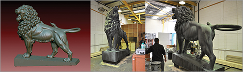
Courtesy of Bryn Court
As we have seen already, ZBrush is capable of creating complex machined surfaces with the new hard surface tools (Figure 11-17). As a result of this capability, ZBrush can be used to conceptualize and create prop designs using a 3-D mill.
Figure 11-17: This hard surface model was created entirely in ZBrush.
How Can I Get My Models Printed?
At this stage, you must be wondering how to get your own models printed. Luckily there are many companies today who are offering this service and the price is dropping. Usually prices are determined by the volume or height of the figure. Price can be lowered by printing the figure laying down rather than standing or by hollowing out the figure and cutting it into parts so it can be more efficiently placed on the printing tray. This means a figure laying down prints faster, but the build lines will be oriented lengthwise down the body.
The following list is a selection of companies who offer 3-D printing services to consumers. I had the Interdimensional Traveler 3-D print for this book printed by Ownage, and I can personally vouch for the exceptional quality of the print as well as the great customer service. I highly recommend you get in touch with them for your printing needs. Desmoda and team will stun you with their high-quality, fast work.
Ownage http://ownage.com/
GrowIt3D www.growit3d.com/
Morpheus www.facebook.com/morpheus.prototypes
Offload Studios http://www.offloadstudios.com/core/
Shapeways http://www.shapeways.com/
One day soon we will have desktop 3-D printing. The Objet company already has the Objet24 and Objet30 personal printers. These machines have a 28 micron layer thickness. That means they will print fine details but not as fine as the 16 µ layers by the Eden line of machines. It is only a matter of time before they become a consumer product. When this happens, manufacturing will be forever changed just like music and film were changed by MP3 and MP4 files. Imagine downloading a toy and printing unlimited copies from home. Imagine being able to scan and replace parts from your vintage toy collections by simply printing them. Imagine scanning your head with your webcam and printing a custom action figure head of yourself. These are all available technologies.
Prepare the Model for Printing
When printing a model on a 3-D printer, you have to ensure that your object is in print-ready condition. This means checking to see that the object meets certain physical requirements. We will take a look at each here.
“Watertightness”
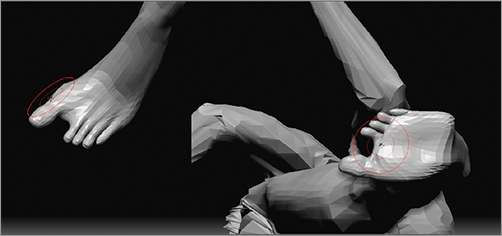
An object prepared for printing must be a closed surface as if it were watertight. That means there can be no holes in the 3-D model. For example, Figure 11-18 shows an arm with gloves on—the gloves have no thickness to them—they are only a single layer of polygons. Because of this, they will confuse the machine and will not print. We then see the same gloves with a thickness built in, in the form of an inner and outer shell—they are now objects with a volume that can be printed in the real world.
Figure 11-18: These gloves will not print because they are not solid volumes. The same gloves are corrected with a wall thickness, and this makes them real volumes that can be printed. Otherwise, a wall of polygons has no real-world thickness that can be replicated.
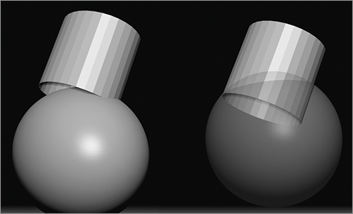
Sometimes you can resolve water-tightness issues by countersinking objects together. In Figure 11-19, for example, the cylinder is open on one end. These will not print because of the hole in the mesh. If you countersink it into the sphere, the mesh is now printable.
Figure 11-19: The cylinder here will not print because it is not water-tight. This can be resolved by countersinking the cylinder into the sphere until the hole is contained inside the volume of the sphere.
Workable File Sizes
In addition to being aware of the need for a thickness and watertightness in your models, you must also be aware of file sizes. Many 3-D printers have a file-size limit for the software. This limit improves with each machine but generally an OBJ with many millions of polygons can easily weigh in at hundreds of megabytes of data, whereas an average file-size limit for the printer software might be around 200 megs. You can also speed up the printing process and reduce the chance of the printer crashing in the middle of the process if the file sizes are smaller.
To deal with this discrepancy between file size and software limits on the machine, you will need to decimate the models. Decimation allows the computer to remove polygons in areas of low detail while leaving them in areas of high detail (Figure 11-20). This means you retain all of your fine detail while lowering the overall poly count and file size. As we saw in Chapter 9, “Painting the Forest Spirit,” ZBrush uses the plug-in Decimation Master to accomplish this, and we will take a detailed look at it later in this chapter.
Figure 11-20: Here you can see the impact on decimation to the poly count. When performed correctly, the decimation process does not impact the fine details. The head on the left is 1 million faces while the one on the right is decimated to 200 thousand.
Finally, models for 3-D printing need to obey the rules of physical objects. For example, you cannot have floating arms and legs that don’t connect to the torso. You also want to avoid very thin or tiny protrusions, as these may not print. Or if they do, they are likely to be very fragile.
In this section, we will return to the Interdimensional Traveler character. Because we will now be using the model as a final 3-D print and not as the basis for an illustration, we will need to resolve the unfinished areas into a final maquette—we will adjust the pose to work in the round and look at how to compose for 3-D space. We will then decimate and export data suitable for 3-D printing. Let’s get started.
Reconsider the Model as a 3-D Object
In the initial stages of sculpting the Interdimensional Traveler, we took some shortcuts since we knew the design would be painted in Photoshop. Now we have a chance to revisit and resolve the figure in the round. This includes detailing areas we merely suggested before, like the legs, which we knew would fall into shadow. We will also try to redesign some aspects, such as the feet, to make them feel even more alien.
Readdressing the Back and Scapulae
At this phase, we will start to address some areas that were underdeveloped in the initial sculpt. The back, for instance, needs to be resolved since it was not part of the original illustration.
1. Open the roughsculpt.zpr ZBrush project file from the DVD or download files. From the back view, I start to resolve the shoulder blades (Figure 11-21). The back has been distorted in the process of posing and sculpting the figure for viewing from the front. This was acceptable since we were concerned with quickly creating a 2-D concept image. Now that we need to create a 3-D maquette, we need to resolve areas like this one.
2. The scapulae will swing up and out as an arm is raised, and back toward the middle of the back as the arms are brought back (Figure 11-22). With this in mind, I introduce these forms to the back (Figure 11-23).
Figure 11-21: The back of the figure is not fully resolved in the original sculpture. We will need to correct the scapulae.
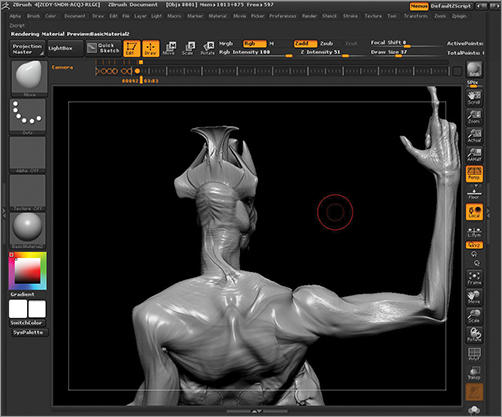
Figure 11-22: Scapulae in motion—skeleton reference
3. Create the impression of skin stretching across the shoulder blades with the Clay Tubes brush. As we have done before, select claytubes and turn off the alpha. Dial down the draw size and stoke across the borders of the scapulae. It will fill into the recessed areas and create the look of skin in tension stretched over bone (Figure 11-24).
4. Since this figure has four sets of arms, we need to make sure to address the second set of scapulae. Using the Standard brush, I sketch in the borders of the shoulder blades (Figure 11-25). A key landmark on a back as sinewy as this would be the traces of the spine. Using the Standard brush I suggest the spinous processes of the vertebrae down the length of the back. This helps reinforce the sense this creature has a very emaciated figure and very thin skin tissue (Figure 11-26).
Figure 11-23: Sculpting the scapulae
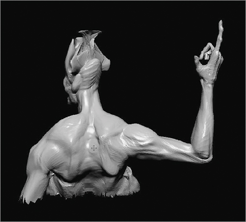
Figure 11-24: Using the claytubes brush to suggest skin stretching over the bony structure of the scapulae

Figure 11-25: Because this character has four arms, we need to be sure the secondary set of arms has a fully resolved pair of scapulae to allow them to move like the upper arms.

Figure 11-26: Here I have added in the suggestion of the vertebrae to give the back an even more emaciated appearance. In image a, you can see the scapulae and spine marked in red. In image b, you can see the sculpted spine and scapulae.

In addition to the edits above, I make a few more changes to the anatomy of the figure. Major alterations are made to the buttocks and hands. To see these changes please review the video on the DVD or download files, which shows the edit process narrated in full. We will now move on to the biggest alteration in the design, the feet.
The Feet
Up until now, the feet were left unresolved in the design. In the original illustration, the legs fall into shadow to allow the focal point to be on the chest, arms, and head. At this point we need to revisit the legs and feet and determine what kind of feet this character will have. I defaulted to a normal human foot shape originally, but this is not something I want to carry into the final design. Since the figure has such a long graceful flow to the stance and proportion, I want a foot design based on a dog leg—a foot that stands on its toe. This leg design is called digitigrade. A digitigrade is an animal that stands or walks on its digits, or toes (Figure 11-27).
Another benefit to this foot form is that it can lengthen the leg even further, giving a more beautiful sweep to the lower body (Figure 11-28). Follow these steps to create the same foot design. To see this process in full, check the video included on the DVD or download files.
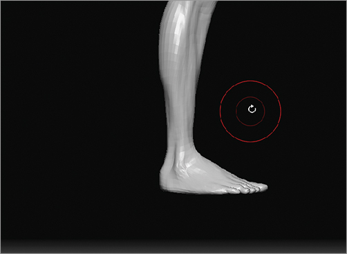
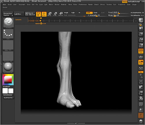
1. Orient the feet to be center screen. Turn on X symmetry by pressing the X key and turn off perspective by pressing the P key (Figure 11-29).
Figure 11-27: This illustration shows the internal structure of a digitigrade leg.

Figure 11-28: Changing the foot design lengthens the graceful sweep of the lower leg even more.
Figure 11-29: Center the feet on screen.
2. Use transpose masking to mask down to the ankle (Figure 11-30). Orient the transpose line so the last circle is over the ankle. Press R to enter Rotate mode and while holding Alt + Click + drag in the circle to bend the foot down. Alt + Click + dragging in the last circle will activate “bone posing,” which allows you to bend the ankle without the mesh collapsing.
3. Extend the mask to the middle of the foot itself. Drag the last transpose circle down to the point where the mask ends (Figure 11-31). Use the same Alt + Click + drag technique to rotate the foot at this angle. I also press W to switch to move mode and shift the toes further down.
4. Using the Move brush, the foot form is further stretched. The ankle and calf are also slightly enlarged to compensate for the longer taper to the leg (Figure 11-32).
Figure 11-30: Masking to the ankle the bending with Transpose Rotate
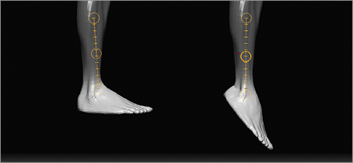
Figure 11-31: Extend the mask further down the foot to help manipulate the toe shape. Use transpose to shift the toes further from the ankle.
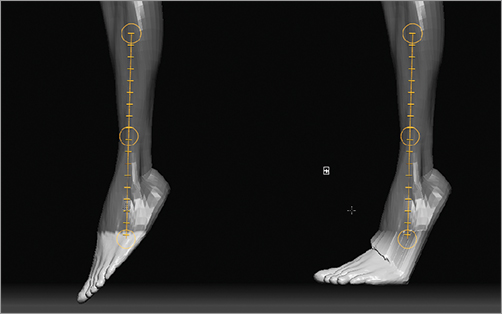
Figure 11-32: Subtle changes are made to the foot and calf muscles with the Move brush.

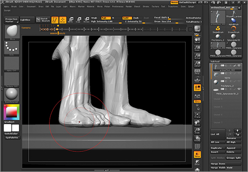
At this stage, the basic foot form is roughed in. We will now turn our attention to the toes. I want to spread the big toe from the others and create a more simian- or chimp-like foot configuration. This gives the impression the foot can grasp or clamp on to surfaces. The other toes are squashed back, making the foot even more inhuman in appearance (Figure 11-33). Follow these steps to create the same look.
1. Step down to the lowest subdivision level so that you have fewer faces to manipulate. We will be making big changes to the foot so detail is unnecessary right now. Mask the leg down to the big toe (Figure 11-34). You may find it helpful to hide the rest of the model except for the feet since our attention will be on this area. Make sure X symmetry is on.
2. Using the Move brush and the Transpose Move tool shift the big toe out from the other digits (Figure 11-35). Rotating to the bottom view will allow you to get a clearer idea of the overall form of the food pad. Shape the toes and the base of the foot from this view as well.
Figure 11-33: The foot is shaped into a less human form as seen here.
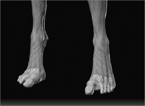
Figure 11-34: Isolate the big toe with a mask.

Figure 11-35: Shifting the big toe away from the other digits and working the shape of the foot from the bottom view
3. At the ankle, use the Move brush to pull out a claw appendage. This is a kind of vestigial toe that helps add interest to this part of the anatomy and adds another sharp, aggressive element (Figure 11-36). This appendage is suggestive of a dog’s dewclaw.
4. At this stage, I need to readdress the calves to site better with this new foot design. As you can see in Figure 11-37, the shape of the calves feels rather uninspired and dull. I select the move brush to alter the overall silhouette of this shape. I will rework the silhouette of the back of the legs to create a more unified rhythm of lines flowing down into the foot. Using the Move brush, I create a crest in the back of the calf muscle. This sharp line break creates a nice counterbalance to the sweep of the front of the leg (Figure 11-38).
5. Select the Standard brush. We will now start to create the skeletal and muscular anatomy of the foot. As it stands, there is little detail to the forms there, so we need to add secondary shapes to suggest the underlying skeletal and muscular anatomy to add realism to the form. With the Standard brush, sketch in the space between the tarsal bones of the foot (Figure 11-39).
Figure 11-36: Create a claw form at the ankle.
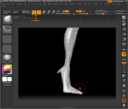
Figure 11-37: Altering the shape of the legs with the Move brush, then pulling out the calf muscles to create a sharper crest in the silhouette

Figure 11-38: The sweep on the leg from the front is counterbalanced nicely with the crest and break created by the sharper calf silhouette on the back of the leg.
Figure 11-39: Sketch in the suggestion of the tarsal bones with the Standard brush.
6. To add a sense of skin stretching across those bones, use the Standard brush. Dial down the draw size and stroke across the tarsal bone forms. This will start to create a series of raised ridges crossing the tarsal bones, which can be resolved into skin. Step up to a higher subdivision level and continue to sketch in raised wrinkles. These will read like tissue skin over the larger bony forms (Figure 11-40).
Figure 11-40: Smaller standard brush strokes across the bony forms help suggest wrinkled skin.

Posing for 3-D
This section required that Transpose Master be installed. Transpose Master is a free plug-in from Pixologic for posing models with multiple SubTools. Download and install the files from www.pixologic.com before attempting this section.
In this section, we will repose the figure to be viewed in the round. This is different than posing for a single view because a sculpture, unlike an image, is experienced through a full 360 degrees. We will use a spiral composition for this figure.
Spiral composition is a method of positioning a figure where the masses are each oriented slightly rotated along the Y axis, for example, if the pelvis is facing forward, the shoulders are slightly turned, and the head is turned further (Figure 11-41). This creates a composition where each mass is incrementally turned, which helps create a sense of motion and interest even in a seated or standing pose. This works particularly well for sculpture since it creates interesting shapes throughout 360 degrees of view (Figure 11-42). The steps below show how I use Transpose Master to pose this figure in a spiral composition.
Figure 11-41: These masses are arranged in a spiral composition.
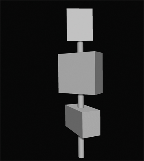
Figure 11-42: The character in spiral composition. Note the offset between each red axis line through the figure.

We will be using Transpose Master to create this pose. Transpose Master allows you to easily pose characters with multiple SubTools by creating a single proxy mesh that contains all the elements in one model. The pose data is then transferred back to the original model retaining each SubTool. To get the best result, I find it is best to make sure the lowest subdivision level has a fair bit of geometry to support the pose deformation. Transpose Master will create a proxy mesh from the lowest subdivision level of the model. This ZTool has far too little geometry in the hips to support the twisting pose I want to create (Figure 11-43). The figure on the left represents subdivision level 1 while the right is level 3. I want to make level 3 the lowest subdivision level as it has just enough geometry to support thee kinds of pose deformations I need to create.
Figure 11-43: In level 1 on the left, there is too little geometry in the waist to support deformation required. Level 3 on the right is a far better resolution for posing.

1. Step up to level 3. Form the Tool Geometry menu click Delete Lower to remove the unneeded lower subdivision levels (Figure 11-44). This will only work if you have no layers in Record mode. If this action fails, be sure to exit Record mode on any layers. You exit record mode by clicking to the right of the record icon. This enables the eyeball icon placing the layer in visible mode with record off. If possible, you may want to collapse any layers you have on the model. Step up to the highest subdivision level and bake the layers by pressing the Bake All button (Figure 11-45). This will permanently apply the layer contents to the model. If you prefer to keep your layers, just make sure to exit record mode on any layers currently active.
Figure 11-44: Delete the lower subdivision levels
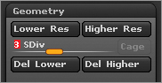
Figure 11-45: The Bake All button

2. This creates a level 1 with 102k faces. What’s more important than the total face count is the fact the geometry is concentrated in areas like the waist, which I will need to twist to create the pose I want.
3. Start Transpose Master by pressing ZPlugin Transpose Master TPoseMesh to create the Posable proxy mesh (Figure 11-46).
Figure 11-46: Create the Posable mesh.

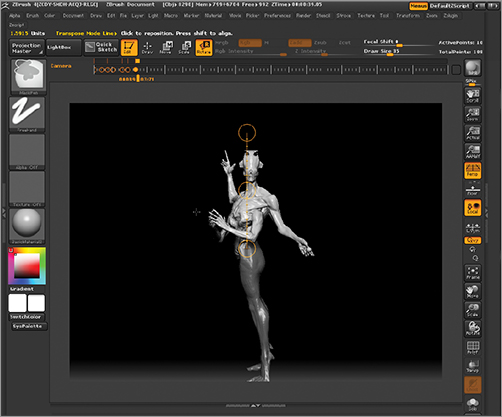
Once the model is in TPose, you can use the Transpose tools to pose it. I chose to rotate the torso around the Y axis as well as bring one of the legs back slightly to suggest the anticipation of a forward motion, as if the character might be about to take a step. Follow these steps to create this pose (Figure 11-47).
1. Press R to enter Transpose Rotate mode. Press Ctrl + Click + drag down the model’s torso to mask the upper body. Rotate around the figure to be sure everything above the waist is masked. Manually mask in any missed areas (Figure 11-48).
2. Ctrl + Click on the background to invert the mask. Ctrl + Click on the mask itself to feather soften the edge. Press R to enter Transpose Rotate mode and draw a transpose line up the center of the back (Figure 11-49).
3. Rotate to the side view. Click and drag the transpose line to the centerline of the body by clicking on the circle or line itself. Once the line is placed, click and drag inside the center circle to rotate the torso around the Y axis (Figure 11-50).
Figure 11-47: The posed figure
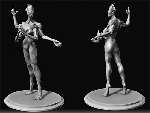
Figure 11-48: Isolate the upper torso with transpose masking and then manually mask out any missed areas.
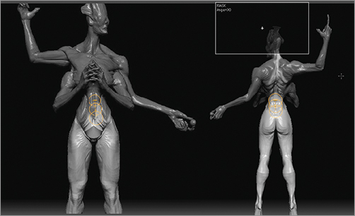
Figure 11-49: Invert the mask and draw a transpose rotate line up the center of the back.
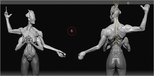
Figure 11-50: Rotate the torso around the Y axis.
Next we will rotate the legs. We will begin by moving the right leg slightly back from the left. Isolate the right leg so the body is masked and the leg is unmasked. Using the masking pen, adjust the mask edge so it runs along the pelvic bone and the glute muscle is unmasked as well (Figure 11-51).
Draw a transpose line from the hip to the knee. Rotate the leg back slightly. Move the transpose line inside the leg from the front view (Figure 11-52). Click and drag in the center circle to rotate the leg around the Y axis. This rotates the leg in the hip joint and helps make the two feet point down different axes (Figure 11-53)—this helps create a more grounded and natural stance.
Figure 11-51: Isolate the right leg with a mask, then manually unmask the glute muscle so it will be included in the deformation.

Figure 11-52: Rotate the leg back slightly and from the front view, shift the transpose line inside the leg.

Figure 11-53: The feet are now oriented down in slightly offset directions. This helps create a more stable stance.

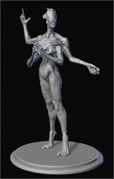
This completes the pose for the character—notice how the figure suggests a forward motion while at the same time offering an interesting view from each side (Figure 11-54). We will now move on to making a base.
Figure 11-54: The final pose

Create a Base
The figure will need a base so it can stand on a table without danger of toppling over. While it is possible to create such a figure that stands free, a base also allows you the chance to suggest some environment for the character and add other elements. To see this process in detail, please see the video on the DVD or download files.
1. The simplest approach to making a base is to use the ZBrush primitives. With the final posed ZTool open in ZBrush, go to the Tool menu and press the Tool Palette button (Figure 11-55).
2. From the tool palette, select the Sphereinder ZTool. This will replace the maquette as the active tool in the document window.
3. We will need to edit the shape of the Sphereinder to better serve as a base. As of right now, this is not a polygon mesh, it is a ZBrush primitive that has settings under the Tool menu to control its shape and size. Open Tool Initialize to access the shape controls (Figure 11-56).
4. In the Initialize menu, set the ZSize slider to 15, the TRadius slider to 63, and the TCurve to 50 (Figure 11-57). Convert this to an editable polygon mesh by pressing the Make Polymesh 3-D button under the Tool menu (Figure 11-58). This will create a polygon version of the tool named PM3D_Sphereinder. ZBrush will automatically select the PM3D version of the Sphereinder. We will need to make one more variant of the tool, so be sure to reselect the ZBrush primitive Sphereinder ZTool from the Tool menu. You can easily identify the ZBrush primitive version of the Sphereinder, as it is the one that does not have PM3D_ at the start of the filename (Figure 11-59).
5. Alter the Initialize settings now to the following values: ZSize 5, TRadius 10, and TCurve 100. Click Make Polymesh 3-D to make a poly version of the model. From the Tool menu, select the figure. From the SubTool menu append both PM3D_spheriencer ZTools (Figure 11-60).
6. Hide the other SubTools but the two Sphereinder tools. One of the two Sphereinder disc tools will have a rounded top while the other will be more of a squat flat-topped disc. Select the one with the rounded top and, using the Transpose Move brush, shift it down from the flat top Sphereinder (Figure 11-61).
Figure 11-55: Open the Tool palette
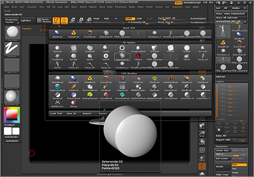
Figure 11-56: Open the Initialize menu to access the shape controls.

Figure 11-57: Here, you can see the effect of the setting changes.
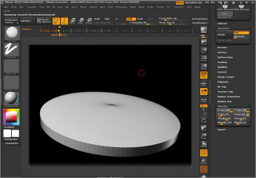
Figure 11-58: The make PolyMesh 3-D button

Figure 11-59: Select the primitive Sphereinder again—the tool outlined in red is the ZPrimitive, and the others are polymesh copies, as you can tell from the PM3D_ in the filename.

Figure 11-60: Both Sphereinder polymeshes appended

Figure 11-61: Move the Sphereinder with the rounded tip down and away from the second Sphereinder
7. Rotate to the top view. Select the flat top d and press E for Transpose Scale. Draw a transpose line from the center of the Sphereinder. I turn on frame mode to make it easier to spot the center. Scale the Sphereinder down (Figure 11-62).
8. Use Transpose Move to countersink the top disc into the larger base (Figure 11-63). The bottom Sphereinder may protrude because of its convex top. If so, simply use the Clay Tubes brush to push any exposed areas back (Figure 11-64).
9. Merge the two Sphereinders together by selecting the upper Sphereinder SubTool and pressing the Merge Down button under the Tool SubTool menu (Figure 11-65). Select OK from the popup window (Figure 11-66). Using the Transpose tools, reorient the base under the character’s feet (Figure 11-67).
10. To make the feet contact the base, turn on transparency (Figure 11-68). Use the Move brush to shift the pads of the feet to appear to contact the surface of the base (Figure 11-69).
Figure 11-62: Scale the flatter Sphereinder down.

Figure 11-63: Countersink the top Sphereinder into the base.

Figure 11-64: The final base

Figure 11-65: Merge the two base parts down into one SubTool.

Figure 11-66: Select OK from the popup menu.

Figure 11-67: Orient the base under the character’s feet using the Transpose Move and Rotate tools.
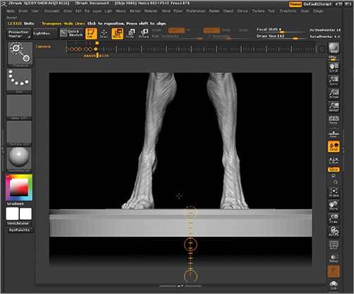
Figure 11-68: Enable transparency and turn off ghost mode
Figure 11-69: Using the Move brush, shape the pads of the feet to the base. Transparency mode allows you to grab the parts of the feet hidden inside the base.
Exporting the Geometry for Print
We will now export the geometry for print. Remember that 3-D printers do have a file-size limit. If you were to decimate the subdivision levels to make a smaller file, you would lose resolution—we want to keep detail while lowering file size. Luckily, Pixologic has a free plug-in to do just that— it is called Decimation Master. They also have the 3-D print exporter to allow you to export STL files at a real-world size.
Decimating the Figure
Decimation Master and 3D Print Exporter are both available from Pixologic.com for free download. Extract them into the ZStartup/ZPlugs folder and restart ZBrush to access them. Here, we discuss how to use Decimation Master.
Before you can complete this section, you need to be sure Decimation Master and 3D Print Exporter are installed.
1. From the DVD or download files, open the ZBrush project posed.zpr.
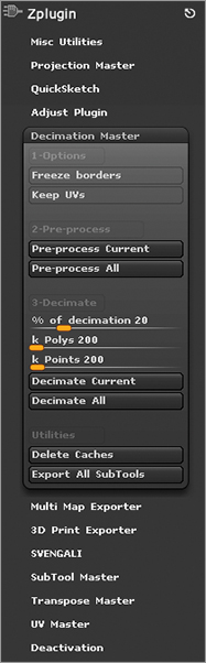
2. The project will open with the final posed figure including the base and all SubTools. Open the Decimation Master plug-in by clicking ZPlugs Decimation Master (Figure 11-70). Click the radial button in the ZPlugin menu to dock it to the side of the screen for easier access to the settings.
Figure 11-70: Open the Decimation Master menu. Dock it to the side of the screen.
3. Before any model can be decimated, ZBrush must preprocess it to determine the most efficient way to reduce the poly count while retaining details. This figure has multiple SubTools, but only the figure will require decimation. The sphere, base, and teeth are low enough not to require reduction. With the figure SubTool in edit mode, step up to the highest subdivision level.
4. From the Decimation Master menu, click the Preprocess Current button. Note that we are only decimating the figure—if you have multiple SubTools to decimate you will click Preprocess All. ZBrush will examine the geometry of the figure and write a cache file on disk for use when it decimates later. This may take some time. When it is complete, you will be able to use the decimation settings to reduce the model.
5. Decimation Master allows three methods of specifying a level of decimation. The three sliders in Figure 11-71 illustrate each of these options. The first slider takes a percentage, the second takes a projected face count, and the third is a projected point count.
Figure 11-71: The decimation control sliders allow you to define the amount of decimation by percentage, either by thousands of polys (faces), or thousands of points.

7. I find the second slider, number of polys, to be the easiest to use. Generally I will try to keep my mesh around 1 million faces. Since this slider reads in 100k faces, a setting of 200 equals 200,000 faces. I set this slider to 500 for 500,000 faces.
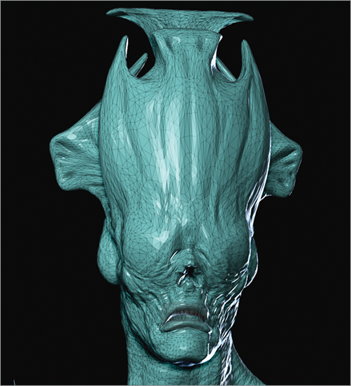
8. Press the Decimate Current button and ZBrush will reduce the model as per your settings. Decimation involves triangulating all the faces of the model, then removing triangles in areas of low detail, and retaining them in areas of high detail. Figure 11-72 shows the figure before and after this decimation operation. The model looks nearly identical. If you look in wireframe (Figure 11-73), you can see how the mesh has been triangulated and reduced in areas of low detail.
Figure 11-72: The model before and after decimation
Figure 11-73: A wireframe view of the decimated mesh shows how the quads have been triangulated and areas of low detail reduced.
9. At this stage, the figure is decimated and ready for export. You can manually export an OBJ by going to Tool Export and saving an OBJ file. You will want to export an OBJ for each SubTool, including the sphere, base, and teeth. Each object will export in the correct position in space so they will reload together correctly in the printer company’s software.
10. Save your ZTool by going to Tool Save As and naming the file “figure_decimated.ztl.”
As an alternative to the last exporting step, you can use the 3D Print Exporter plug-in for even more control. In the next section, we will look at how to export with 3D Print Exporter.
3-D Print Exporter
The 3-D Print Exporter plug-in allows you to export OBJ and STL files from ZBrush for use on a 3-D printer. What makes this plug-in particularly useful is that it allows you to specify an object scale in real-world units, so you can be sure of the object size when it is being sent to the 3-D printer. In the following steps, we will export the figure as both STL binary and ASCII files.
1. From the ZPlugin menu, open the 3D Print Exporter menu (Figure 11-74).
Figure 11-74: The 3D Print Exporter plug-in

2. If it is not still open, load the decimated ZTool from the previous section.
3. Because the figure consists of several SubTools, we will want to export them all as a single model. Under the section of the plug-in marked 3 Export, enable the All button on the 3-D Print Exporter menu. This will scale and export all the SubTools as a single mesh (Figure 11-75).
4. We will need to reset the size ratios for all the SubTools. To do this, click the Update Size Ratios button (Figure 11-76). Once ZBrush has determined the size ratio between all the buttons, it will enable you to specify a new size in the next step.
Figure 11-75: Enable the All button to export all SubTools as one.
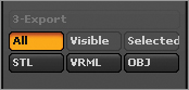
5. Select a unit from the two buttons: in. or mm. Most printing companies prefer to work in metric units, but imperial units (inches and feet) will be fine. The stl file has no internal units, so you will need to tell the printer what measurement and unit type you used.
6. I want to export a figure that is 12 inches high. Set the height slider to 12 and press enter.
7. To export an STL file, press the STL button in the Export section of the interface (Figure 11-77). ZBrush will request a filename and export the SubTools as a single STL file. This file can be sent to the 3-D printer or the printing company for output. Some companies will offer a web interface for uploading your data. See the list of service providers earlier in this chapter for companies that can print your figure.
Figure 11-76: Update size ratios
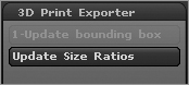
Figure 11-77: Click the STL button to export a binary STL file of all your decimated tools.

STL binary is the default STL file format. STL binary is the best option as it exports smaller files. Neither STL format supports UVs or textures. VRML will export a model that has a texture and UVs applied to it. This format is ideal for color-printing purposes on machines like the ZCorp, which will print a texture on the model. If you have polypaint on the model and the printer will support vertex RGB, use the ExpColors option to export colored vertices. If you need to export an STL ASCII format, this can be enabled under the Advanced Options of the plug-in.
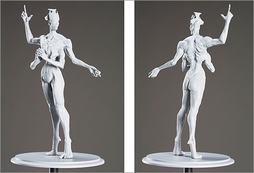
That completes this chapter on 3-D printing and ZBrush. We have seen how to use ZBrush as a tool in conjunction with 3-D printing and milling technology to create physical sculptures on the real world. We have seen the various applications of 3-D printing from concept design to fine art to toys and collectibles. Figure 11-78 shows the final 3-D print produced by Ownage.
Figure 11-78: This 3-D print was produced by ownage.com—Ownage supplies the best quality for the lowest prices for all your 3-D printing and casting requirements. This figure has been molded for multiple castings.