Day 28 Connecting Switches and Ethernet Technology
CCNA 640-802 Exam Topics
![]() Explain the technology and media access control method for Ethernet networks.
Explain the technology and media access control method for Ethernet networks.
![]() Select the appropriate media, cables, ports, and connectors to connect switches to other network devices and hosts.
Select the appropriate media, cables, ports, and connectors to connect switches to other network devices and hosts.
Key Topics
Ethernet has continued to evolve from the 10BASE2 flavor capable of speeds up to 185 Mbps to the newest 10GigE (10 Gigabit Ethernet) capable of speeds up to 10 Gbps. Since 1985, IEEE has continued to upgrade the 802.3 standards to provide faster speeds without changing the underlying frame structure. This feature, among others, has made Ethernet the choice for LAN implementations worldwide. Today we review Ethernet technologies and operation at both the data link and physical layer.
Ethernet Overview
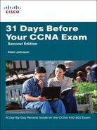
802.3 is the IEEE standard for Ethernet, and both terms are commonly used interchangeably. The terms Ethernet and 802.3 both refer to a family of standards that together define the physical and data link layers of the definitive LAN technology. Figure 28-1 shows a comparison of Ethernet standards to the OSI model.
Ethernet separates the functions of the data link layer into two distinct sublayers:
![]() Logical Link Control (LLC) sublayer: Defined in the 802.2 standard.
Logical Link Control (LLC) sublayer: Defined in the 802.2 standard.
![]() Media Access Control (MAC) sublayer: Defined in the 802.3 standard.
Media Access Control (MAC) sublayer: Defined in the 802.3 standard.
The LLC sublayer handles communication between the network layer and the MAC sublayer. In general, LLC provides a way to identify the protocol that is passed from the data link layer to the network layer. In this way, the fields of the MAC sublayer are not populated with protocol type information, as was the case in earlier Ethernet implementations.
The MAC sublayer has two primary responsibilities:
![]() Data Encapsulation: Includes frame assembly before transmission, frame parsing upon reception of a frame, data link layer MAC addressing, and error detection.
Data Encapsulation: Includes frame assembly before transmission, frame parsing upon reception of a frame, data link layer MAC addressing, and error detection.
![]() Media Access Control: Because Ethernet is a shared media and all devices can transmit at any time, media access is controlled by a method called Carrier Sense Multiple Access with Collision Detection (CSMA/CD).
Media Access Control: Because Ethernet is a shared media and all devices can transmit at any time, media access is controlled by a method called Carrier Sense Multiple Access with Collision Detection (CSMA/CD).
At the physical layer, Ethernet specifies and implements encoding and decoding schemes that enable frame bits to be carried as signals across both unshielded twisted-pair (UTP) copper cables and optical fiber cables. In early implementations, Ethernet used coaxial cabling.
Legacy Ethernet Technologies
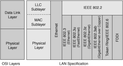
Ethernet is best understood by first considering the two early Ethernet specifications—10BASE5 and 10BASE2. With these two specifications, the network engineer installs a series of coaxial cables connecting each device on the Ethernet network, as shown in Figure 28-2.
The series of cables creates an electrical circuit, called a bus, which is shared among all devices on the Ethernet. When a computer wants to send some bits to another computer on the bus, it sends an electrical signal, and the electricity propagates to all devices on the Ethernet.
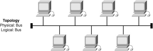
With the change of media to UTP and the introduction of the first hubs, Ethernet physical topologies migrated to a star as shown in Figure 28-3.
Regardless of the change in the physical topology from a bus to a star, hubs logically operate similar to a traditional bus topology and require the use of CSMA/CD.
CSMA/CD
Because Ethernet is a shared media where every device has the right to send at any time, it also defines a specification for how to ensure that only one device sends traffic at a time. The CSMA/CD algorithm defines how the Ethernet logical bus is accessed.
CSMA/CD logic helps prevent collisions and also defines how to act when a collision does occur. The CSMA/CD algorithm works like this:
-
A device with a frame to send listens until the Ethernet is not busy.
-
When the Ethernet is not busy, the sender(s) begin(s) sending the frame.
-
The sender(s) listen(s) to make sure that no collision occurred.
-
If a collision occurs, the devices that had been sending a frame each send a jamming signal to ensure that all stations recognize the collision.
-
After the jamming is complete, each sender randomizes a timer and waits that long before trying to resend the collided frame.
-
When each random timer expires, the process starts again from the beginning.
When CSMA/CD is in effect, it also means that a device’s network interface card (NIC) is operating in half-duplex mode—either sending or receiving frames. CSMA/CD is disabled when a NIC autodetects that it can operate in—or is manually configured to operate in—full duplex mode. In full duplex mode, a NIC can send and receive simultaneously.
Legacy Ethernet Summary
Today, you might occasionally use LAN hubs, but you will more likely use switches instead of hubs. However, keep in mind the following key points about the history of Ethernet:
![]() The original Ethernet LANs created an electrical bus to which all devices connected.
The original Ethernet LANs created an electrical bus to which all devices connected.
![]() 10BASE2 and 10BASE5 repeaters extended the length of LANs by cleaning up the electrical signal and repeating it—a Layer 1 function—but without interpreting the meaning of the electrical signal.
10BASE2 and 10BASE5 repeaters extended the length of LANs by cleaning up the electrical signal and repeating it—a Layer 1 function—but without interpreting the meaning of the electrical signal.
![]() Hubs are repeaters that provide a centralized connection point for UTP cabling—but they still create a single electrical bus, shared by the various devices, just like 10BASE5 and 10BASE2.
Hubs are repeaters that provide a centralized connection point for UTP cabling—but they still create a single electrical bus, shared by the various devices, just like 10BASE5 and 10BASE2.
![]() Because collisions could occur in any of these cases, Ethernet defines the CSMA/CD algorithm, which tells devices how to both avoid collisions and take action when collisions do occur.
Because collisions could occur in any of these cases, Ethernet defines the CSMA/CD algorithm, which tells devices how to both avoid collisions and take action when collisions do occur.
Current Ethernet Technologies
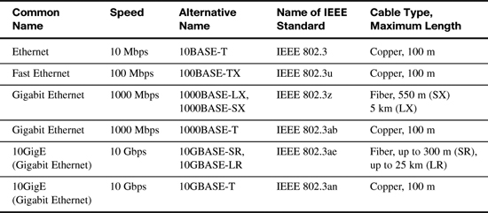
Refer back to Figure 28-1 and notice the different 802.3 standards. Each new physical layer standard from the IEEE requires many differences at the physical layer. However, each of these physical layer standards uses the same 802.3 header, and each uses the upper LLC sublayer as well. Table 28-1 lists today’s most commonly used IEEE Ethernet physical layer standards.
UTP Cabling
The three most common Ethernet standards used today—10BASE-T (Ethernet), 100BASE-TX (Fast Ethernet, or FE), and 1000BASE-T (Gigabit Ethernet, or GE)—use UTP cabling. Some key differences exist, particularly with the number of wire pairs needed in each case and in the type (category) of cabling.
The UTP cabling used by popular Ethernet standards include either two or four pairs of wires. The cable ends typically use an RJ-45 connector. The RJ-45 connector has eight specific physical locations into which the eight wires in the cable can be inserted, called pin positions or, simply, pins.
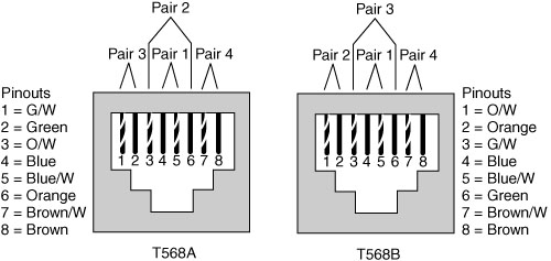
The Telecommunications Industry Association (TIA) and the Electronics Industry Alliance (EIA) define standards for UTP cabling, color coding for wires, and standard pinouts on the cables. Figure 28-4 shows two TIA/EIA pinout standards, with the color coding and pair numbers listed.
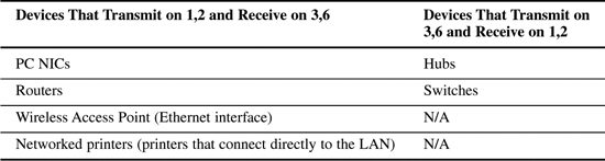
For the exam, you should be well prepared to choose which type of cable (straight-through or crossover) is needed in each part of the network. In short, devices on opposite ends of a cable that use the same pair of pins to transmit need a crossover cable. Devices that use an opposite pair of pins to transmit need a straight-through cable. Table 28-2 lists typical devices and the pin pairs they use, assuming that they use 10BASE-T and 100BASE-TX.
1000BASE-T requires four wire pairs because Gigabit Ethernet transmits and receives on each of the four wire pairs simultaneously.
However, Gigabit Ethernet does have a concept of straight-through and crossover cables, with a minor difference in the crossover cables. The pinouts for a straight-through cable are the same—pin 1 to pin 1, pin 2 to pin 2, and so on. The crossover cable crosses the same two-wire pair as the crossover cable for the other types of Ethernet—the pair at pins 1,2 and 3,6—as well as crossing the two other pairs (the pair at pins 4,5 with the pair at pins 7,8).
Benefits of Using Switches
A collision domain is a set of devices whose frames could collide. All devices on a 10BASE2, 10BASE5, or any network using a hub risk collisions between the frames that they send, so all devices on one of these types of Ethernet networks are in the same collision domain and use CSMA/CD to detect and resolve collisions.
LAN switches significantly reduce, or even eliminate, the number of collisions on a LAN. Unlike hubs, switches do not create a single shared bus. Instead, switches do the following:
![]() Switches interpret the bits in the received frame so that they can typically send the frame out the one required port, rather than all other ports.
Switches interpret the bits in the received frame so that they can typically send the frame out the one required port, rather than all other ports.
![]() If a switch needs to forward multiple frames out the same port, the switch buffers the frames in memory, sending one at a time, thereby avoiding collisions.
If a switch needs to forward multiple frames out the same port, the switch buffers the frames in memory, sending one at a time, thereby avoiding collisions.
In addition, switches with only one device cabled to each port of the switch allow the use of full-duplex operation. Full-duplex means that the NIC can send and receive concurrently, effectively doubling the bandwidth of a 100 Mbps link to 200 Mbps—100 Mbps for sending and 100 Mbps for receiving.
These seemingly simple switch features provide significant performance improvements as compared with using hubs. In particular:
![]() If only one device is cabled to each port of a switch, no collisions can occur.
If only one device is cabled to each port of a switch, no collisions can occur.
![]() Devices connected to one switch port do not share their bandwidth with devices connected to another switch port. Each has its own separate bandwidth, meaning that a switch with 100 Mbps ports has 100 Mbps of bandwidth per port.
Devices connected to one switch port do not share their bandwidth with devices connected to another switch port. Each has its own separate bandwidth, meaning that a switch with 100 Mbps ports has 100 Mbps of bandwidth per port.
Ethernet Addressing
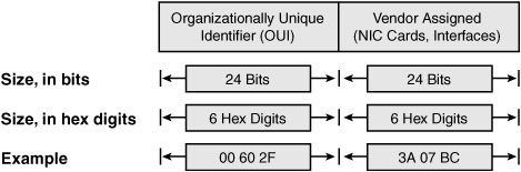
The IEEE defines the format and assignment of LAN addresses. To ensure a unique MAC address, the first half of the address identifies the manufacturer of the card. This code is called the organizationally unique identifier (OUI). Each manufacturer assigns a MAC address with its own OUI as the first half of the address. The second half of the address is assigned by the manufacturer and is never used on another card or network interface with the same OUI. Figure 28-5 shows the structure of a unicast Ethernet address.
Ethernet also has group addresses, which identify more than one NIC or network interface. The IEEE defines two general categories of group addresses for Ethernet:
![]() Broadcast addresses: The broadcast address implies that all devices on the LAN should process the frame and has a value of FFFF.FFFF.FFFF.
Broadcast addresses: The broadcast address implies that all devices on the LAN should process the frame and has a value of FFFF.FFFF.FFFF.
![]() Multicast addresses: Multicast addresses are used to allow a subset of devices on a LAN to communicate. When IP multicasts over an Ethernet, the multicast MAC addresses used by IP follow this format: 0100.5exx.xxxx, where any value can be used in the last half of the address.
Multicast addresses: Multicast addresses are used to allow a subset of devices on a LAN to communicate. When IP multicasts over an Ethernet, the multicast MAC addresses used by IP follow this format: 0100.5exx.xxxx, where any value can be used in the last half of the address.
Ethernet Framing
The physical layer helps you get a string of bits from one device to another. The framing of the bits allows the receiving device to interpret the bits. The term framing refers to the definition of the fields assumed to be in the data that is received. Framing defines the meaning of the bits transmitted and received over a network.
The framing used for Ethernet has changed a couple of times over the years. Each iteration of Ethernet is shown in Figure 28-6, with the current version shown at the bottom.
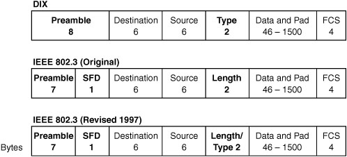
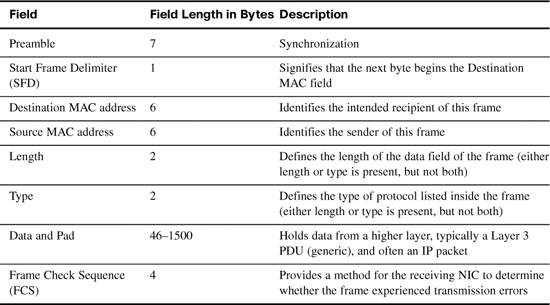
The fields in the last version shown in Figure 28-6 are explained further in Table 28-3.
The Role of the Physical Layer
We have already discussed the most popular cabling used in LANs—UTP. But to fully understand the operation of the network, you should know some additional basic concepts of the physical layer.
The OSI physical layer accepts a complete frame from the data link layer and encodes it as a series of signals that are transmitted onto the local media.
The delivery of frames across the local media requires the following physical layer elements:
![]() The physical media and associated connectors
The physical media and associated connectors
![]() A representation of bits on the media
A representation of bits on the media
![]() Encoding of data and control information
Encoding of data and control information
![]() Transmitter and receiver circuitry on the network devices
Transmitter and receiver circuitry on the network devices
There are three basic forms of network media on which data is represented:
![]() Copper cable
Copper cable
![]() Fiber
Fiber
![]() Wireless (IEEE 802.11)
Wireless (IEEE 802.11)
Bits are represented on the medium by changing one or more of the following characteristics of a signal:
![]() Amplitude
Amplitude
![]() Frequency
Frequency
![]() Phase
Phase
The nature of the actual signals representing the bits on the media will depend on the signaling method in use. Some methods may use one attribute of a signal to represent a single 0 and use another attribute of a signal to represent a single 1. The actual signaling method and its detailed operation are not important to your CCNA exam preparation.