Day 21 IPv4 Address Subnetting
CCNA 640-802 Exam Topics
![]() Calculate and apply an addressing scheme, including VLSM IP addressing design to a network.
Calculate and apply an addressing scheme, including VLSM IP addressing design to a network.
![]() Determine the appropriate classless addressing scheme using VLSM and summarization to satisfy addressing requirements in a LAN/WAN environment.
Determine the appropriate classless addressing scheme using VLSM and summarization to satisfy addressing requirements in a LAN/WAN environment.
![]() Describe the operation and benefits of using private and public IP addressing.
Describe the operation and benefits of using private and public IP addressing.
Key Topics
By now, you should be able to subnet very quickly. For example, you should be able to quickly answer a question such as: If you are given a /16 network, what subnet mask would you use that would maximize the total number of subnets while still providing enough addresses for the largest subnet with 500 hosts? The answer would be 255.255.254.0 or /23. This would give you 128 subnets with 510 usable hosts per subnet. You should be able to calculate this information in very short order.
The CCNA exam promises to contain lots of subnetting and subnetting-related questions. Today we focus on this necessary skill as well as designing addressing schemes using variable-length subnet masking (VLSM) and summarization to optimize your network routing traffic. We also review the difference between public and private addressing.
IPv4 Addressing
Although IPv6 is rapidly being deployed on the Internet backbone, and all U.S. government networks were required to be IPv6-capable by June 30, 2008, migration away from IPv4 will take years to complete. Even though U.S. government networks are now IPv6 capable, this does not mean they are actually running IPv6. So IPv4 and your skill in its use is still in demand.
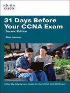
Header Format
To facilitate the routing of packets over a network, the TCP/IP protocol suite uses a 32-bit logical address known as an IP address. This address must be unique for each device in the internetwork.
Figure 21-1 shows the layout of the IPv4 header.
Note that each IP packet carries this header, which includes a source IP address and destination IP address.
An IP address consists of two parts:
![]() The high order, or left-most, bits specify the network address component (network ID) of the address.
The high order, or left-most, bits specify the network address component (network ID) of the address.
![]() The low order, or right-most, bits specify the host address component (host ID) of the address.
The low order, or right-most, bits specify the host address component (host ID) of the address.
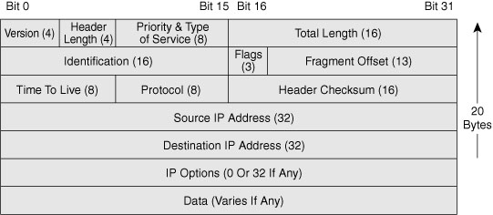
Classes of Addresses
From the beginning, IPv4 was designed with class structure: Class A, B, C, D and E. Class D is used for multicasting addresses and Class E is reserved for experimentation. Classes A, B, and C are assigned to network hosts. To provide a hierarchical structure, these classes are divided into network and host portions, as shown in Figure 21-2. The high-order bits specify the network ID, and the low order bits specify the host ID.
Note Today your ISP assigns you a block of addresses that has no relationship to the original classes. Based on your needs, you could be assigned one or more addresses. But with the use of NAT and private addresses inside your network, rarely will you need more than a handful of public IP addresses.
In a classful addressing scheme, devices that operate at Layer 3 can determine the address class of an IP address from the format of the first few bits in the first octet. Initially, this was important so that a networking device could apply the default subnet mask for the address and determine the host address. Table 21-1 summarizes how addresses are divided into classes, the default subnet mask, the number of networks per class, and the number of hosts per classful network address.

In the last column, the “minus 2” for hosts per network is to account for the reserved network and broadcast addresses for each network. These two addresses cannot be assigned to hosts.
Note We are not reviewing the process of converting between binary and decimal. At this point in your studies, you should be very comfortable moving between the two numbering systems. If not, take some time to practice this necessary skill. Refer to the “Study Resources” section. You can also search the Internet for binary conversion tricks, tips, and games to help you practice.
Purpose of the Subnet Mask
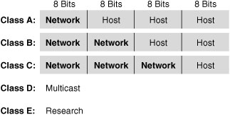
Subnet masks are always a series of one bits followed by a series of zero bits. The boundary where the series changes from ones to zeros is the boundary between network and host. This is how a device that operates at Layer 3 determines the network address for a packet—by finding the bit boundary where the series of one bits ends and the series of zero bits begins. The bit boundary for subnet masks break on the octet boundary. Determining the network address for an IP address that uses a default mask is easy.
For example, a router receives a packet destined for 192.168.1.51. By “ANDing” the IP address and the subnet mask, the router determines the network address for the packet. By the “ANDing” rules, a one AND a one equals one. All other possibilities equal zero. Table 21-2 shows the results of the “ANDing” operation. Notice that the host bits in the last octet are ignored.
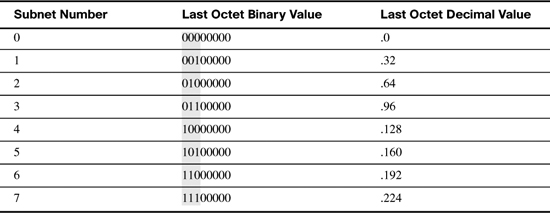
With the advent of CIDR using VLSM, the bit boundary can now occur in just about any place in the 32 bits. Table 21-3 summarizes the values for the last nonzero octet in a subnet mask.

Subnetting in Four Steps
Everyone has a preferred method of subnetting. Each teacher will use a slightly different strategy to help students master this crucial skill. Each of the suggested “Study Resources” has a slightly different way of approaching this subject.
The method I prefer can be broken down into four steps:
Step 1 Determine how many bits to borrow based on the network requirements.
Step 2 Determine the new subnet mask.
Step 3 Determine the subnet multiplier.
Step 4 List the subnets including subnetwork address, host range, and broadcast address.
The best way to demonstrate this method is to use an example. Let’s assume you are given the network address 192.168.1.0 with the default subnet mask 255.255.255.0. The network address and subnet mask can be written as 192.168.1.0/24. The “slash 24” represents the subnet mask in a shorter notation and means the first 24 bits are network bits.
Let’s further assume you need 30 hosts per network and want to create as many subnets for the given address space as possible. With these network requirements, let’s subnet the address space.
Determine How Many Bits to Borrow
To determine the number of bits you can borrow, you first must know how many host bits you have to start with. Because the first 24 bits are network bits in our example, the remaining 8 bits are host bits.
Because our requirement specifies 30 host addresses per subnet, we need to first determine the minimum number of host bits to leave. The remaining bits can be borrowed:
Host Bits = Bits Borrowed + Bits Left
To provide enough address space for 30 hosts, we need to leave 5 bits. Use the following formula:
2BL – 2 = number of host addresses
where the exponent BL is bits left in the host portion.
Remember, the “minus 2” is to account for the network and broadcast addresses that cannot be assigned to hosts.
In this example, leaving 5 bits in the host portion will provide the right amount of host address: 25 – 2 = 30.
Because we have 3 bits remaining in the original host portion, we borrow all these bits to satisfy the requirement to “create as many subnets as possible.” To determine how many subnets we can create, use the following formula:
2BB = number of subnets
where the exponent BB is bits borrowed from the host portion.
In this example, borrowing 3 bits from the host portion will create 8 subnets: 23 = 8.
As shown in Table 21-4, the 3 bits are borrowed from the left-most bits in the host portion. The highlighted bits in the table show all possible combinations of manipulating the 8 bits borrowed to create the subnets.
Determine the New Subnet Mask
Notice in Table 21-4 that the network bits now include the 3 borrowed host bits in the last octet. Add these 3 bits to the 24 bits in the original subnet mask and you have a new subnet mask, /27. In decimal format, you turn on the 128, 64, and 32 bits in the last octet for a value of 224. So the new subnet mask is 255.255.255.224.
Determine the Subnet Multiplier
Notice in Table 21-4 that the last octet decimal value increments by 32 with each subnet number. The number 32 is the subnet multiplier. You can quickly find the subnet multiplier using one of two methods:
![]() Method 1:Subtract the last nonzero octet of the subnet mask from 256. In this example, the last nonzero octet is 224. So the subnet multiplier is 256 – 224 = 32.
Method 1:Subtract the last nonzero octet of the subnet mask from 256. In this example, the last nonzero octet is 224. So the subnet multiplier is 256 – 224 = 32.
![]() Method 2:The decimal value of the last bit borrowed is the subnet multiplier. In this example, we borrowed the 128 bit, the 64 bit, and the 32 bit. The 32 bit is the last bit we borrowed and is, therefore, the subnet multiplier.
Method 2:The decimal value of the last bit borrowed is the subnet multiplier. In this example, we borrowed the 128 bit, the 64 bit, and the 32 bit. The 32 bit is the last bit we borrowed and is, therefore, the subnet multiplier.
By using the subnet multiplier, you no longer have to convert binary subnet bits to decimal.
List the Subnets, Host Ranges, and Broadcast Addresses
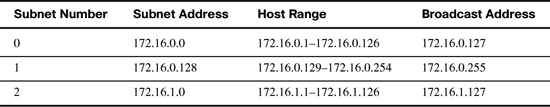
Listing the subnets, host ranges, and broadcast addresses helps you see the flow of addresses within one address space. Table 21-5 documents our subnet addressing scheme for the 192.168.1.0/24 address space.

The following are three examples using the four subnetting steps. For brevity, only the first three subnets are listed in step 4.
Subnetting Example 1
Subnet the address space 172.16.0.0/16 to provide at least 80 host addresses per subnet while creating as many subnets as possible.
-
There are 16 host bits. Leave 7 bits for host addresses (27 – 2 = 126 host addresses per subnet). Borrow the first 9 host bits to create as many subnets as possible (29 = 512 subnets).
-
The original subnet mask is /16 or 255.255.0.0. Turn on the next 9 bits starting in the second octet for a new subnet mask of /25 or 255.255.255.128.
-
The subnet multiplier is 128, which can be found as 256 – 128 = 128 or because the 128 bit is the last bit borrowed.
-
Table 21-6 lists the first three subnets, host ranges, and broadcast addresses.
Subnetting Example 2
Subnet the address space 172.16.0.0/16 to provide at least 80 subnet addresses.
-
There are 16 host bits. Borrow the first 7 host bits to create at least 80 subnets (27 = 126 subnets). That leaves 9 bits for host addresses or 29 – 2 = 510 host addresses per subnet.
-
The original subnet mask is /16 or 255.255.0.0. Turn on the next 7 bits starting in the second octet for a new subnet mask of /23 or 255.255.254.0.
-
The subnet multiplier is 2, which can be found as 256 – 254 = 2 or because the 2 bit is the last bit borrowed.
-
Table 21-7 lists the first three subnets, host ranges, and broadcast addresses.

Subnetting Example 3
Subnet the address space 172.16.10.0/23 to provide at least 60 host addresses per subnet while creating as many subnets as possible.
-
There are 9 host bits. Leave 6 bits for host addresses (26 – 2 = 62 host addresses per subnet). Borrow the first 3 host bits to create as many subnets as possible (23 = 8 subnets).
-
The original subnet mask is /23 or 255.255.254.0. Turn on the next 3 bits starting with the last bit in the second octet for a new subnet mask of /26 or 255.255.255.192.
-
The subnet multiplier is 64, which can be found as 256 – 192 = 64 or because the 64 bit is the last bit borrowed.
-
Table 21-7 lists the first three subnets, host ranges, and broadcast addresses.

VLSM
You probably noticed that the starting address space in Subnetting Example 3 is not an entire classful address. In fact, it is subnet 5 from Subnetting Example 2. So in Subnetting Example 3, we “subnetted a subnet.” That is what VLSM is in a nutshell—subnetting a subnet.
With VLSM, you can customize your subnets to fit your network. Subnetting works the same way. You just have to do it more than once to complete your addressing scheme. To avoid overlapping address spaces, start with your largest host requirement, create a subnet for it, and then continue with the next largest host requirement.
Let’s use a small example. Given the address space 172.30.4.0/22 and the network requirements shown in Figure 21-3, apply an addressing scheme that conserves the most amount of addresses for future growth.

We need five subnets: four LAN subnets and one WAN subnet. Starting with the largest host requirement on LAN 3, begin subnetting the address space.
To satisfy the 250 hosts requirement, we leave 8 hosts bits (28 – 2 = 254 hosts per subnet). Because we have 10 host bits total, we borrow 2 bits to create the first round of subnets (22 = 4 subnets). The starting subnet mask is /22 or 255.255.252.0. We turn on the next two bits in the subnet mask to get /24 or 255.255.255.0. The multiplier is 1. The four subnets are as follows:
![]() Subnet 1:172.30.5.0/24
Subnet 1:172.30.5.0/24
![]() Subnet 2:172.30.6.0/24
Subnet 2:172.30.6.0/24
![]() Subnet 3:172.30.7.0/24
Subnet 3:172.30.7.0/24
Assigning Subnet 0 to LAN 3, we are left with three /24 subnets. Continuing on to the next largest host requirement on LAN 4, we take Subnet 1, 172.30.5.0/24, and subnet it further.
To satisfy the 100 hosts requirement, we leave 7 bits (27 – 2 = 128 hosts per subnet). Because we have 8 host bits total, we can borrow only 1 bit to create the subnets (21 = 2 subnets). The starting subnet mask is /24 or 255.255.255.0. We turn on the next bit in the subnet mask to get /25 or 255.255.255.128. The multiplier is 128. The two subnets are as follows:
![]() Subnet 0:172.30.5.0/25
Subnet 0:172.30.5.0/25
![]() Subnet 1:172.30.5.128/25
Subnet 1:172.30.5.128/25
Assigning Subnet 0 to LAN 4, we are left with one /25 subnet and two /24 subnets. Continuing on to the next largest host requirement on LAN 1, we take Subnet 1, 172.30.5.128/24, and subnet it further.
To satisfy the 60 hosts requirement, we leave 6 bits (26 – 2 = 62 hosts per subnet). Because we have 7 host bits total, we borrow 1 bit to create the subnets (21 = 2 subnets). The starting subnet mask is /25 or 255.255.255.128. We turn on the next bit in the subnet mask to get /26 or 255.255.255.192. The multiplier is 64. The two subnets are as follows:
![]() Subnet 0:172.30.5.128/26
Subnet 0:172.30.5.128/26
![]() Subnet 1:172.30.5.192/26
Subnet 1:172.30.5.192/26
Assigning Subnet 0 to LAN 1, we are left with one /26 subnet and two /24 subnets. Finishing our LAN subnetting with LAN 2, we take Subnet 1, 172.30.5.192/26, and subnet it further.
To satisfy the 10 hosts requirement, we leave 4 bits (24 – 2 = 14 hosts per subnet). Because we have 6 host bits total, we borrow 2 bits to create the subnets (22 = 4 subnets). The starting subnet mask is /26 or 255.255.255.192. We turn on the next two bits in the subnet mask to get /28 or 255.255.255.240. The multiplier is 16. The four subnets are as follows:
![]() Subnet 0:172.30.5.192/28
Subnet 0:172.30.5.192/28
![]() Subnet 1:172.30.5.208/28
Subnet 1:172.30.5.208/28
![]() Subnet 2:172.30.5.224/28
Subnet 2:172.30.5.224/28
![]() Subnet 3:172.30.5.240/28
Subnet 3:172.30.5.240/28
Assigning Subnet 0 to LAN 2, we are left with three /28 subnets and two /24 subnets. To finalize our addressing scheme, we need to create a subnet only for the WAN link, which needs only 2 host addresses. We take Subnet 1, 172.30.5.208/28, and subnet it further.
To satisfy the 2 host requirement, we leave 2 bits (22 – 2 = 2 hosts per subnet). Because we have 4 host bits total, we borrow 2 bits to create the subnets (22 = 4 subnets). The starting subnet mask is /28 or 255.255.255.240. We turn on the next two bits in the subnet mask to get /30 or 255.255.255.252. The multiplier is 4. The four subnets are as follows:
![]() Subnet 1:172.30.5.212/30
Subnet 1:172.30.5.212/30
![]() Subnet 2:172.30.5.216/30
Subnet 2:172.30.5.216/30
![]() Subnet 3:172.30.5.220/30
Subnet 3:172.30.5.220/30
We assign Subnet 0 to the WAN link. We are left with three /30 subnets, two /28 subnets, and two /24 subnets.
Summarizing Subnet Addresses
When a network’s addressing scheme is designed hierarchically, summarizing addresses to upstream routers makes routing much more efficient. Instead of sending a collection of various subnets, a border router can send one summary route to the next router.
If you are using static routing or configuring a summary route for EIGRP, you might need to calculate the right network prefix and subnet mask.
Referring to Figure 21-4, what summary route would R1 send to the upstream router, BBR (Backbone Router) for the four subnets?

Use the following steps to calculate a summary route:
Step 1 Write out the networks that you want to summarize in binary, as shown following Step 4.
Step 2 To find the subnet mask for summarization, start with the left-most bit.
Step 3 Work your way to the right, finding all the bits that match consecutively.
Step 4 When you find a column of bits that do not match, stop. You are at the summary boundary.
11000000.10101000.00000001.00000000
11000000.10101000.00000001.00100000
11000000.10101000.00000001.01000000
11000000.10101000.00000001.01100000
Step 5 Count the number of left-most matching bits, which in this example is 25. This number becomes your subnet mask for the summarized route, /25 or 255.255.255.128.
Step 6 To find the network address for summarization, copy the matching 25 bits and add all 0 bits to the end to make 32 bits. In this example, the network address is 192.168.1.0.
In production networks, the subnets to be summarized most likely will not have the same subnet mask. For example, the subnets in Figure 21-5 are using three different subnet masks. What summary route would R1 send to BBR for the four subnets?

Use the same steps to calculate the summary.
10101100.00010000.00000000.00000000
10101100.00010000.10000000.00000000
10101100.00010001.00000000.00000000
10101100.00010010.00000000.00000000
Summary Route: 172.16.0.0/14
Private and Public IP Addressing
RFC 1918, “Address Allocation for Private Internets,” eased the demand for IP addresses by reserving the following addresses for use in private internetworks.
![]() Class A:10.0.0.0/8 (10.0.0.0 to 10.255.255.255)
Class A:10.0.0.0/8 (10.0.0.0 to 10.255.255.255)
![]() Class B:172.16.0.0/12 (172.16.0.0 to 172.31.255.255)
Class B:172.16.0.0/12 (172.16.0.0 to 172.31.255.255)
![]() Class C:192.168.0.0/16 (192.168.0.0 to 192.168.255.255)
Class C:192.168.0.0/16 (192.168.0.0 to 192.168.255.255)
If you are addressing a nonpublic intranet, these private addresses can be used instead of globally unique public addresses. This provides flexibility in your addressing design. Any organization can take full advantage of an entire Class A address (10.0.0.0/8). Forwarding traffic to the public Internet requires translation to a public address using network address translation (NAT). But by overloading an Internet routable address with many private addresses, a company needs only a handful of public addresses. Day 5, “NAT Concepts, Configuration, and Troubleshooting,” reviews NAT operation and configuration in greater detail.