Day 4 WAN and VPN Technologies
CCNA 640-802 Exam Topics
![]() Describe different methods for connecting to a WAN.
Describe different methods for connecting to a WAN.
![]() Describe VPN technology (importance, benefits, role, impact, components).
Describe VPN technology (importance, benefits, role, impact, components).
Key Topics
Today is a whirlwind review of WAN technologies, WAN connection options, and VPN. Because these exam topics are conceptual in nature, requiring no configuration skills, read this review several times. If necessary, refer to your study resources for more in-depth review.
WAN Technology Concepts
WAN access standards typically describe both physical layer delivery methods and data link layer requirements, including physical addressing, flow control, and encapsulation. The physical layer protocols describe how to provide electrical, mechanical, operational, and functional connections to a service provider. The data link layer protocols define how data is encapsulated and the mechanisms for transferring the resulting frames. A variety of technologies are used, such as Frame Relay and Asynchronous Transfer Mode (ATM). Some of these protocols use the same basic framing mechanism as High-Level Data Link Control (HDLC), an ISO standard, or one of its subsets or variants.
WAN Components and Devices
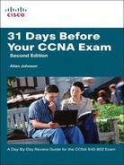
Figure 4-1 illustrates the terminology commonly used to describe physical WAN connections.
The WAN components shown in Figure 4-1 are described in further detail in the following list:
![]() Customer Premises Equipment (CPE):The devices located at the premises of the WAN subscriber. The subscriber either owns or leases the CPE.
Customer Premises Equipment (CPE):The devices located at the premises of the WAN subscriber. The subscriber either owns or leases the CPE.
![]() Data Communications Equipment (DCE):Consists of devices that put data on the local loop. The DCE primarily provides an interface to connect subscribers to the WAN cloud.
Data Communications Equipment (DCE):Consists of devices that put data on the local loop. The DCE primarily provides an interface to connect subscribers to the WAN cloud.
![]() Data Terminal Equipment (DTE):The customer devices that pass the data from a customer network to the DCE for transmission over the WAN.
Data Terminal Equipment (DTE):The customer devices that pass the data from a customer network to the DCE for transmission over the WAN.
![]() Local loop:The copper or fiber cable that connects the CPE the central office (CO) of the service provider. The local loop is sometimes called the “last mile.”
Local loop:The copper or fiber cable that connects the CPE the central office (CO) of the service provider. The local loop is sometimes called the “last mile.”
![]() Demarcation point:A point where customer equipment is separated from service provider equipment. It is the place where the responsibility for the connection changes from the customer to the service provider.
Demarcation point:A point where customer equipment is separated from service provider equipment. It is the place where the responsibility for the connection changes from the customer to the service provider.
![]() Central office (CO):A local service provider facility or building where local cables link to long-haul, all-digital, fiber-optic communications lines through a system of switches and other equipment.
Central office (CO):A local service provider facility or building where local cables link to long-haul, all-digital, fiber-optic communications lines through a system of switches and other equipment.
WANs use numerous types of devices that are specific to WAN environments:
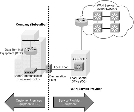
![]() Modem:Modulates and demodulates between analog and digital signals.
Modem:Modulates and demodulates between analog and digital signals.
![]() CSU/DSU:A channel service unit (CSU) and a data service unit (DSU) often combined into a single piece of equipment to provide the termination for the digital signal and ensure connection integrity through error correction and line monitoring. It interprets frames from the carrier into frames that LAN devices can interpret and vice versa.
CSU/DSU:A channel service unit (CSU) and a data service unit (DSU) often combined into a single piece of equipment to provide the termination for the digital signal and ensure connection integrity through error correction and line monitoring. It interprets frames from the carrier into frames that LAN devices can interpret and vice versa.
![]() Access server:Concentrates dial-in and dial-out user communications. An access server might have a mixture of analog and digital interfaces and support hundreds of simultaneous users.
Access server:Concentrates dial-in and dial-out user communications. An access server might have a mixture of analog and digital interfaces and support hundreds of simultaneous users.
![]() WAN switch:A multiport internetworking device used in carrier networks. These devices typically switch traffic such as Frame Relay, ATM, or X.25 and operate at the data link layer of the OSI reference model. Public switched telephone network (PSTN) switches might also be used within the cloud for circuit-switched connections such as (ISDN) or analog dialup.
WAN switch:A multiport internetworking device used in carrier networks. These devices typically switch traffic such as Frame Relay, ATM, or X.25 and operate at the data link layer of the OSI reference model. Public switched telephone network (PSTN) switches might also be used within the cloud for circuit-switched connections such as (ISDN) or analog dialup.
![]() Router:Provides internetworking and WAN access interface ports that are used to connect to the service provider network.
Router:Provides internetworking and WAN access interface ports that are used to connect to the service provider network.
![]() Core router:A service provider router that resides within the middle or backbone of the WAN rather than at its periphery. To fulfill this role, a router must be able to support multiple telecommunications interfaces of the highest speed in use in the WAN core, and it must be able to forward IP packets at full speed on all those interfaces. The router must also support the routing protocols being used in the core.
Core router:A service provider router that resides within the middle or backbone of the WAN rather than at its periphery. To fulfill this role, a router must be able to support multiple telecommunications interfaces of the highest speed in use in the WAN core, and it must be able to forward IP packets at full speed on all those interfaces. The router must also support the routing protocols being used in the core.
Figure 4-2 shows the name and typical location of various WAN devices.
WAN Physical Layer Standards
The WAN physical layer also describes the interface between the DTE and DCE. A Cisco router’s serial interface is capable of connecting to a CSU/DSU that uses any of the following standards:
![]() EIA/TIA-232:This protocol allows signal speeds of up to 64 kbps on a 25-pin D-connector over short distances. It was formerly known as RS-232. The ITU-T V.24 specification is effectively the same.
EIA/TIA-232:This protocol allows signal speeds of up to 64 kbps on a 25-pin D-connector over short distances. It was formerly known as RS-232. The ITU-T V.24 specification is effectively the same.
![]() EIA/TIA-449/530:This protocol is a faster (up to 2 Mbps) version of EIA/TIA-232. It uses a 36-pin D-connector and is capable of longer cable runs. Several versions exist. This standard is also known as RS-422 and RS-423.
EIA/TIA-449/530:This protocol is a faster (up to 2 Mbps) version of EIA/TIA-232. It uses a 36-pin D-connector and is capable of longer cable runs. Several versions exist. This standard is also known as RS-422 and RS-423.
![]() V.35:This is the ITU-T standard for synchronous communications between a network access device and a packet network. Originally specified to support data rates of 48 kbps, it now supports speeds of up to 2.048 Mbps using a 34-pin rectangular connector.
V.35:This is the ITU-T standard for synchronous communications between a network access device and a packet network. Originally specified to support data rates of 48 kbps, it now supports speeds of up to 2.048 Mbps using a 34-pin rectangular connector.
![]() X.21:This protocol is an ITU-T standard for synchronous digital communications. It uses a 15-pin D-connector.
X.21:This protocol is an ITU-T standard for synchronous digital communications. It uses a 15-pin D-connector.
![]() EIA/TIA-612/613:(not shown in Figure 4-3) This standard describes the High-Speed Serial Interface (HSSI) protocol, which provides access to services up to 52 Mbps on a 60-pin D-connector.
EIA/TIA-612/613:(not shown in Figure 4-3) This standard describes the High-Speed Serial Interface (HSSI) protocol, which provides access to services up to 52 Mbps on a 60-pin D-connector.

Notice in Figure 4-3 that the router connection at the top is the same regardless of the connection used by CSU/DSU. The network administrator simply chooses the correct cable for the CSU/DSU connection.
WAN Data Link Protocols
Each WAN connection type uses a Layer 2 protocol to encapsulate a packet while it is crossing the WAN link. To ensure that the correct encapsulation protocol is used, the Layer 2 encapsulation type used for each router serial interface must be configured, if different than the default. The choice of encapsulation protocols depends on the WAN technology and the equipment. The most common WAN data link protocols are as follows:
![]() HDLC (Cisco default)
HDLC (Cisco default)
![]() Point-to-Point Protocol (PPP)
Point-to-Point Protocol (PPP)
![]() Frame Relay
Frame Relay
![]() Asynchronous Transfer Mode (ATM)
Asynchronous Transfer Mode (ATM)
WAN Switching
WAN switched networks are categorized as either circuit-switched or packet-switched. A circuit-switched network is one that establishes a dedicated circuit (or channel) between nodes and terminals before the users can communicate. Although the circuit is dedicated for the duration of the call, the physical link is share by multiple end users through a process called time-division multiplexing (TDM). TDM gives each conversation a share of the connection in turn and ensures that a fixed-capacity connection is made available to the subscriber. PSTN and ISDN are two types of circuit-switching technology that can be used to implement a WAN in an enterprise setting.
In contrast to circuit switching, packet switching splits traffic data into packets that are routed over a shared network. Packet-switching networks do not require a circuit to be established, and they allow many pairs of end users to communicate over the same channel. The switches in a packet-switched network use one of the following methods to determine which link the packet must be sent on next from the addressing information in each packet:
![]() Connectionless systems, such as the Internet, carry full addressing information in each packet. Each packet switch or router must evaluate the destination IP address to determine where to send the packet.
Connectionless systems, such as the Internet, carry full addressing information in each packet. Each packet switch or router must evaluate the destination IP address to determine where to send the packet.
![]() Connection-oriented systems predetermine a packet’s route, and each packet only has to carry an identifier, such as Data Link Connection Identifiers (DLCIs) in Frame Relay.
Connection-oriented systems predetermine a packet’s route, and each packet only has to carry an identifier, such as Data Link Connection Identifiers (DLCIs) in Frame Relay.
Packet-switched networks can establish routes through the switches for particular end-to-end connections. These routes are called virtual circuits (VCs). A VC is a logical circuit between two network devices to help ensure reliable communications. Two types of VCs exist:
![]() Permanent virtual circuit (PVC):A permanently established virtual circuit that consists of one mode—data transfer. PVCs are used in situations in which data transfer between devices is constant.
Permanent virtual circuit (PVC):A permanently established virtual circuit that consists of one mode—data transfer. PVCs are used in situations in which data transfer between devices is constant.
![]() Switched virtual circuit (SVC):A VC that is dynamically established on demand and terminated when transmission is complete. Communication over an SVC consists of three phases: circuit establishment, data transfer, and circuit termination. SVCs are used in situations in which data transmission between devices is intermittent, largely to save costs.
Switched virtual circuit (SVC):A VC that is dynamically established on demand and terminated when transmission is complete. Communication over an SVC consists of three phases: circuit establishment, data transfer, and circuit termination. SVCs are used in situations in which data transmission between devices is intermittent, largely to save costs.
WAN Connection Options
Many options for implementing WAN solutions are currently available. They differ in technology, speed, and cost. Figure 4-4 provides a high-level view of the various WAN link connection options, and the sections that follow describe these options in more detail.

Dedicated Connection Options
Also called leased lines, dedicated connections are preestablished point-to-point WAN connections from the customer premises through the provider network to a remote destination, as shown in Figure 4-5.

Leased lines are usually more expensive than switched services because of the dedicated, “always on” cost of providing WAN service to the customer. The dedicated capacity removes latency and jitter and provides a layer of security because only the customer’s traffic is allowed on the link. Table 4-1 lists the available leased-line types and their bit-rate capacities.

Circuit-Switched Connection Options
The two main types of circuit-switched connections are analog dialup and ISDN.
Analog Dialup
Analog dialup using modems and telephone lines is an ideal WAN connection solution when intermittent, low-volume data transfers are needed. Figure 4-6 shows a typical analog dialup connection.

These relatively low-speed dialup connections are adequate for the exchange of sales figures, prices, routine reports, and email. Using automatic dialup at night or on weekends for large file transfers and data backup can take advantage of lower off-peak tariffs (line charges). The advantages of modem and analog lines are simplicity, availability, and low implementation cost. The disadvantages are the low data rates and a relatively long connection time.
ISDN
ISDN turns the local loop into a TDM digital connection, which enables it to carry digital signals that result in higher-capacity switched connections. The connection uses 64-kbps bearer (B) channels to carry voice or data and a signaling, delta (D) channel for call setup and other purposes. There are two types of ISDN interfaces:
![]() Basic Rate Interface (BRI):Provides two 64-kbps B channels for voice or data transfer and a 16-kbps D channel used for control signaling.
Basic Rate Interface (BRI):Provides two 64-kbps B channels for voice or data transfer and a 16-kbps D channel used for control signaling.
![]() Primary Rate Interface (PRI):Provides 23 B channels with 64 kbps and one D channel with 64 kbps in North America, for a total bit rate of up to 1.544 Mbps. Europe uses 30 B channels and one D channel, for a total bit rate of up to 2.048 Mbps.
Primary Rate Interface (PRI):Provides 23 B channels with 64 kbps and one D channel with 64 kbps in North America, for a total bit rate of up to 1.544 Mbps. Europe uses 30 B channels and one D channel, for a total bit rate of up to 2.048 Mbps.
Figure 4-7 illustrates the various differences between ISDN BRI and PRI lines.

Packet-Switched Connection Options
The most common packet-switching technologies used in today’s enterprise WANs include legacy X.25, Frame Relay, and ATM.
X.25
X.25 is a legacy network-layer protocol. SVCs are established through the network for intermittent use of applications such as point-of-sale card readers. X.25 networks vary from 2400 bps up to 2 Mbps and are now in dramatic decline, being replaced by newer technologies such as Frame Relay, ATM, and DSL.
Frame Relay
Figure 4-8 shows a simplified Frame Relay network.

Frame Relay differs from X.25 in several ways. Most importantly, it is a much simpler protocol, operating strictly at Layer 2, whereas X.25 additionally provides Layer 3 services. Unlike X.25, Frame Relay implements no error or flow control. The simplified handling of frames leads to reduced latency, and measures taken to avoid frame buildup at intermediate switches help reduce jitter. Frame Relay offers data rates up to 4 Mbps, with some providers offering even higher rates. Frame Relay VCs are uniquely identified by a DLCI, which ensures bidirectional communication from one DTE device to another. Most Frame Relay connections are PVCs rather than SVCs.
ATM
Figure 4-9 shows an ATM network.
ATM is built on a cell-based architecture rather than on a frame-based architecture. ATM cells are always a fixed length of 53 bytes. The ATM cell contains a 5-byte ATM header followed by 48 bytes of ATM payload. Small, fixed-length cells are well suited for carrying voice and video traffic, because this traffic is intolerant of delay. Video and voice traffic do not have to wait for a larger data packet to be transmitted. Although ATM is less efficient than Frame Relay because of its 5 byte per cell overhead, it offers link speeds of T1/E1 to OC-12 (622 Mbps) and higher.
Internet Connection Options
Broadband connection options typically are used to connect telecommuting employees to a corporate site over the Internet. These options include DSL, cable, wireless, and Metro Ethernet.
DSL
DSL technology, shown in Figure 4-10, is an always-on connection technology that uses existing twisted-pair telephone lines to transport high-bandwidth data and provides IP services to subscribers.

Current DSL technologies use sophisticated coding and modulation techniques to achieve data rates of up to 8.192 Mbps. A variety of DSL types, standards, and emerging technologies exist. DSL is now a popular choice for enterprise IT departments to support home workers. Generally, a subscriber cannot choose to connect to an enterprise network directly.
Cable Modem
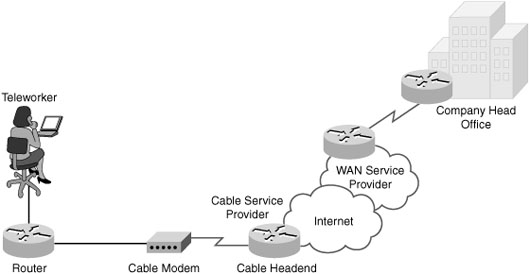
Cable modems provide an always-on connection and a simple installation. Figure 4-11 shows how a subscriber connects a computer or LAN router to the cable modem, which translates the digital signals into the broadband frequencies used for transmitting on a cable television network.
Broadband Wireless
Until recently, the main limitation of wireless access has been the need to be within range of a wireless router or a wireless modem that has a wired connection to the Internet. The following new developments in broadband wireless technology are changing this situation:
![]() Municipal Wi-Fi:Many cities have begun setting up municipal wireless networks. Some of these networks provide high-speed Internet access for free or for substantially less than the price of other broadband services.
Municipal Wi-Fi:Many cities have begun setting up municipal wireless networks. Some of these networks provide high-speed Internet access for free or for substantially less than the price of other broadband services.
![]() WiMAX:Worldwide Interoperability for Microwave Access (WiMAX) is a new IEEE 802.16 technology that is just beginning to come into use. It provides high-speed broadband service with wireless access and provides broad coverage like a cell phone network rather than through small Wi-Fi hotspots.
WiMAX:Worldwide Interoperability for Microwave Access (WiMAX) is a new IEEE 802.16 technology that is just beginning to come into use. It provides high-speed broadband service with wireless access and provides broad coverage like a cell phone network rather than through small Wi-Fi hotspots.
![]() Satellite Internet:Typically used by rural users where cable and DSL are unavailable.
Satellite Internet:Typically used by rural users where cable and DSL are unavailable.
Metro Ethernet
Metro Ethernet uses IP-aware Ethernet switches in the service provider’s network cloud to offer enterprises converged voice, data, and video services at Ethernet speeds. Some benefits of Metro Ethernet include the following:
![]() Reduced expenses and administration:Enables businesses to inexpensively connect numerous sites in a metropolitan area to each other and to the Internet without the need for expensive conversions to ATM or Frame Relay.
Reduced expenses and administration:Enables businesses to inexpensively connect numerous sites in a metropolitan area to each other and to the Internet without the need for expensive conversions to ATM or Frame Relay.
![]() Easy integration with existing networks:Connects easily to existing Ethernet LANs.
Easy integration with existing networks:Connects easily to existing Ethernet LANs.
![]() Enhanced business productivity:Metro Ethernet enables businesses to take advantage of productivity-enhancing IP applications that are difficult to implement on TDM or Frame Relay networks, such as hosted IP communications, VoIP, and streaming and broadcast video.
Enhanced business productivity:Metro Ethernet enables businesses to take advantage of productivity-enhancing IP applications that are difficult to implement on TDM or Frame Relay networks, such as hosted IP communications, VoIP, and streaming and broadcast video.
Choosing a WAN Link Option
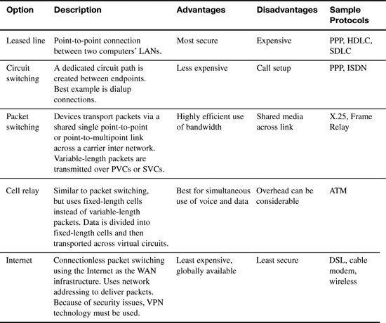
Table 4-2 compares the advantages and disadvantages of the various WAN connection options reviewed.
VPN Technology
A virtual private network (VPN) is an encrypted connection between private networks over a public network such as the Internet. Instead of using a dedicated Layer 2 connection such as a leased line, a VPN uses virtual connections called VPN tunnels, which are routed through the Internet from the company’s private network to the remote site or employee host.
VPN Benefits
Benefits of VPN include the following:
![]() Cost savings:Eliminates the need for expensive dedicated WAN links and modem banks.
Cost savings:Eliminates the need for expensive dedicated WAN links and modem banks.
![]() Security:Uses advanced encryption and authentication protocols that protect data from unauthorized access.
Security:Uses advanced encryption and authentication protocols that protect data from unauthorized access.
![]() Scalability:Can add large amounts of capacity without adding significant infrastructure.
Scalability:Can add large amounts of capacity without adding significant infrastructure.
![]() Compatibility with broadband technology:Supported by broadband service providers so mobile workers and telecommuters can take advantage of their home high-speed Internet service to access their corporate networks.
Compatibility with broadband technology:Supported by broadband service providers so mobile workers and telecommuters can take advantage of their home high-speed Internet service to access their corporate networks.
Types of VPN Access
Two types of VPN access exist:
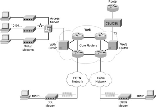
![]() Site-to-site VPNs:Connect entire networks to each other. For example, they can connect a branch office network to a company headquarters network, as shown in Figure 4-12. Each site is equipped with a VPN gateway, such as a router, firewall, VPN concentrator, or security appliance. In the figure, a remote branch office uses a site-to-site VPN to connect with the corporate head office.
Site-to-site VPNs:Connect entire networks to each other. For example, they can connect a branch office network to a company headquarters network, as shown in Figure 4-12. Each site is equipped with a VPN gateway, such as a router, firewall, VPN concentrator, or security appliance. In the figure, a remote branch office uses a site-to-site VPN to connect with the corporate head office.

![]() Remote-access VPNs:Remote-access VPNs enable individual hosts, such as telecommuters, mobile users, and extranet consumers, to access a company network securely over the Internet, as shown in Figure 4-13. Each host typically has VPN client software loaded or uses a web-based client.
Remote-access VPNs:Remote-access VPNs enable individual hosts, such as telecommuters, mobile users, and extranet consumers, to access a company network securely over the Internet, as shown in Figure 4-13. Each host typically has VPN client software loaded or uses a web-based client.

VPN Components
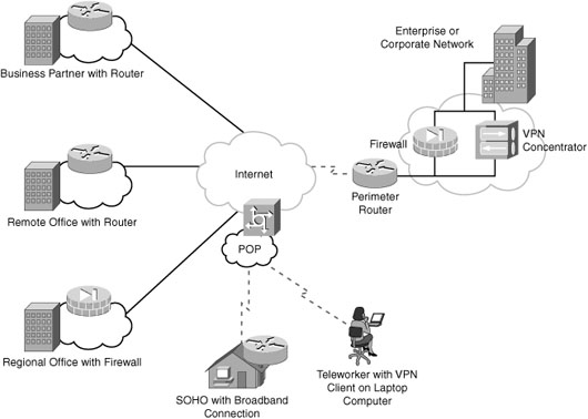
Figure 4-14 illustrates a typical VPN topology. Components required to establish this VPN include the following:
![]() An existing enterprise network with servers and workstations
An existing enterprise network with servers and workstations
![]() A connection to the Internet
A connection to the Internet
![]() VPN gateways, such as routers, firewalls, VPN concentrators, and ASAs, that act as endpoints to establish, manage, and control VPN connections
VPN gateways, such as routers, firewalls, VPN concentrators, and ASAs, that act as endpoints to establish, manage, and control VPN connections
![]() Appropriate software to create and manage VPN tunnels
Appropriate software to create and manage VPN tunnels
Establishing Secure VPN Connections
VPNs secure data by encapsulating and encrypting it. With regard to VPNs, encapsulation and encryption are defined as follows:
![]() Encapsulation is also called tunneling, because encapsulation transmits data transparently from source network to destination network through a shared network infrastructure.
Encapsulation is also called tunneling, because encapsulation transmits data transparently from source network to destination network through a shared network infrastructure.
![]() Encryption codes data into a different format using a secret key, which is then used on the other side on the connection to decrypt.
Encryption codes data into a different format using a secret key, which is then used on the other side on the connection to decrypt.
VPN Tunneling
Tunneling uses three classes of protocols:
![]() Carrier protocol:The protocol over which information travels (Frame Relay, ATM, MPLS).
Carrier protocol:The protocol over which information travels (Frame Relay, ATM, MPLS).
![]() Encapsulating protocol:The protocol that is wrapped around the original data (GRE, IPsec, L2F, PPTP, L2TP).
Encapsulating protocol:The protocol that is wrapped around the original data (GRE, IPsec, L2F, PPTP, L2TP).
![]() Passenger protocol:The protocol over which the original data was carried (IPX, AppleTalk, IPv4, IPv6).
Passenger protocol:The protocol over which the original data was carried (IPX, AppleTalk, IPv4, IPv6).
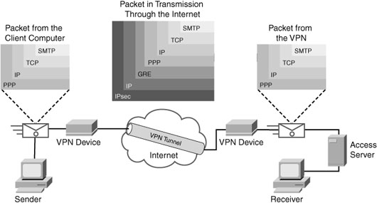
Figure 4-15 illustrates an email message traveling through the Internet over a VPN connection.
VPN Encryption Algorithms
The degree of security provided by any encryption algorithm depends on the key’s length. Some of the more common encryption algorithms and the length of the keys they use are as follows:
![]() Data Encryption Standard (DES) algorithm:Uses a 56-bit key, ensuring high-performance encryption. DES is a symmetric key cryptosystem.
Data Encryption Standard (DES) algorithm:Uses a 56-bit key, ensuring high-performance encryption. DES is a symmetric key cryptosystem.
![]() Triple DES (3DES) algorithm:A newer variant of DES that encrypts with one key, decrypts with a different key, and then encrypts a final time with another key.
Triple DES (3DES) algorithm:A newer variant of DES that encrypts with one key, decrypts with a different key, and then encrypts a final time with another key.
![]() Advanced Encryption Standard (AES):AES provides stronger security than DES and is computationally more efficient than 3DES. AES offers three key lengths: 128-, 192-, and 256-bit keys.
Advanced Encryption Standard (AES):AES provides stronger security than DES and is computationally more efficient than 3DES. AES offers three key lengths: 128-, 192-, and 256-bit keys.
![]() Rivest, Shamir, and Adleman (RSA):An asymmetric key cryptosystem. The keys use a bit length of 512, 768, 1024, or larger.
Rivest, Shamir, and Adleman (RSA):An asymmetric key cryptosystem. The keys use a bit length of 512, 768, 1024, or larger.
Symmetric encryption is when the encryption key and decryption key are the same. With asymmetric encryption, they are different.
Hashes
VPNs use a keyed hashed message authentication code (HMAC) data-integrity algorithm to guarantee a message’s integrity and authenticity without using any additional mechanisms.
The cryptographic strength of the HMAC depends on the cryptographic strength of the underlying hash function, on the key’s size and quality, and the size of the hash output length in bits. The two common HMAC algorithms are
![]() Message Digest 5 (MD5):Uses a 128-bit shared secret key.
Message Digest 5 (MD5):Uses a 128-bit shared secret key.
![]() Secure Hash Algorithm 1 (SHA-1):Uses a 160-bit secret key.
Secure Hash Algorithm 1 (SHA-1):Uses a 160-bit secret key.
Figure 4-16 shows an example using MD5 as the HMAC algorithm.

An HMAC has two parameters: a message input and a shared secret key known only to the message originator and intended receivers. In Figure 4-16, both R1 and R2 know the shared secret key. The process in Figure 4-16 uses the following steps:
-
R1 uses MD5 to perform the hashing function, which outputs a hash value. This hash value is then appended to the original message and sent to R2.
-
R2 the removes the hash value from the original message, runs the same hash operation, and then compares its hash value with the hash value sent by R1. If the two hashes match, the data integrity has not been compromised.
VPN Authentication
The device on the other end of the VPN tunnel must be authenticated before the communication path is considered secure. The two peer authentication methods are as follows:
![]() Preshared key (PSK):A secret key is shared between the two parties using a secure channel before it needs to be used.
Preshared key (PSK):A secret key is shared between the two parties using a secure channel before it needs to be used.
![]() RSA signature:Uses the exchange of digital certificates to authenticate the peers.
RSA signature:Uses the exchange of digital certificates to authenticate the peers.
IPsec Security Protocols
IPsec spells out the messaging necessary to secure VPN communications but relies on existing algorithms. The two main IPsec framework protocols are as follows:
![]() Authentication Header (AH):Used when confidentiality is not required or permitted. AH provides data authentication and integrity for IP packets passed between two systems. It verifies the originators of any messages and that any message passed has not been modified during transit. AH does not provide data confidentiality (encryption) of packets. Used alone, the AH protocol provides weak protection. Consequently, it is used with the ESP protocol to provide data encryption and tamper-aware security features.
Authentication Header (AH):Used when confidentiality is not required or permitted. AH provides data authentication and integrity for IP packets passed between two systems. It verifies the originators of any messages and that any message passed has not been modified during transit. AH does not provide data confidentiality (encryption) of packets. Used alone, the AH protocol provides weak protection. Consequently, it is used with the ESP protocol to provide data encryption and tamper-aware security features.
![]() Encapsulating Security Payload (ESP):Provides confidentiality and authentication by encrypting the IP packet. Although both encryption and authentication are optional in ESP, at a minimum, one of them must be selected.
Encapsulating Security Payload (ESP):Provides confidentiality and authentication by encrypting the IP packet. Although both encryption and authentication are optional in ESP, at a minimum, one of them must be selected.
IPsec relies on existing algorithms to implement encryption, authentication, and key exchange. Figure 4-17 shows how IPsec is structured.

IPsec provides the framework, and the administrator chooses the algorithms used to implement the security services within that framework. As Figure 4-17 illustrates, the administrator must fill the four IPsec framework squares:
![]() Choose an IPsec protocol.
Choose an IPsec protocol.
![]() Choose the encryption algorithm that is appropriate for the desired level of security.
Choose the encryption algorithm that is appropriate for the desired level of security.
![]() Choose an authentication algorithm to provide data integrity.
Choose an authentication algorithm to provide data integrity.
![]() The last square is the Diffie-Hellman (DH) algorithm group, which establishes the sharing of key information between peers. Choose which group to use—DH1, DH2, or DH5.
The last square is the Diffie-Hellman (DH) algorithm group, which establishes the sharing of key information between peers. Choose which group to use—DH1, DH2, or DH5.